Note : Les descriptions sont présentées dans la langue officielle dans laquelle elles ont été soumises.
CA 02278273 1999-07-21
BACKGROUND OF THE INVENTION
1. Field of the Invention
The invention relates to a device for the protection of objects or body parts
against
vibrations, in particular a vibration-damping glove or antivibration glove,
including at least
one vibration-damping layer.
2. Prior Art
Devices for the protection of the human body are known, for instance, as
protectors for
motorcyclists, which reduce the action of forces exerted on the body in the
event of an
accident involving crashing of the motorcyclist. DE 196 47 724 A1 describes
protectors for
1o protective motorcycle clothings, which are made of elastomers and include a
base provided
with elevations in the direction of the motorcyclist's body, which are aimed
at providing an
enhanced adaptability. Such protectors serve as protections against shocks or
impacts. In
order to reduce vibrations, gloves have been known, which, for instance,
according to US 5
632 045 A contain at least two layers of a damping material, one layer
consisting of a
viscoelastic material and one layer consisting of a foamed material. Another
glove
construction according to US 5 537 688 A includes a plurality of
interconnected liquid
containing blisters. Moreover, there are gloves for the protection against
heat and mechanical
influences, such as, for instance, the configuration according to WO 93/05670
A1, or gloves
exhibiting an enhanced grip and adherence. Such a glove, in particular a
goaltender's glove, is
2o described, for instance, in WO 95/34228 A1.
The field of the present invention relates to both the protection of objects
against
vibrations and the protection of at least parts of the human or animal body.
Whatever the
cause of vibrations may be, in most cases it is moved systems which bring
about undesired
vibrations as side effects. By appropriately constructing the moved systems,
it is sought to
keep such vibrations low or shift the frequencies of vibrations to ranges in
which they involve
fewer drawbacks. It is, however, not possible to exlude vibrations completely.
Therefore,
various attempts have been made to prevent the transmission of vibrations to
other objects or
on man, or admit only a reduced portion of the same.
In particular, the operation of vibrating tools such as, e.g., grinding
machines or the
like, frequently leads to temporary or chronical injuries of the persons
operating those
machines. Such injuries are known as hand arm vibration syndrome. The
consequences of
such injuries are high sickness figures, low outputs and claims for damages,
which constitute
high economic losses.
CA 02278273 1999-07-21
2
The field, however, is not limited to vibrating machines. The devices, for
instance,
may serve also for protecting against vibrations in vehicles or the like.
In terms of frequency, vibrations may be subdivided into those occurnng in the
medium frequency range of approximately 31.5 to 200 Hz and those occurring in
the high
frequency range of above 200 Hz. Currently available protective devices such
as, e.g.,
antivibration gloves are designed such that medium frequency range vibrations
will not be
increased and high frequency range vibrations will be lowered to a certain
percentage. There
have been known a number of antivibration gloves which cause the damping of
vibrations by
means of different materials in different material thicknesses. Thus, it is,
for instance, possible
l0 to insert shaped parts of polyurethane, elastomers, silicon gel or
polyolefine in a glove. In
order to achieve sufficient vibration damping, those shaped parts in most
cases are very thick,
thus extremely restricting maneuverability. This cannot be tolerated in the
application as a
glove. If, on the other hand, the shaped parts are made so thin as to involve
no substantial
restriction of the freedom of motion, vibration damping will be insufficient.
There are also
known cases in which the device for the protection against vibrations will
even increase the
latter in certain frequency ranges.
SUMMARY OF THE INVENTION
It is, therefore, the object of the present invention to provide a device for
the
protection against vibrations, by which noticeable damping of vibrations can
be achieved even
2o in the low-frequency range of vibrations. Moreover, the device for the
protection against
vibrations is to be configured so as to allow for as large a freedom of motion
as possible when
applied to the human body, yet also no mechanical blocking will occur when
applied directly
on machines or the like.
The object of the invention is achieved in that at least one vibration-damping
layer, on
its surface facing away from the object or body part to be protected,
comprises indents for
decoupling movements in at least one direction in the plane of the said
surface. The use of a
vibration-damping layer comprising the indents according to the invention
ensures that
vibrations will be sufficiently damped even in the low-frequency range, i.e.,
from
approximately 31.5 to 200 Hz while additionally providing as large a freedom
of motion as
possible. The surface of the vibration-damping layer, which is interrupted by
the indents, is in
direct or indirect contact with the source of vibration such that the
vibrations can be
effectively damped. When applying the device according to the invention as a
protection
against vibrations in the form of a vibration-damping glove, vibration-
dependent injuries can,
CA 02278273 1999-07-21
3
thus, be avoided and working can be continued over extented periods without
frequent breaks
and without the workers being jeopardized. Advantageously, the indents are
arranged as a
function of the geometry and the desired movability of the object or body part
to be protected.
According to another characteristic feature of the invention, the depth of an
indent
amounts to at least 60 %, preferably at least 80 % and, in a particularly
preferred manner, at
least 95 % of the thickness of the vibration-damping layer. Thereby, enhanced
decoupling of
the movements on the surface of the vibration-damping layer and hence enhanced
vibration
damping as well as an increased freedom of motion are achieved.
The width of the indents is at least so large that, at the maximum vibration-
damping
layer deformation possible, the layer formations located between the indents
are at least
partially decoupled from one another. Thereby, an optimum vibration-damping
effect is
obtained even at a deformation of the layer.
If the width of the indents increases in the direction of the surface of the
vibration-
damping layer, decoupling of the formations will be reached even at a
deformation of the
layer.
According to a further characteristic feature of the invention, at least one
vibration-
damping layer is comprised of a three-dimensional elastomer matrix, preferably
based on
polynorbonene, having vibration-damping plasticizers incorporated therein.
Unlike gelatinous
material groups, which exhibit a limited recovering behavior, an enhanced
dimensional
2o stability is achieved by means of a cross-linked elastomer matrix. By
applying such a cross-
linked structure, it is feasible to ensure optimum vibration damping even in
the lower
frequency ranges. This is achieved by the vibration-damping medium, in the
instant case the
vibration-damping plasticizer, being incorporated in the three-dimensional
cross-linked
elastomer matrix.
Good results are obtained if at least one vibration-damping layer has a
hardness of 18
Shore A at most, preferably 5 Shore A, and a rebound elasticity of 10 % at
most, preferably 3
%.
According to a further characteristic feature of the invention, the surface of
the
vibration-damping layer amounts to 20 % to 80 %, preferably 30 %, of the base
of the
vibration-damping layer. The smaller the surface of the vibration-damping
layer, the better the
movability of the protective device. Yet, on the other hand, the surface must
have a certain
minimum measure in order maintain its functionality and the transmission of a
retention force
via the protective device, in particular when used as a glove. This will be
assisted by the use
CA 02278273 1999-07-21
4
of a harder material when choosing a smaller surface of the vibration-damping
layer and a
softer material when choosing a larger surface. The use of a material having a
18 Shore A
hardness at an area portion of the surface facing the vibrating object of 20 %
of the base of the
vibration-damping layer, a material having a 5 Shore A hardness at a 30 % area
portion and,
finally, a material having a 3 Shore A hardness at a 80 % area portion have
proved to be
particularly suitable.
BRIEF DESCRIPTION OF THE DRAWINGS
The invention will be explained in more detail by way of the accompanying
drawings
wherein:
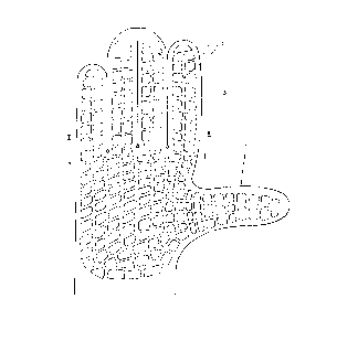
to Fig. 1 is a top view on an embodiment of a vibration-damping layer
according to the
invention for use in a vibration-damping glove;
Fig. 2 is a sectional illustration through the layer along the sectional line
II-II of Fig. 1;
Fig. 3 depicts the detail A of Fig. 2 on an enlarged scale; and
Fig. 4 shows part of a vibration-damping layer according to the invention in
order to
illustrate the desired movability.
DETAILED DESCRIPTION OF A PREFERRED EMBODIMENT OF THE INVENTION
Fig. 1 in the top view illustrates an embodiment of a vibration-damping layer
1
according to the invention to be applied in a vibration-damping glove. The
vibration-damping
layer 1 is substantially shaped like a human hand and, according to the
invention, comprises
indents 2 on its surface, which are arranged as a function of the desired
movement or
geometry of the object to be protected, i.e., the human hand in the instant
case. The
arrangement of a plurality of indents 2 results in a plurality of intermediate
formations 3. The
vibration-damping layer 1 is configured such that the surface 4 of the
formations 3 is located
substantially parallel with the base 5 of the layer 1. The resulting surface 4
of the formations 3
in that case is to be as large as possible in order to provide for as large as
possible an area of
contact with the vibrating object. The sectional illustration according to
Fig. 2 exemplifies a
cross sectional shape of the indents 2. The configuration of the vibration-
damping layer 1
according to the invention renders feasible that the vibrations oriented in
the direction of the
interior of the layer 1 are absorbed by the appropriate material and, in
addition, any
3o propagation of vibrations oriented in the direction of the plane of the
surface 4 of the layer 1
is effectively prevented. Movements on the surface 4 on the indents 2 are
partially forced into
the interior of the vibration-damping layer 1, where, for instance, the
conversion of vibration
energy into heat takes place. Investigations have demonstrated that, due to
the device
CA 02278273 1999-07-21
according to the invention, vibrations both in the medium and in the high
frequency ranges
are markedly reduced and that the freedom of motion is preserved,
nevertheless, in particular
when used in a glove.
In Fig. 3, which depicts the detail A of Fig. 2 on an enlarged scale,
preferred
dimensional ratios are elucidated. The depth T of the indents 2 occupies a
major portion of the
thickness D of the vibration-damping layer 1. Advantageously, the depth T is
at least 60 %,
preferably at least 80 % and, in a particularly preferred manner at least 95
%, of the thickness
D of the layer 1. The width B of the indents is as small as possible so as to
provide as large a
surface 4 as possible via which the vibrations can be taken up, yet, at the
same time, also at
to least so large as to prevent the transmission of movements in the direction
of the plane of the
surface 4 from one formation 3 to the adjacent formation 3. In the event the
vibration-
damping layer 1 may be exposed to a movement, as will, of course, be the case
with a
vibration-damping glove, the indents 2, in order to ensure sufficient
decoupling of such
movements in the direction of the plane of the surface 4 of the layer l, must
be selected to be
at least of such a width that contacting of the formations 3 will be prevented
even at the
maximum deformation of the layer 1 possible. Sporadical contacting is, of
course, tolerable,
yet the major portion of the formations 3 should be mutually decoupled so as
to ensure
optimum vibration damping. In order to provide for the optimum movability of
the layer l,
the indents 2 preferably are such that their width B increases in the
direction of the surface 4
of the layer 1. This may be achieved, for instance, by a trapezoidal shape
with the indents 2 on
the surface 4 having a width B i larger than the width B2 in the depth of the
indents 2. Instead
of a trapezoidal course, a curved or any other cross sectional course of the
indents 2 may be
chosen.
Fig. 4 refers to a borderline case, showing the maximum deformation of the
layer 1.
When applied in a glove, such a maximum deformation is, for instance, a
function of the
maximum curvature possible of the fingers. The shape of the indents 2 in that
case preferably
is selected so as to ensure a certain minimum width B",;~ of the indents 2
even upon such a
maximum deformation so that mutual decoupling of the formations 3 will occur
also in that
state of the layer 1.
3o It goes without saying that various modifications may be realized within
the scope of
the invention. Thus, it is, for instance, possible to superimpose several
layers l, wherein
different materials or material combinations may be employed. The indents 2
according to the
invention may be arranged also on both surfaces 4, S of the vibration-damping
layer 1. The
CA 02278273 1999-07-21
6
application of the invention is not limited to gloves, either. Such devices
for the protection
against vibrations rather have manifold uses such as, e.g., in handles of
motorcycles, vehicle
seats or many more.