Note : Les descriptions sont présentées dans la langue officielle dans laquelle elles ont été soumises.
CA 02278697 1999-07-21
WO 98!33539 PCTICA97100983
_1_
SYRINGE WITH INTEGRAL SAFETY COVER
BACKGROUND OF THE INVENTION
This invention relates to syringes having
hypodermic needles and methods and apparatus for covering
such needles.
Healthcare workers have become increasingly more
aware of the risk of occupational exposure to contaminated
blood and other potentially infectious bodily fluids.
Needlestick injuries are one of the most common injuries in
health care workers. Such injuries appear to be caused by
unsafe devices rather than carelessness on the part of the
worker. These injuries present the greatest risk of
occupational exposure to Human Immunodeficency Virus (HIV)
and Hepatitis B.
The prior art includes devices intended to
protect against needlestick injuries. Once such device
includes a removable cover which is placed over a needle by
inserting the needle into the cover while the user holds
the cover between the forefinger and the thumb. This,
however, presents a risk to the user because if the user
misjudges the insertion of the needle into an opening in
the cover, the needle may pass the cover and prick the
thumb or forefinger. Or, if the user attempts to insert
the needle into the cover rapidly, the needle may pierce
through a wall of the cover again pricking the thumb or
forefinger. These risks result from the necessity to move
the needle and cover toward each other during installation
of the cover.
Another device known as the RMS retractable
syringe, available from RMS Medical Systems Tnc. of
Vancouver, B.C. Canada, incorporates a metal retaining ring
in a tip of a plunger of the syringe. The metal retaining
' ring locks onto a proximal end portion of a hypodermic
needle connected to the syringe, when the plunger is fully
depressed into a barrel of the syringe. If the plunger is
then drawn outwardly of the barrel, the needle is pulled
CA 02278697 1999-07-21
-2-
into the barrel and is automatically canted off-centre so
that it cannot be easily forced out of the barrel. Much
reliance is placed on the functioning of the metal
retaining ring and the act of drawing the plunger from the
S barrel requires careful attention to how far the plunger is
drawn out of the barrel, for if the plunger is drawn too
far out, the needle becomes exposed.
The above devices have inherent deficiencies in
that with the simple cover device needle prick injuries are
reduced or~ly after the cover is in place and installation
of the cover presents a great risk in itself. With the RMS
device careful manufacturing techniques must be employed to
manufacture and assemble the ne<:essary metal and plastic
components, with attendar_t costs. Furthermore, the
requirement for careful attention while drawing out the
plunger can be a burden to the health care worker using the
device.
BRIEF SUMMARY OF THE INVENTION
In accordance with one aspect of the invention, there
is provided an apparatus includirug a barrel having a first
end portion for receiving a plunger and a second end
portion for holding a hypodermic needle, and a telescoping
cover engaged with the barrel. The cover is extendable
axially relative to the barrel to cover the hypodermic
needle, and is selectively rotatable relative to the
barrel. The apparatus further includes a first releasable
lock cooperating with the telescoping cover and the barrel
for releasably locking the telescoping cover to the barrel
when the telescoping cover is in ~ retracted position. The
first releasable lock includes a receptacle and a tab. The
tab is operable to be releasably jammed in the receptacle
to lock the cover relative to the barrel to prevent the
axial extension of the cover, and is removable from the
receptacle to unlock the telescoping cover relative to the
barrel fcllowing relative rotatien between the cover and
~~t~~~D c y .
CA 02278697 1999-07-21
-3-
the barrel to permit the axial extension of the telescoping
cover relative to the barrel.
Preferably) the telescoping cover has a wall portion
defining the receptacle, and the tab has a camming portion
operable to bear against the wall portion when the
telescoping cover is rotated relative to the barrel to
disengage the tab with the receptacle thereby unlocking the
telescoping cover relative to the barrel and permitting the
axial extension. of the telescoping cover relative to the
barrel.
The apparatus preferably includes a second lock for
locking the telescoping cover in ~n extended position fully
covering the hypodermic needle. The second lock may
include an interfering surface on the barrel and a pawl on
the telescoping cover. If so, the pawl moves past the
interfering surface when the telescoping cover is extended
relative to the barrel and the interfering surface
interferes with movement of the pawl when the telescoping
cover is forced in a direction tending to retract the
telescoping cover relative to the barrel.
Preferably) the pawl has a flexible portion operable
to flex radially relative to the telescoping cover.
The cover may include a locking member extending
axially relative thereto, the pawl being on the locking
member.
Optionally, the apparatus further includes an annular
portion extending circumferentia~ly around the barrel, the
interfering surface being on the annular portion. The
cover may include a plurality cf pawls operable to move
past the annular portion when the telescoping cover is
sufficiently extended relative to the barrel to cover the
needle, and the interfering surface may interfere with
movement of the pawls when the telescoping cover is forced
in a direction tending to retract the telescoping cover
relative to the barrel after the telescoping cover has been
sufficiently extended relative to the barrel to cover the
needle.
CA 02278697 1999-07-21
-4-
The apparatus preferably includes a support for
supporting the telescoping cover in an extended position in
which the needle is covered.
The pawls may have respective inclined surfaces and
the support may include an annular ring extending about the
barrel, the annular ring having a support surface
complementary to the inclined surfaces for mating with the
inclined surfaces to support the telescoping cover.
Preferably, the receptacle has a wall portion, and the
tab has a camming portion operable to bear against the wall
portion when the telescoping cover is rotated relative to
the barrel to engage and disengage the tab with the
receptacle to permit locking and unlocking of the cover
with respect to the barrel.
Optionally, the telescoping cover has the receptacle
of the first releasable lock, and the barrel has the tab of
the first releasable lock.
Preferably, the tab of the first releasable lock
engages the receptacle following relative rotation in one
direction, and is removable therefrom following relative
rotation in an opposite direction.
In accordance with another aspect of the invention,
there is provided an apparatus including a barrel having a
first end portion for receiving a plunger and a second end
portion for holding a hypodermic needle, and a te7.escoping
cover engaged with the barrel, extendable relative to the
barrel to cover the hypodermic needle. The apparatus
further includes a first releasable lock for releasably
locking the telescoping cover to the barrel when the
telescoping cover is in a non-extended position. The first
releasable lock includes a receptacle on the telescoping
cover and a tab on the barrel, the tab being received in
the receptacle when the telescoping cover is in the non-
extended positicn. The apparatus also includes a second
lock for locking the telescoping cover in an extended
position when the telescoping cover is extended to fully
cover the hypodermic needle. The second lock includes an
~N;i. ~~
CA 02278697 1999-07-21
_5_
annular portion on the barrel and a pawl on the telescoping
cover, the pawl being operable to ride over the annular
portion when the telescoping cover is extended relative to
the barrel and the annular portion interfering with
movement of the pawl when the telescoping cover is forced
in a direction tending to retract the telescoping cover
relative to the barrel.
Preferably, the pawl has a flexible portion operable
to flex radially relative to the telescoping cover, and the
cover includes a locking member Extending axially relative
thereto, the pawl being on the lockiwg member.
The locking member optional-.~y has a hook spaced apart
from the pawl to define the receptacle between the hook and
the pawl.
The tab preferably has a wedge shape and is
dimensioned to be releasably jammed in the receptacle to
secure the telescoping cover to the barrel such that upon
rotation of the telescoping cover relative to the barrel,
the tab is released from the receptacle, thereby unlocking
the telescoping cover relative to the barrel and permitting
extension of the telescoping cover relative to the barrel.
The apparatus preferably includes a support for
supporting the telescoping cover in an extended position in
which the needle is covered.
The cover may include a plurality of pawls, the pawls
having respective inclined surfaces, in which case the
support includes an annular ring extending about the
barrel, the annular ring having a support surface
complementary to the inclined surfaces for mating with the
inclined surfaces to support the telescoping cover.
The telescoping cover preferably has an opening having
a shape complementary to the barrel such that the barrel
generally guides the telescopir_g cover in longitudinal
movement relative to the barrel. The telescoping cover may
have a wall defining an opening through which the
hypodermic needle extends, when the telescoping cover is in
a non-extended position.
-, ~,aG~
L
~t.v'rU;~ y
CA 02278697 1999-07-21
-6-
In accordance with another aspect of the invention,
there is provided an apparatus including a barrel having a
first end portion for receiving a plunger and a second end
portion for holding a hypodermic needle, and a telescoping
S cover engaged with the barrel, extendable relative to the
barrel to cover the hypodermic needle. The apparatus
further includes a first releasable lock for releasably
locking the telescoping cover to the barrel when the
telescoping cover is in a non-extended position. The first
releasable lock includes a hook on the barrel, the hook
defining a receptacle. The telescoping cover has a hook
which cooperates with the receptacle to lock the
telescoping cover to the barrel when the telescoping cover
is in a non-extended position.
The apparatus preferably includes a second lock for
locking the telescoping cover in an extended position fully
covering the hypodermic needle, wherein the second lock
includes a hook ring on the barrel, the hook ring including
a radially planar surface and a concentric annular wall
defining a second receptacle.
The second lock may include at least one resiliently
deformable hook on the cover, the hook en the cover having
a barb having an inclined surface and a radially planar
surface. The barb is resiliently deformable as it is
forced into the second receptacle formed between the
radially planar surface of the hook ring and the annular
wall of the hook ring until the radially planar surfaces
abut each other, whereupon the radially planar surface on
the hook ring interferes with the radially planar surface
on the hook on the cover and prevents counter movement of
the telescoping cover in a direction tending to retract the
telescoping cover relative to the barrel.
The apparatus may further include a support for
supporting the telescoping cover vn an extended position in
which the needle is covered.
The telescoping cover may have an inside surface
complementary to the shape of the concentric annular wall
CA 02278697 1999-07-21
such that the concentric annular wall acts as a support
surface for suppprting the telescoping cover in an extended
position in which the needle is covered.
Preferably, the barrel has an .outer surface and the
telescoping cover has a plurality of hooks havincr
respective axially extending walls positioned on the cover,
such that the axially extending walls ride on the outer
surface of the barrel while the inside surface of the
telescoping cover rides on the annular concentric wall of
the hook ring as the telescoping cover is telescopically
extended.
In accordance with yet another aspect of the
invention, there is provided a method of covering a needle
on a syringe having a barrel and a hypodermic needle
connected to the barrel. The method includes rotating a
telescopir_g cover releasably jammed in engagement with the
barrel to release the telescoping cover from the barrel,
and extending the telescoping cover relative to the barrel
until the telescoping cover covers the hypodermic needle to
protect the needle.
The method may further include locking or permanently
locking the telescoping cover in an extended position when
the telescoping cover is extended to fully cover the
hypodermic needle.
Preferably, the method includes releasably locking the
telescoping cover to the barrel when the telescoping cover
is in a non-extended position.
The method may include supporting the telescoping
cover while the telescoping cover covers the needle.
In accordance with another aspect of the invention,
there is provided a syringe including a barrel having first
and seccnd opposite end portions, a plunger operable to be
received in the first end portion, and a hypodermic needle
connected to the second end portion. The syringe further
includes a telescoping cover engaged with the barrel, the
cover being extendable axially relative to the barrel to
extend beyond the second end portion to cover the
.. ~ Sr~~
~.; ,~z.
CA 02278697 1999-07-21
-7a-
hypodermic needle, and selectively rotatable relative to
the barrel. The syringe also includes a first releasable
lock cooperating with the telescoping cover and the barrel
for releasably locking the telescoping cover to the barrel
when the telescoping cover is in a retracted position. The
first releasable lock includes a receptacle and a tab. The
tab is operable to be releasably jammed in the receptacle
to lock the cover relative to the barrel to prevent the
axial extension. of the cover, and is selectively removable
from the receptacle to unlock the telescoping cover
relative to the barrel following relative rotation between
the cover and the barrel to permit the axial extension of
the telescoping cover relative to the barrel.
BRIEF DESCRIPTION OF THE SEVERAL VIEWS OF THE DRAWING
In drawings which illustrate embodiments of the
invention,
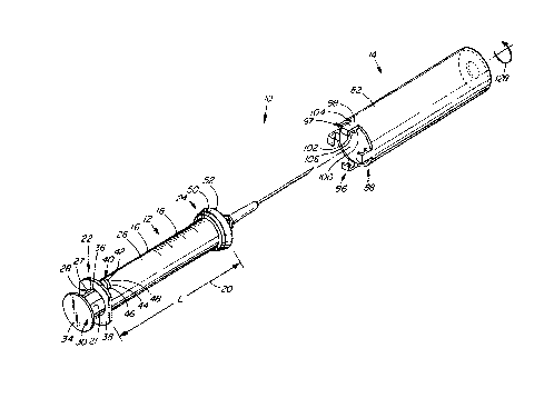
Figure 1 is a an oblique exploded view of an apparatus
according to a first embodiment of the invention;
ray
~, .:J
CA 02278697 1999-07-21
WO 98133539 PCT/CA97/00983
-8-
Figure 2 is a fragmented cross-sectional view of the
apparatus of Figure 1, in a position ready for
use;
Figure 3 is a fragmented cross-sectional view of the
apparatus of Figure 1, with a cover thereof shown
in a position in which a needle connected to the
apparatus is covered;
Figure 4 is a fragmented cross-sectional view of an
apparatus according to a second embodiment of the
invention; and
Figure 5 is a fragmented end view of the apparatus shown
in Figure 4.
DETAILED DESCRIPTION OF THE INVENTION
Referring to Figure 1, an apparatus according to
a first embodiment of the invention is shown generally at
10. The apparatus includes a syringe shown generally at 12
and a telescoping cover 14 formed over the syringe as
explained below.
Barrel
The syringe includes an elongated cylindrical
barrel 16 formed of transparent or clear plastic having a
plurality of graduations 18 and first length 20. The
barrel 16 has first and second end portions 22 and 24 and
an outer cylindrical surface 26 extending between the end
portions. The first end portion 22 has wall 27 defining a
circularly shaped plunger hole extending through the barrel
16 and having an opening 28 for receiving an elongated
plunger shown generally at 30. The plunger 30 has a shaft
21 operable to be received in the plunger opening 28 and
has a thumb-actuated pressure pad 34 which enables a user
to press the plunger 30 into the plunger opening 28 to
pressurize fluid within the plunger hole.
The first end portion 22 also has first and
second finger grip tabs 36 and 38 extending radially
outwardly of the plunger opening 28 to enable a user to
grasp the first end portion 22. Thus, the user is able to
grasp the finger grip tabs 36 and 38 with the forefinger
CA 02278697 1999-07-21
WO 98133539 PCT/CA97/00983
-9-
and middle finger and actuate the plunger 30 with the
thumb.
The first end portion 22 further has a radially
extending wedge-shaped tab 40 disposed on the outer
cylindrical surface 26, in spaced apart relation from the
first finger grip tab 36. The wedge shaped tab 40 extends
radially from the outer surface and has a caroming portion
42 having first) second and third caroming surfaces 44, 46
and 48.
The second end portion 24 has first and second
concentric annular portions 50 and 52 which extend about
the barrel 16. Referring to Figure 2, the first concentric
annular portion 50 has first and second radially planar
surfaces 54 and 56 and an inclined surface 58 extending
between the first and second radially planar surfaces 54
and 56. This inclined surface 58 thus extends at an obtuse
angle relative to the first inclined surface 58 and extends
at an acute angle relative to the second radially planar
surface 56. In this embodiment, the obtuse angle is
approximately 120 degrees.
The second concentric annular portion 52 has a
second inclined surface 60 and a third radially planar
surface 62. The second inclined surface 60 extends from
the second radially planar surface 56 at an acute angle of
approximately 45 degrees and the third radially planar
surface 65 extends in a radial plane at a most distal
position on the barrel 16. The second inclined surface 60
and the third radially planar surface 62 thus form a first
apex 64 projecting radially outwardly of the barrel 16.
The barrel 16 is terminated in a truncated
conical end 66 having a slightly tapered conduit 68. A
hypodermic needle assembly 70 includes a needle fastener 72
and a needle 74 having a needle point 76. The needle 74 is
connected to the needle fastener 72 and the needle fastener
72 is secured to the slightly tapered conduit 68 by a
friction-fit, in the convention manner. The needle
CA 02278697 1999-07-21
WO 98133539 PCTICA97100983
-10-
assembly 70 has an overall length 78 less than the length
20 of the barrel. ,
It will be appreciated therefore that it may be
said that the apparatus includes a barrel 16 having a first
end portion 22 for receiving a plunger 30 and a second end
portion 24 operable to hold a hypodermic needle 74.
Telescot~inct cover
Still referring to Figure 2, the barrel 16 and
telescoping cover 14 are formed together using a multiphase
injection moulding process. The telescoping cover 14 is
formed as a generally elongated tube 80 defined by a
cylindrical wall 82 of transparent plastic so that the
graduations 18 on the barrel 16 can be seen through the
telescoping cover 14. The cylindrical wall 82 has inside
and outside surfaces 84 and 86 and first and second end
portions 88 and 90 and has a length 92 slightly greater
than the length 20 of the barrel 16. The inside surface 84
defines a hole 94 in the tube 80 in which the barrel 16 is
received, the hole having a shape complementary to the
shape of the outer surface 26 of the barrel 16, which, in
this embodiment is circularly cylindrical.
Referring to Figure 1, a plurality of locking
members 96 are formed diametrically opposite each other and
extend axially relative to the cylindrical wall 82 at the
first end portion 88 thereof. Each locking member 97
includes a flexible portion 98, a pawl 100 and a hook 102.
The flexible portion 98 connects the pawl 100 to the
cylindrical wall 82 and has sufficient resilience to allow
the pawl 100 to have a little movement radially outwardly
and to return the pawl 100 to its original position after
such movement. The hook 102 is disposed most distal to
the cylindrical wall 82 and the pawl 100 and hook 102 are
spaced apart axially by a connecting wall 104. A
receptacle 106 is defined between the pawl 100 and the hook
102. The locking member 97 thus has a hook 102 spaced
apart from the pawl 100 to define a receptacle 106 between
the hook and the pawl.
__.__~~~._ .... ,
CA 02278697 1999-07-21
-11-
Referring to Figure 2, the pawl 100 has an
inclined surface 108 and a radially planar surface 110.
The inclined surface 108 extends at an angle of
approximately 45 degrees relative to the axis 112 of the
cylindrical wall 82. The radially planar surface 110 is
disposed more proximal to the first end portion 22 than the
inclined surface 108 and extends from the inclined surface
108 in a radial plane relative to the axis 112. The
radially planar surface 110 and inclined surface 108 thus
form a second apex 114 disposed radially inwardly of the
inside surface 84.
The hook 102 has first and second radially planar
surfaces 116 and 118 which extend in respective spaced
apart radial planes. An axially parallel surface 120
extends between the first and second radially planar
surfaces 116 and 118 at a distance such that the axially
parallel surface 120 is coplanar with the second apex 114.
The connection wall 104 has an inside surface 122
extending between the radially planar surface 110 of the
pawl 100 and the first radially planar surface 116 of the
hook 102. The receptacle 106 is thus defined by the
radially planar surface 110 of the pawl 100, the inside
surface 122 of the connecting wall 104 and the first
radially planar surface 116 of the hook 102. These
surfaces are dimensioned and positioned on the locking
member 97 such that the tab 40 is operable to be snugly
received in the receptacle 106. The pawl 100, connecting
wall 104 and hook 102 are contiguous with the cylindrical
wall 82 and thus the respective surfaces of these
components act as a wall porticn defining the receptacle
106.
The second end portion 90 cf the telescoping
cover includes a generally disk-shaped end wall 124
extending in a radial plane relative to the cylindrical
wall 82 and termi::ating the cylindrical wall. The end wall
124 has a central opening 126 therein, showr~ in broken
outline, for rece~;ving the needle assembly 70 therethrough.
r ~,~.%
y
CA 02278697 1999-07-21
WO 98133539 PCTICA97100983
-12-
Preferably, the central opening 126 is dimensioned to have
a diameter slightly greater than the diameter of the needle
fastener so that the central opening 126 is of minimal
size.
Operation
Referring to Figure 2, the apparatus is shown in
a position ready for use. In this position, the telescoping
cover 14 is in a non-extended position relative to the
barrel 16 and the tab 40 is received in the receptacle such
that the first, second and third camming surfaces 44, 46
and 48 are tightly received against the radially planar
surface 110 of the pawl 100, the inside surface 122 of the
connecting wall 104 and the first radially planar surface
116 of the hook 102. In this position, the telescoping
cover 14 is releasably locked to the barrel 16. It will
therefore be appreciated that the receptacle 106 on the
telescoping cover 14 and the tab 40 on the barrel 16 act as
a first releasable lock for releasably locking the
telescoping cover 14 to the barrel 16 when the telescoping
cover 14 is in a non-extended position.
It will be appreciated that syringes are provided
separately from the needle assembly 70 and that the needle
assembly 70 is removed from a separate package and fastened
to the barrel 16 by placing the needle fastener 72 over the
slightly tapered conduit 68, whereby the needle assembly is
held thereon by a friction-fit. The slightly tapered
conduit 68 extends through the central opening 126 in the
end wall 124 to facilitate fastening of the needle assembly
70. Thus, the telescoping cover 14 has a wall 124 defining
an opening 126 through which the hypodermic needle extends
74, when the telescoping cover 14 is in a non-extended
position.
The syringe 12 is then used in the conventional
manner to inject medication into a patient or to draw fluid
from the patient.
After use of the syringe 12 , the outer surface 86
of the telescoping cover 14 is gripped with one hand while
CA 02278697 1999-07-21
WO 98133539 PCTICA97I00983
-13-
the finger grip tabs 36 and 38 are grasped by the other
hand and the telescoping cover 14 is rotated relative to
the barrel 16 in the direction of arrow 128 shown in Figure
1. Referring to Figure 2, such rotation releases the tab
40 from the receptacle 106 allowing the telescoping cover
14 to be positioned such that the tab 40 is between
adjacent locking members (97), whereupon the telescoping
cover 14 may be telescopically extended relative to the
barrel 16 . The tab 40 is thus releasably j ammed in the
receptacle 106 to secure the telescoping cover 14 to the
barrel 16 until the telescoping cover 14 is rotated
relative to the barrel 16 to release the tab 40 from the
receptacle 106, thereby unlocking the telescoping cover 14
relative to the barrel 16 and permitting extension of the
telescoping cover 14 relative to the barrel 16.
The outer surface 26 of the barrel 16 and the
hole 94 in the tubular telescoping cover 14 having a shape
complementary to the shape of the cylindrical surface 26 of
the barrel 16 acts to guide the telescoping cover 14 in
axial movement relative to the barrel 16 as the telescoping
cover 14 is extended relative to the barrel 16. Guiding of
the telescoping cover 14 is enhanced by the apex 114 of the
pawl and the axially parallel surface 120 of the hook 102
riding on the outer surface 26 of the barrel 16 and by the
inside surface 84 of the telescoping cover 14 riding on the
apex 64 of the second annular portion 52 as the telescoping
cover 14 is extended relative to the barrel 16.
When the telescoping cover 14 has been extended
sufficiently, the pawl 100 will come in contact with the
first annular portion 50. Further axial movement of the
telescoping cover 14 causes the inclined surface 108 on the
pawl 100 to be pushed radially outwardly by the first
inclined surface 58 on the first annular portion 50 as the
inclined surface 108 on the pawl 100 rides over the
inclined surface 58 on the first annular portion 50.
When the apex 114 of the pawl 100 clears the
second radially planar surface 56 of the first annular
CA 02278697 1999-07-21
WO 98/33539 PCT/CA97100983
-14-
portion 50, the resilience of the flexible portion 98
returns the pawl 100 to its original position, whereupon
the inclined surface 108 on the pawl 100 contacts the
inclined surface 60 on the second annular portion 52 and
the radially planar surface 110 on the pawl 100 abuts the
second radially planar surface 56 of the first annular
portion 50 as shown in Figure 3. In this position, the
second radially planar surface 56 of the first annular
portion 50 interferes with the radially planar surface 110
on the pawl 100 and prevents counter movement of the
telescoping cover 14 in a direction tending to retract the
telescoping cover 14 relative to the barrel 16. In this
position, because the locking members (97) are located at
the first end portion 88 of the telescoping cover 14 and
because the f first and second annular portions 50 and 52 are
located at the second end portion 24 of the barrel 16, the
telescoping cover 14 is fully extended relative to the
barrel 16. When the telescoping cover 14 portion is fully
extended in this manner, because the length 92 of the
telescoping cover 14 is greater than the length 78 of the
needle assembly 70, the end wall 124 is positioned beyond
the needle point 76 of the hypodermic needle 74, whereupon
the needle is fully covered and the user is guarded against
needle prick injuries. Thus, it may be said that the
apparatus includes a telescoping cover 14 engaged with the
barrel 16, operable to extend relative to the barrel 16 to
cover the hypodermic needle 74.
The user cannot retract the telescoping cover 14
relative to the barrel 16 due to the interference between
the radially planar surface 110 on the pawl 100 and the
radially planar surface 56 on the first annular portion 50.
The second radially planar surface 56 on the first annular
portion 50 thus acts as an interfering surface operable to
interfere with movement of the pawl 100 when the
telescoping cover 14 is forced in a direction tending to
retract the telescoping cover 14 relative to the barrel 16
after the telescoping cover has been sufficiently extended
CA 02278697 1999-07-21
WO 98133539 PCT/CA97/00983
-15-
relative to the barrel 16 to cover the needle 74. The pawl
100 and the first annular portion 50 thus act as a second
lock for permanently locking the telescoping cover 14 in an
extended position when the telescoping cover 14 is in an
extended position fully covering the needle 74.
The telescoping cover 14 is supported in the
extended position by the mating of the inclined surfaces 60
and 108 on the pawl 100 and the second annular portion 52
and by the mating of the second annular surface 56 with the
radially planar surface 110 on the pawl 100. Axial
movement is prevented by the inclined surfaces 60 and 108
mating with each other and by the interference between the
second radially planar surface 56 and the radially planar
surface 110 on the pawl 100. Radiamovement is prevented
by the pawl 100 being disposed on diametrically opposite
sides of the telescoping cover 14. Thus) the inclined
surface 60 of the second annular portion 52 acts as a
support surface complementary to the inclined surfaces 108
on the pawls 100 for mating with the inclined surfaces 108
on the pawls 100 to support the telescoping cover 14 in an
extended position in which the needle 74 is covered.
Second Embodiment
Referring to Figure 4, an apparatus according to
a second embodiment of the invention is shown generally at
150. The apparatus includes a telescoping cover 14 and
barrel 16 having components similar to that as shown in the
first embodiment, which are designated by the same
numerical references used in the description of the
apparatus according to the first embodiment.
The apparatus according to the second embodiment
differs from the apparatus according to the first
embodiment in that in place of the locking members, the
apparatus according to the second embodiment includes a
plurality of hooks 154 disposed on diametrically opposite
locations around the first end portion 88 of the
cylindrical wall 82, a mating hook ring 156 is formed on
CA 02278697 1999-07-21
WO 98!33539 PCT/CA97100983
-16-
the second end portion 90 of the barrel 16 and a hook 157
is formed on the first end portion 22 of the barrel 16.
The hooks 154 on the telescoping cover include a
radially inwardly extending wall 158, an axially parallel
wall 160 and a barb 162. The radially inwardly extending
wall 158 extends radially inwardly from the cylindrical
wall 82. The axially parallel wall 160 extends parallel to
the axis 164 a short distance and the barb 162 terminates
the axially parallel wall 160. The barb 162 has an
inclined surface 166 and a radially planar surface 168.
The inclined surface 166 extends outwardly toward the
axially parallel wall 160 and the radially planar surface
168 extends radially inward from the inclined surface 166.
The hook ring 156 extends about the second end
portion 24 of the barrel 16 and has a radially outwardly
extending annular wall 170, a concentric annular wall 172
concentric with the barrel 16 and a lip 174 terminating the
circular wall. The lip 174 has an inclined surface 176
converging toward the second end portion 24 of the barrel
16 and terminated in a radially planar surface 178
extending radially outwardly of the inclined surface 176.
An annular receptacle 180 is thus formed between
the radially planar surface 178 of the hook ring 156 and
the annular wall 170 of the hook ring. The annular wall
170 of the hook ring 156 and the radially extending walls
158 of the hooks 154 are dimensioned such that the barbs
162 are operable to be snugly received between the
concentric annular wall 172 and the outer surface 26 of the
barrel 16 and between the radially outwardly extending
annular wall 170 and the radially planar surface 178 on the
hook ring 156.
The hook 157 on the first end portion 22 has a
shape similar to that of the hook ring 156 at the second
end portion 24 with the exception that the hook 157 on the
first end portion 22 is arcuate and extends through an
angle 181 of approximately 10 degrees, seen best in Figure
5. The hook includes a radially extending wall 182 and an
......._~.....~......~..........w_..~~.... T. . . .... .. .. _....,. " .
.,..... ..
CA 02278697 1999-07-21
-17-
axially parallel wall 184. The radially extending wall 182
serves to space the axially parallel wall 184 from the
outer surface 26 of the barrel 16 to form an arcuate wedge-
shaped receptacle 186 operable to receive and grip one of
the hooks 154 formed in the telescoping covers.
Operation
Referring to Figure 4, a retracted position of
the cover 14, wherein the apparatus is ready for use is
shown in fragmented, broken outline. In this position, the
telescoping cover 14 is in a non-extended position relative
to the barrel 16 and one of the hooks 154 is received in
the receptacle 186 such that the hook is tightly received
against the axially extending wall 182 of the hook on the
barrel 16. In this position, the telescoping cover is
releasably locked to the barrel. It will therefore be
appreciated that the receptacle 186 formed by the hook 157
on the barrel 16 and the hook 154 on the telescoping cover
14 act as a first releasable lock for releasably locking
the telescoping cover 14 to the barrel 16 when the
telescoping cover 14 is in a non-extended position.
After use of the syringe, the outer surface 26 of
the telescoping cover 14 is gripped with one hand while the
finger grip tabs are 36 and 38 grasped by the other hand
and the telescoping cover 14 is rotated relative to the
barrel 16 to release the hook 154 from the receptacle 186.
The telescoping cover may then be positioned such that the
barrel hook 157 is between adjacent hooks 154, whereupon
the telescoping cover 14 may be telescopically extended
relative to the barrel 16. The hook 154 is thus releasably
jammed in the receptacle 186 to secure the telescoping
cover 14 to the barrel 16 until the telescoping cover 14 is
rotated relative to the barrel 16 to release the hook 154
from the receptacle 186, thereby unlocking the telescoping
cover 14 relative to the barrel 16 and permitting extension
of the telescoping cover 14 relative to the barrel 16.
Guiding of the telescoping cover 14 is enhanced
by the aaially extending walls 160 of the hooks 154 riding
LZ
.., C'nL
W
lyvlW
~~,rt.Y
\o
CA 02278697 1999-07-21
WO 98!33539 PCTICA97/00983
-18-
on the outer surface 26 of the barrel 16, while the inside
surface 84 of the telescoping cover 14 rides on the annular
concentric wall 172 of the hook ring 156.
When the telescoping cover 14 has been extended
sufficiently, the inclined surfaces 176 and 166 of the hook
ring 156 and the hooks 154 engage and resiliently deform as
the barbs 162 of the hooks 154 are forced into the
receptacle 180 formed between the radially planar surface
178 of the hook ring and the annular wall 170 of the hook
ring 156.
In this position, the radially planar surfaces
178 and 168 abut each other whereupon the radially planar
surface 178 on the hook ring 156 interferes with the
radially planar surface 168 on the hooks 154 and prevents
counter movement of the telescoping cover 14 in a direction
tending to retract the telescoping cover 14 relative to the
barrel 16. In this position) the telescoping cover 14 is
fully extended relative to the barrel. When the
telescoping cover is fully extended in this manner, because
the length of the telescoping cover is greater than the
length of the needle assembly, the needle is fully covered
and the user is guarded against needle prick injuries.
Furthermore, the user cannot retract the telescoping cover
14 relative to the barrel 16. The hook ring 156 and the
hooks 154 thus act as a second lock for permanently locking
the telescoping cover 14 in an extended position when the
telescoping cover 14 is in an extended position fully
covering the needle 74.
The telescoping cover 25 is supported in the
extended position by the mating of the inside surface 84 of
the telescoping cover 14 with the concentric annular wall
172 of the hook ring 156 and the tight grip on the hooks
154 provided by the hook ring 156. Thus, the concentric
annular wall 172 of the hook ring 156 acts as a support
surface for supporting the telescoping cover 14 in an
extended position in which the needle 74 is covered.
~.._._..~....., ~..-- .. r
CA 02278697 1999-07-21
WO 98/33539 PCT1CA97100983
-19-
It is a particular advantage of the invention
that after the use of the syringe, the telescoping cover 14
may simply and quickly be rotated relative to the barrel 16
and drawn outwardly of the barrel 16, or telescopically
extended relative to the barrel 16, in a direction away
from the point 76 of the needle 74 until the needle is
covered. Thus, the user's hands are kept away from the
needle point 76 and there is no movement which would drive
the needle 74 into the user's hand or body. Rather, all
movement is away from the needle point 76. Thus, the
operation of the apparatus presents little risk to the user
and after operation of the device the risk of needle prick
injuries is small as needle 74 is completely covered.
While specific embodiments of the invention have
been described and illustrated, such embodiments should be
considered illustrative of the invention only and not as
limiting the invention as construed in accordance with the
accompanying claims.