Sélection de la langue

Search

Sommaire du brevet 2280036 

Énoncé de désistement de responsabilité concernant l'information provenant de tiers

Une partie des informations de ce site Web a été fournie par des sources externes. Le gouvernement du Canada n'assume aucune responsabilité concernant la précision, l'actualité ou la fiabilité des informations fournies par les sources externes. Les utilisateurs qui désirent employer cette information devraient consulter directement la source des informations. Le contenu fourni par les sources externes n'est pas assujetti aux exigences sur les langues officielles, la protection des renseignements personnels et l'accessibilité.

Disponibilité de l'Abrégé et des Revendications

L'apparition de différences dans le texte et l'image des Revendications et de l'Abrégé dépend du moment auquel le document est publié. Les textes des Revendications et de l'Abrégé sont affichés :

  • lorsque la demande peut être examinée par le public;
  • lorsque le brevet est émis (délivrance).
(12) Demande de brevet: (11) CA 2280036
(54) Titre français: STABILISATEUR POUR ECHELLE
(54) Titre anglais: LADDER STABILIZING DEVICE
Statut: Réputée abandonnée et au-delà du délai pour le rétablissement - en attente de la réponse à l’avis de communication rejetée
Données bibliographiques
Abrégés

Abrégé français

L'invention porte sur un stabilisateur pour échelle de fixant à l'extrémité inférieure d'un montant de l'échelle et réglable par incréments pour s'adapter aux irrégularités de la surface sur laquelle repose l'échelle. Le dispositif présente une embase comportant des étais avant et arrière espacés conférant une bonne assise à l'échelle. L'embase peut pivoter entre sa position de soutien de l'échelle et une position de rangement.


Abrégé anglais


A ladder stabilizing device (10) is attached to the lower end of a ladder rail
(S). The device (10) is incrementally adjustable to compensate for
irregularities in a ladder supporting surface and has a support base (12)
includes spaced apart front and rear legs (18, 20) to provide sound footing
for the ladder (L). The support base (12) is pivotal between a ladder (L)
supporting position and a storage position.

Revendications

Note : Les revendications sont présentées dans la langue officielle dans laquelle elles ont été soumises.


6
Claims:
1. A stabilizing device for a straight ladder having elongate
parallel laterally spaced apart side rails including upper and lower end
portions
and a plurality of longitudinally spaced apart rungs extending laterally
between
and connecting said side rails, the ladder being adapted for use in a
forwardly and
upwardly inclined position with its upper end portion resting upon a
supporting
structure, said stabilizing device comprising a base member having an upwardly
extending front leg and an upwardly extending rear leg spaced from said front
leg,
said front leg being substantially longer than said rear leg, a forwardly and
upwardly inclined carrying member connected to and extending between the
upper ends of said rear leg and said front leg, an elongate support member
mounted on said base member for pivotal movement about a laterally extending
axis and relative to said base member, a connecting member mounted on said
support member and having a socket defining portion for receiving the lower
end
portion of an associated side rail, and securing means for releasably
attaching
said connecting member to the associated side rail.
2. A stabilizing device for a straight ladder as set forth in claim 1
wherein said support member is mounted on said carrying member intermediate
said front leg and said rear leg.
3. A stabilizing device for a straight ladder as set forth in claim 2
wherein said axis is located closer to said front leg than to said rear leg.
4. A stabilizing device for a straight ladder as set forth in claim 1
wherein said socket defining portion of said connecting member is laterally
offset
relative to said support member.
5. A stabilizing device for a straight ladder as set forth in claim 4
wherein said socket defining portion is rearwardly offset relative to said
support
member.

7
6. A stabilizing device for a straight ladder as set forth in claim 1
wherein said connecting member is mounted on said support member for
adjustable positioning along said support member and said device includes
retaining means for releasably securing said connecting member in a selected
position of adjustment relative to said support member.
7. A stabilizing device for a straight ladder as set forth in claim 6
wherein said connecting member is incrementally adjustable relative to said
support member and said retaining means comprises a retaining pin received
within apertures in said connecting member and said support member.
8. A stabilizing device for a straight ladder as set forth in claim 7
wherein said support member has a bifurcated lower end portion straddling said
carrying member and said device includes a pivot pin extending through said
bifurcated lower end and said carrying member and defining said axis.
9. A stabilizing device for a straight ladder as set forth in claim 8
wherein said base member is pivotally moveable relative to said support member
between an active position wherein said carrying member is disposed with its
longitudinal axis extending in a generally transverse direction relative to
the
longitudinal axis of said support member and a storage position wherein the
longitudinal axis of said carrying member is generally axially parallel to the
longitudinal axis of said support member.
10. A stabilizing device for a straight ladder as set forth in claim 8
wherein said support member has an upwardly extending shank portion and said
bifurcated lower end portion is laterally offset relative to said shank
portion.
11. A stabilizing device for a straight ladder as set forth in claim 1
wherein said securing means comprises a clamping fastener threadably engaged
with said connecting member.

8
12. A stabilizing device for a straight ladder as set forth in claim 1
wherein said connecting member includes a front wall having a slot
therethrough
defining a portion of said socket.
13. A stabilizing device as set forth in claim 12 wherein said
socket has a generally T-shaped cross-section.
14. A stabilizing device for a straight ladder as set forth in claim 13
wherein said socket defined by said connecting member is rearwardly and
laterally offset relative to said support member.
15. A stabilizing device for a straight ladder having elongate
parallel laterally spaced apart side rails including upper and lower end
portions
and a plurality of longitudinally spaced apart rungs extending laterally
between
and connecting said side rails, the ladder being adapted for use in a
forwardly and
upwardly inclined position with its upper end portion resting upon a
supporting
structure, said stabilizing device comprising a base member having an upwardly
extending rear leg, an upwardly extending front leg having a greater length
than
said rear leg and spaced forwardly of said rear leg, and a forwardly and
upwardly
inclined carrying member integrally connected to and extending between the
upper ends of said rear leg and said front leg, an elongate longitudinally
extending support member having a bifurcated lower end portion straddling said
carrying member, a pivot pin extending through said bifurcated lower end
portion
and said carrying member and securing said support member to said base
member for pivotal movement about a laterally extending axis and relative to
said
base member, a connecting member mounted on said supporting member for
sliding movement longitudinally of said supporting member between a plurality
of
positions of adjustment relative to said supporting member, said connecting
member defining a socket for receiving the lower end of an associated one of
the
side rails therein, retaining means for releasably securing said connecting
member in a selected position of adjustment relative to said support member,
and
means for releasably securing said connecting member to the associated one of
the side rails.
16. A stabilizing device for a straight ladder as set forth in claim 15
wherein said socket defined by said connecting member is laterally offset
relative
to said support member.

9
17. A stabilizing device for a straight ladder as set forth in claim 16
wherein said socket defined by said connecting member is rearwardly offset
relative to said support member.
18. A stabilizing device for a straight ladder as set forth in claim 17
wherein said connecting member includes a front wall portion and said socket
is
partially defined by a longitudinally extending slot opening through said
front wall
portion.
19. A stabilizing device for a straight ladder as set forth in claim 18
wherein said socket has a generally T-shaped cross-section.

10
20. A stabilizing device for a straight ladder as set forth in claim 17
wherein said base member is supported for pivotal movement relative to said
support member between an active position wherein said carrying member is
disposed in transverse relationship to said support member and a storage
position
wherein said carrying member is disposed in generally parallel relation to
said
support member.
21. A stabilizing device for a straight ladder as set forth in claim 15
wherein said retaining means comprises a clamping fastener threadably engaging
said connecting member for clampingly engaging the lower end of an associated
one of the side rails received within said socket.
22. A stabilizing device for a straight ladder as set forth in claim 15
wherein said support member has an upwardly extending shank, said connecting
member is mounted on said shank, and said bifurcated lower end portion is
laterally offset relative to said shank.

Description

Note : Les descriptions sont présentées dans la langue officielle dans laquelle elles ont été soumises.

CA 02280036 1999-08-06
WO 97/30260 PCT/US96/02085
1
LADDER STABILIZING DEVICE
BACKGROUND OF THE INVENTION
This invention relates in general to ladder safety devices and deals
more particularly with an improved stabilizing device for a ground-supported
straight ladder.
A ground supported ladder of the type with which the present
invention is concerned is used in an inclined position with its upper end
portion
resting on or against a suitable support. When a downwardly directed force is
applied to the ladder by someone standing on it there is a nature tendency for
the
base of the ladder to move in a horizontal direction away from the supporting
surface. Most serious accidents involving ladders of this type can be
attributed to
failure to provide a sound ladder footing. Long straight ladders and
particularly
extension ladders are inherently unstable when supported on uneven ground.
When such a ladder is used on irregular or sloping surfaces it is common
practice
to block or shim the ladder to compensate for the irregularity of the
supporting
surface. This is an extremely dangerous practice, but in many instances the
practice cannot be avoided. This is particularly true where there is no
provision for
adjusting the effective length of the ladder side rails.
Accordingly, it is the general aim of the present invention to provide an
improved ladder stabilizing device which is geometrically designed to provide
a
wide support base to assure firm footing for a straight ladder. It is a
further aim of
the invention to provide a ladder stabilizing device which may be readily
adjusted
to compensate for irregularities in the ladder supporting surface and may be
collapsed to a storage position for convenient handling and storage.
SUMMARY OF THE INVENTION
In accordance with the present invention, a stabilizing device is
provided for a straight ladder having elongate parallel laterally spaced apart
side
rails including upper and lower ends and a plurality of spaced apart rungs
extending laterally between and connecting the side rails. Such a ladder is
normally arranged in a forwardly and upwardly inclined position with the upper

CA 02280036 1999-08-06
WO 97/30260 PCT/US96l02085
2
end portion resting on a supporting structure. The stabilizing device
comprises a
base member having an upwardly extending front leg and an upwardly extending
rear leg spaced from the front leg. The base member further includes a
forwardly
and upwardly inclined carrying member which is connected to and extends
between the upper ends of the rear leg and the front leg. An elongate support
member is mounted on the base member for pivotal movement about a laterally
extending axis relative to the base member and carries a connecting member
which defines a socket for receiving the lower end of an associated side rail.
A
means is provided for releasably securing the associated side rail to the
connecting member.
BRIEF DESCRIPTION OF THE DRAWING
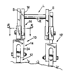
Fig. 1 is a fragmentary front elevational view of a straight ladder
shown supported on an uneven surface by a pair of stabilizing devices
embodying
the present invention.
Fig. 2 is a somewhat enlarged fragmentary side elevational view of a
ladder stabilizing device embodying the present invention.
Fig. 3 is a fragmentary front elevational view of the device.
Fig. 4 is a fragmentary top plan view of the device shown in Fig. 2.
Fig. 5 is a somewhat enlarged fragmentary sectional view taken
along the line 5-5 of Fig. 1.
Fig. 6 is a fragmentary front elevational view of another ladder
stabilizing device embodying the present invention.
DETAILED DESCRIPTION OF PREFERRED EMBODIMENT
Turning now to the drawing and referring first to Fig. 1 a pair of ladder
stabilizing devices embodying the present invention and indicated generally at
10
and 10' are shown attached to and supporting a straight ladder designated
generally by the letter L. The illustrated ladder L is a conventional
extension
ladder and has a main section M which includes a pair of elongate parallel
laterally spaced apart side rails S, S. The side rails have upper and lower
ends,
but only the lower ends are shown. A plurality of longitudinally spaced apart
rungs
R, R extend laterally between and connect the side rails S, S. The illustrated
ladder L is an extension ladder and also includes an extendible section (not
shown) which is generally telescopically engaged with the main section M. The
ladder L is adapted for use in a forwardly and upwardly inclined position with
the
~ ___..__._ ._ .. T .

CA 02280036 1999-08-06
WO 97/30260 PCT/US96/02085
3
upper end portion of the ladder resting upon a suitable supporting structure
{not
shown). The stabilizing devices 10, 10' are adjustable and particularly
adapted to
support a ladder, such as the ladder L, in a stable position both on a level
supporting surface and on uneven ground, as shown in Fig. 1 and as will be
hereinafter evident from the further description which follows.
The illustrated ladder stabilizing devices 10 and 10' are preferable
fabricated from a light weight metal, such as aluminum, and are substantially
identical to each other, but of opposite hand for a reason which will be
hereinafter
evident.
Further referring to the drawings and particularly to Figs. 2-4, the left
hand device 10 is illustrated and essentially comprises a base member
indicated
generally by the numeral 12, a support member pivotally mounted on the base
member and designated generally by the numeral 14 and a connecting member
indicated generally at 16 and adjustably secured to the support member 14.
Considering the ladder stabilizing device 10 in further detail, the
base member 12 comprises a unitary structure and includes an upwardly
extending rear leg 18 and an upwardly extending front leg 20, which is
somewhat
longer than the rear leg, and a forwardly and upwardly inclined carrying
member
22 integrally connected to and extending between the upper ends of the rear
leg
18 and the front leg 20. Preferably and as shown the legs 18 and 20 have
friction
pads 23, 23 attached to the bottom surfaces thereof, as best shown in Figs. 2
and
4.
The support member 14 has a longitudinally upwardly extending
elongate shank 25 and a bifurcated lower end portion or cievis 24 which
straddles
the carrying member 22. The lower end portion of the support member 14 is
pivotally connected to the carrying member 22 by a pivot pin or bolt 26 which
extends laterally through both the bifurcated lower end portion 24 and the
carrying
member 22. Preferably, and as best shown in Fig. 2, the axis of the pivot pin
26,
indicated at 28, is located closer to the front leg 20 than to the rear leg
18. A series
of longitudinally spaced apart cylindrical holes 30, 30 extend transversely
through
the upwardly extending shank 25 for a purpose which will be hereinafter
further
evident.
The connecting member 16 is slidably supported on the shank 25
and is formed as either a right or left handed part, as shown in Fig. 1. It
has a
generally rectangular collar portion 32 and a socket defining portion 34 which
is
both laterally and rearwardly offset relative to the collar portion 32, as
best shown

CA 02280036 1999-08-06
WO 97/30260 PCT/US96/02085
4
in Figs. 3 and 5. The collar portion 32 has a rectangular bore 36 extending
through it which receives and substantially complements the shank 25 on the
support member 14. Laterally aligned cylindrical holes 38, 38 substantially
equal
in size to the holes 30, 30 open through opposite sides of the collar portion
32 for
registry with a selected one of the holes 30, 30 to receive a locking pin 40
for
releasably securing the collar in a selected one of a plurality of incremental
positions of adjustment along the shank 25. The Pocking pin may take various
forms. However, the illustrated locking pin 40 includes a spring ball decent
at its
free end for releasably retaining the pin in assembly with the collar 34.
The socket defining portion 34 includes an upwardly open blind
socket 42 partially defined by a slot 44 in the front wall of the socket
defining
portion 34. The socket has a generally T-shaped cross-section as viewed from
above (Figs. 3 and 5) and is particularly adapted to receive the lower end of
a
metal ladder having side rails S, S of channel shaped cross-section. A
clamping
fastener 46 threadably engaged in the rear wall of the socket defining portion
34
for clampingly engaging the lower end portion of a ladder sidewall S to
releasably
retain the device 10 in assembly with the ladder.
In Fig. 5 the lower end of a side rail of the extension ladder L is
shown clamped within the socket 42, the extendible portion of the ladder being
shown in broken lines. When the device 10 is attached to a ladder of the type
shown the extendible portion of the ladder may be moved to its fully lowered
position without removing the device from the ladder. It is for this reason
that the
socket defining portion is offset relative to the collar portion 32. The
geometry of
the base member 12 and the manner in which the support member 14 is
connected to the base member provide a sound support base for the ladder L.
The support base 12 is pivotally moveable between an active
position wherein the carrying member 22 extends generally transversely of the
support member 14 and a storage position wherein the carrying member is
disposed in generally axially parallel relation to the support member, as it
appears
in broken fines in Fig. 2.
Fig. 6 illustrates another ladder stabilizing device embodying the
present invention and indicated generally at 10a. The illustrated device 10a
is
similar in most respects to the device 10 previously described and parts which
correspond to parts of the previously described device bear the same reference
numeral and a letter a suffix and will not be hereinafter described in detail.
T .. ~ .____._... ... T .. _ ___._.._.

CA 02280036 1999-08-06
WO 97/30260 PCT/US96/02085
The device 10a differs from the device 10 in the construction and
arrangement of the support member 14a. Specifically, the support member 14a
has an upwardly extending shank portion 25a which carries the connecting
member 16a, as previously described. The support member 14a also has a
5 bifurcated lower end portion indicated at 24a which is laterally offset
relative to the
shank portion 25a.
The ladder stabilizing device 10a, which comprises the presently
preferred structure, is used in combination with a substantially identical
ladder
stabling device of opposite hand to support a straight ladder in the manner
hereinbefore described. However, because of the laterally offset arrangement
of
the base members 12 the devices provide a somewhat wider support base for a
ladder and provide a greater degree of lateral stability.

Dessin représentatif
Une figure unique qui représente un dessin illustrant l'invention.
États administratifs

2024-08-01 : Dans le cadre de la transition vers les Brevets de nouvelle génération (BNG), la base de données sur les brevets canadiens (BDBC) contient désormais un Historique d'événement plus détaillé, qui reproduit le Journal des événements de notre nouvelle solution interne.

Veuillez noter que les événements débutant par « Inactive : » se réfèrent à des événements qui ne sont plus utilisés dans notre nouvelle solution interne.

Pour une meilleure compréhension de l'état de la demande ou brevet qui figure sur cette page, la rubrique Mise en garde , et les descriptions de Brevet , Historique d'événement , Taxes périodiques et Historique des paiements devraient être consultées.

Historique d'événement

Description Date
Inactive : CIB de MCD 2006-03-12
Demande non rétablie avant l'échéance 2004-02-13
Inactive : Morte - RE jamais faite 2004-02-13
Réputée abandonnée - omission de répondre à un avis sur les taxes pour le maintien en état 2004-02-13
Inactive : Abandon.-RE+surtaxe impayées-Corr envoyée 2003-02-13
Inactive : Grandeur de l'entité changée 2003-01-31
Inactive : Page couverture publiée 1999-10-14
Inactive : CIB en 1re position 1999-10-12
Inactive : Supprimer l'abandon 1999-09-16
Inactive : Notice - Entrée phase nat. - Pas de RE 1999-09-14
Demande reçue - PCT 1999-09-11
Réputée abandonnée - omission de répondre à un avis sur les taxes pour le maintien en état 1999-02-15
Demande publiée (accessible au public) 1997-08-21

Historique d'abandonnement

Date d'abandonnement Raison Date de rétablissement
2004-02-13
1999-02-15

Taxes périodiques

Le dernier paiement a été reçu le 2003-01-23

Avis : Si le paiement en totalité n'a pas été reçu au plus tard à la date indiquée, une taxe supplémentaire peut être imposée, soit une des taxes suivantes :

  • taxe de rétablissement ;
  • taxe pour paiement en souffrance ; ou
  • taxe additionnelle pour le renversement d'une péremption réputée.

Les taxes sur les brevets sont ajustées au 1er janvier de chaque année. Les montants ci-dessus sont les montants actuels s'ils sont reçus au plus tard le 31 décembre de l'année en cours.
Veuillez vous référer à la page web des taxes sur les brevets de l'OPIC pour voir tous les montants actuels des taxes.

Historique des taxes

Type de taxes Anniversaire Échéance Date payée
Rétablissement (phase nationale) 1999-08-06
Taxe nationale de base - petite 1999-08-06
TM (demande, 2e anniv.) - petite 02 1998-02-13 1999-08-06
TM (demande, 3e anniv.) - petite 03 1999-02-15 1999-08-06
TM (demande, 4e anniv.) - petite 04 2000-02-14 2000-01-14
TM (demande, 5e anniv.) - petite 05 2001-02-13 2001-01-25
TM (demande, 6e anniv.) - petite 06 2002-02-13 2002-01-24
TM (demande, 7e anniv.) - générale 07 2003-02-13 2003-01-23
Titulaires au dossier

Les titulaires actuels et antérieures au dossier sont affichés en ordre alphabétique.

Titulaires actuels au dossier
WILLIAM MOSELSKY
Titulaires antérieures au dossier
S.O.
Les propriétaires antérieurs qui ne figurent pas dans la liste des « Propriétaires au dossier » apparaîtront dans d'autres documents au dossier.
Documents

Pour visionner les fichiers sélectionnés, entrer le code reCAPTCHA :


Pour visualiser une image, cliquer sur un lien dans la colonne description du document. Pour télécharger l'image (les images), cliquer l'une ou plusieurs cases à cocher dans la première colonne et ensuite cliquer sur le bouton "Télécharger sélection en format PDF (archive Zip)" ou le bouton "Télécharger sélection (en un fichier PDF fusionné)".

Liste des documents de brevet publiés et non publiés sur la BDBC .

Si vous avez des difficultés à accéder au contenu, veuillez communiquer avec le Centre de services à la clientèle au 1-866-997-1936, ou envoyer un courriel au Centre de service à la clientèle de l'OPIC.


Description du
Document 
Date
(aaaa-mm-jj) 
Nombre de pages   Taille de l'image (Ko) 
Dessin représentatif 1999-10-13 1 6
Dessins 1999-08-05 2 47
Revendications 1999-08-05 5 198
Abrégé 1999-08-05 1 46
Description 1999-08-05 5 271
Avis d'entree dans la phase nationale 1999-09-13 1 207
Rappel - requête d'examen 2002-10-15 1 115
Courtoisie - Lettre d'abandon (requête d'examen) 2003-04-23 1 167
Courtoisie - Lettre d'abandon (taxe de maintien en état) 2004-04-12 1 175
PCT 1999-08-05 9 314