Sélection de la langue

Search

Sommaire du brevet 2280056 

Énoncé de désistement de responsabilité concernant l'information provenant de tiers

Une partie des informations de ce site Web a été fournie par des sources externes. Le gouvernement du Canada n'assume aucune responsabilité concernant la précision, l'actualité ou la fiabilité des informations fournies par les sources externes. Les utilisateurs qui désirent employer cette information devraient consulter directement la source des informations. Le contenu fourni par les sources externes n'est pas assujetti aux exigences sur les langues officielles, la protection des renseignements personnels et l'accessibilité.

Disponibilité de l'Abrégé et des Revendications

L'apparition de différences dans le texte et l'image des Revendications et de l'Abrégé dépend du moment auquel le document est publié. Les textes des Revendications et de l'Abrégé sont affichés :

  • lorsque la demande peut être examinée par le public;
  • lorsque le brevet est émis (délivrance).
(12) Demande de brevet: (11) CA 2280056
(54) Titre français: BOITE D'APPAREIL STANDARD A DEUX COMPARTIMENTS
(54) Titre anglais: A DIVIDED STANDARD DEVICE BOX
Statut: Réputée abandonnée et au-delà du délai pour le rétablissement - en attente de la réponse à l’avis de communication rejetée
Données bibliographiques
(51) Classification internationale des brevets (CIB):
  • H02G 03/08 (2006.01)
(72) Inventeurs :
  • JUSTINIANO, JOSEPH G. (Etats-Unis d'Amérique)
  • TANSI-GLICKMAN, SELIN (Etats-Unis d'Amérique)
  • STEWART, STEPHEN (Etats-Unis d'Amérique)
  • ESTANISLAO, DANILO F. (Etats-Unis d'Amérique)
(73) Titulaires :
  • LEVITON MANUFACTURING CO., INC.
(71) Demandeurs :
  • LEVITON MANUFACTURING CO., INC. (Etats-Unis d'Amérique)
(74) Agent: SMART & BIGGAR LP
(74) Co-agent:
(45) Délivré:
(22) Date de dépôt: 1999-08-10
(41) Mise à la disponibilité du public: 2000-02-19
Requête d'examen: 2004-07-28
Licence disponible: S.O.
Cédé au domaine public: S.O.
(25) Langue des documents déposés: Anglais

Traité de coopération en matière de brevets (PCT): Non

(30) Données de priorité de la demande:
Numéro de la demande Pays / territoire Date
09/136,579 (Etats-Unis d'Amérique) 1998-08-19

Abrégés

Abrégé anglais


To separate the chamber of a standard device box into two
compartments, one for high voltage power conductors and the other for low
power
signal conductors a deflectable isolation barrier is employed. In a first form
the
barrier, its supporting means and attaching means are formed as an integral
unit
and fastened to the inside surface of a wall plate. The barrier takes a
position in
the box based upon the depth of the box. In a second form the deflectable
isolation barrier is formed as an extension of the side wall of a box insert
to be
placed in the device box.

Revendications

Note : Les revendications sont présentées dans la langue officielle dans laquelle elles ont été soumises.


We claim:
1. An apparatus for dividing the interior chamber of a standard device box
having a base member, back and front parallel, spaced apart walls, two
parallel, spaced apart side walls, said base member, said back and front
walls and said two side walls joined so as to form a box open at its top
surface and at least two apertures in said front wall, said back wall, said
side walls and base member into two compartments comprising:
a) a deflectable isolation barrier having a first end; a free second end, a
first width, a first surface and a second surface; and
b) support means coupled to said first end of said deflectable isolation
barrier to position said free second end adjacent an interior surface
of said base member, to form a first compartment between said first
surface and interior surfaces of said front and back walls, an adjacent
side wall and said base member and a second compartment between
said second surface and interior surfaces of said front and back
walls, an adjacent side wall and said base member.
2. An apparatus, as defined in Claim 1, wherein said first width, is equal to
a
separation between the interior surfaces of said back and front walls.
3. An apparatus, as defined in Claim 1, further comprising:
a) a wall plate closing the open top surface; and
9

b) said support means coupled to an interior surface of said wall plate.
4. An apparatus, as defined in Claim 3, wherein said support means is bonded
to said wall plate.
5. An apparatus, as defined in Claim 3, wherein said support means is welded
to said wall plate.
6. An apparatus, as defined in Claim 3, wherein said support means is
attached to said wall plate with glue.
7. An apparatus, as defined in Claim 3, wherein said support means is brazed
to said wall plate.
8. An apparatus, as defined in Claim 3, wherein said support means has two
arms fastened to said wall plate.
9. An apparatus, as defined in Claim 1, further comprising:
a) an insert placed in and coupled to said standard device box; and
b) said deflectable isolation barrier extending from said insert into said
chamber of said standard device box.
10. An apparatus, as defined in Claim 9, wherein said insert is a five sided
box
open at a top surface and composed of a front wall positioned adjacent said
box front wall, a rear wall positioned adjacent said box rear wall, a base
member positioned adjacent said box base member, a first side wall
positioned adjacent one of said side walls of said box and a second side
10

wall positioned intermediate the space between the interiors of said two
side walls.
11. An apparatus as defined in Claim 9, further comprising means for coupling
said insert to said box.
12. An apparatus, as defined in Claim 10, wherein said deflectable isolation
barrier is coupled to a joint between said base member of said insert and
one of said side walls of said insert.
13. An apparatus, as defined in Claim 1, wherein the position of said
deflectable isolation barrier is determined by the line of contact between
said free second end of said deflectable isolation barrier and the interior
surface of said box base member.
14. An apparatus, as defined in Claim 3, further comprising:
a) an access door in said wall plate to permit access to the wires in one
of said two compartments.
11

Description

Note : Les descriptions sont présentées dans la langue officielle dans laquelle elles ont été soumises.

CA 02280056 1999-08-10
t
Docket No.: 0267-001-1172
A DIVIDED STANDARD DEVICE BOX
BACKGROUND OF THE INVENTION
Field of the Invention
The invention is directed to wiring devices and more particularly to
standard device boxes where there are present low voltage communications
conductors and higher voltage power conductors.
Description of the Prior Art
To permit the separation of power and communications conductors
prior art devices employ specially shaped housings and separators. Once
installed
these devices can only be used with fittings configured to work with such
housings. There is no available separator device which can be added to a
standard
device box, at the time of installarion or retrofitted into existing boxes to
provide
separate compartments for the communication and power conductors.
SUhZMARY OF THE INVENTION
The instant invention overcomes the shortcomings of the prior art by
providing a deflectable isolation barrier which can be installed into a
standard
device box to divide the available wiring space into two separate
compartments,
one for communications conductors and the other for power conductors. In a
first
embodiment, the deflectable isolation barrier is coupled to the wall plate
used to

CA 02280056 1999-08-10
t
close the open front face of the device box and extends into the box chamber
at an
angle. The angle being determined by the line of engagement of the free end of
the barrier with the floor of the base member of the box. The barrier extends
between the front and rear walls and to a side wall and the base member to
form a
compartment which can only be entered through a knock-out in the box walls or
base member. The second compartment is defined by the front and rear walls,
the
other side wall, the base member and the barrier and can only be entered via a
knock-out.
In a second embodiment, the deflectable isolation barrier is formed
as a part of an insert which can be placed within a device box. The operation
of
the barrier of this embodiment is essentially the same as that of the first
embodiment. It is an object of this invention to provide a novel means for
dividing
the chamber of a standard device box into two compartments.
It is an object of this invention to provide a novel means for dividing
the chamber of a standard device box at the time of installation of such box
or
thereafter.
It is another object of this invention to provide a novel deflectable
isolation barner which is coupled to a wall plate used to seal the open top
face of a
box.
2

CA 02280056 1999-08-10
t
It is still another object of this invention to provide a novel
deflectable isolation barrier formed as part of an insert placed in and
mounted to a
box.
Other objects and features of the invention will be pointed out in the
following description and claims and illustrated in the accompanying drawings,
which disclose, by way of example, the principles of the invention and the
best
modes which are presently contemplated for carrying them out.
BRIEF DESCRIPTION OF THE DRAWINGS
In the drawings in which similar elements are given similar reference
characters:
FIG. 1 is a top plan view of a wall plate installed over the open top
surface of a standard device box;
FIG. 2 is a front elevational view, partly in section, of a deflectable
isolation barrier according to the instant invention;
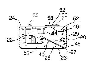
FIG. 3 is a front elevational view, partly in section, of the deflectable
isolation barrier of FIG. 2 installed in a box shallower than that of FIG. 2;
FIG. 4 is a top plan view of the access door of the wall plate of FIG.
l;
FIG. 5 shows the device illustrated in FIG. 2 with conductors placed
in the two shown compartments;
3

CA 02280056 1999-08-10
FIG. 6 is a top plan view of a modified wall plate of FIG. 1;
FIG. 7 is a top plan view of the deflectable isolation barrier of FIGS.
2 and 3;
FIG. 8 is front perspective view of a further embodiment of a
deflectable isolation barrier constructed in accordance with the concepts of
the
invention.
FIG. 9 is a top plan view of the device of FIG. 8;
FIG. 10 is a front elevational view, partly in section, of the device of
FIG. 9, taken along the lines 10-10.
FIG. 11 is a front elevational view, partly in section of the device of
FIG. 10, installed in and to a standard device box.
DESCRIPTION OF THE PREFERRED EMBODIMENTS
The National Electrical Code (N.E.C.) has strict requirements for
separation of line voltage power conductors (120V, 220V) from signal current
conductors (24 Volt or less, telephone and computer lines). The signal lines
must
be physically separated from higher voltage power conductors to prevent
accidental contact between them when installing or servicing the power line or
signal conductors. The separation of high and low voltage conductors within
the
same box is intended for use with such things as line voltage electronic
devices
that require low voltage input signals to them for control purposes.
4

CA 02280056 1999-08-10
The line voltage electronic devices and control devices are often
installed in a standard device box or so-called "4 inch box" which actually
measures 411/16 x 41'/,6. These boxes have provision to be mounted to a stud,
rafter
or other suitable support and mounting ears to which various devices can be
attached and then covered by a wall plate. The boxes have a base member or
wall
and four side walls fixed to the base member to form a box open at the top
surface
and closed by means of a wall plate and are commonly used for two side by side
devices or a device and its wiring. Knock-outs located in the box walls and
base
member permit power and signal conductors to enter and exit the box.
Turning now to FIGS. 1 to 7 there is shown a 4 inch box or a
standard device box 20 which has mounted therein a line voltage electronic
device
22 mounted to a wall plate 24. The electronic device 22 or other device, such
as a
receptacle, could also project through and beyond the wall plate 26. In such
case
an aperture 28 in wall plate 26, as shown in FIG. 6 would be used. The
aperture
-- will be configured to the portion of the device projecting from the box 20:
The
wall plate 24 is mounted to the mounting ears (not shown) of box 20 by four
mounting screws 30.
A first embodiment of interior chamber divider 40 is shown in FIGS.
2, 3, 5 and 7. A deflectable isolation barrier 42 is mounted to a vertical
support
means 44 which in turn is connected to tabs 46 adjacent the ends of the
vertical
support means 44. These tabs 46 may be glued, soldered, welded, brazed, bonded

CA 02280056 1999-08-10
t
or the like to the inside surface of wall plate 24. The barrier 42 and the
support
means 44 extend for the entire distance between a front wall and its parallel,
spaced apart rear wall so as to divide the standard device box 20 chamber into
two
compartments 50 and 52. Compartment 50 receives the electronic device 22 and
the high voltage power conductors 54 through a suitable knock-out (see FIG. 5)
while compartment 52 receives the low power signal conductors 56 through a
suitable knock-out. To permit access to compartment 52 from the front of box
20
a small access door 58 is provided in the wall plate 24 adjacent compartment
52.
Access door 58, as shown in FIG. 4 is generally rectangular and has a mounting
hole 60 at its top end to be fastened by a screw 62 to the wall plate 24. The
bottom end of access door 58 is notched at 64 and an L-shaped lip 66 is
created to
engage the rear surface of the wall plate 24 when the access door 58 is in
place.
To position the access door 58, the lip is made to engage the rear surface of
wall
plate 24 and the top end is rotated to align hole 60 with a corresponding
aperture
in the wall plate 24 (not shown) at which time screw 62 is employed to
assemble
the access door 58 to wall plate 24.
The deflectability of the deflectable isolation barrier 42 is a definite
advantage when used with standard device boxes of different depths. The box 20
of FIGS. 2 and 5 is 2'/g inches deep and the barrier 42 takes on a steep slope
while
the free end 48 engages the inner surface 25 of base member 23 close to the
curved
edge 27 between the base member 23 and side 29. When the interior chamber
6

CA 02280056 1999-08-10
t
divider 40 is placed in a box 70 having a depth of 1'/2 inches, the barrier 42
takes
on a less steep slope and the free end 48 takes a similar position. Conductors
are
introduced into the compartments 50', 52' through knock-outs.
The interior chamber divider 40 may be made as a single unit and
molded of a thermoplastic or thermosetting plastic, natural or synthetic
rubber or
the like.
It is also possible to form an interior chamber divider 80 with a
deflectable isolation barrier 82 coupled to one wall of a box insert 84 whose
wall
86 provides the support means for barrier 82. Barrier 82 ends in a free end
88.
The insert 84 has a wall 90 parallel with and spaced apart from side wall 86.
Two
short mounting collars 92 permit box insert 84 to be mounted to the box 20 by
means of fasteners 94 which extend through the mounting collars 92 and into
mounting ears 96 on the inside of box 20 (see FIG. 11). The deflectable
isolation
barrier 82 takes a position determined largely by the extent to which box
insert 84
extends into box 20. As shown the free end 88 of barrier 82 engages the
interior
surface 25 of base member 23 and creates two compartments 98 and 100.
While there have been shown and described and pointed out the
fundamental novel features of the invention as applied to the preferred
embodiment, as are presently contemplated for carrying them out, it will be
understood that various omissions and substitutions and changes of the form
and
7

CA 02280056 1999-08-10
t
details of the devices illustrated and in their operation may be made by those
skilled in the art, without departing from the spirit of the invention.
8

Dessin représentatif
Une figure unique qui représente un dessin illustrant l'invention.
États administratifs

2024-08-01 : Dans le cadre de la transition vers les Brevets de nouvelle génération (BNG), la base de données sur les brevets canadiens (BDBC) contient désormais un Historique d'événement plus détaillé, qui reproduit le Journal des événements de notre nouvelle solution interne.

Veuillez noter que les événements débutant par « Inactive : » se réfèrent à des événements qui ne sont plus utilisés dans notre nouvelle solution interne.

Pour une meilleure compréhension de l'état de la demande ou brevet qui figure sur cette page, la rubrique Mise en garde , et les descriptions de Brevet , Historique d'événement , Taxes périodiques et Historique des paiements devraient être consultées.

Historique d'événement

Description Date
Demande non rétablie avant l'échéance 2006-08-10
Le délai pour l'annulation est expiré 2006-08-10
Réputée abandonnée - omission de répondre à un avis sur les taxes pour le maintien en état 2005-08-10
Modification reçue - modification volontaire 2005-02-02
Lettre envoyée 2004-08-20
Toutes les exigences pour l'examen - jugée conforme 2004-07-28
Requête d'examen reçue 2004-07-28
Exigences pour une requête d'examen - jugée conforme 2004-07-28
Demande publiée (accessible au public) 2000-02-19
Inactive : Page couverture publiée 2000-02-18
Inactive : CIB en 1re position 1999-10-06
Inactive : Certificat de dépôt - Sans RE (Anglais) 1999-09-13
Lettre envoyée 1999-09-13
Demande reçue - nationale ordinaire 1999-09-11

Historique d'abandonnement

Date d'abandonnement Raison Date de rétablissement
2005-08-10

Taxes périodiques

Le dernier paiement a été reçu le 2004-07-27

Avis : Si le paiement en totalité n'a pas été reçu au plus tard à la date indiquée, une taxe supplémentaire peut être imposée, soit une des taxes suivantes :

  • taxe de rétablissement ;
  • taxe pour paiement en souffrance ; ou
  • taxe additionnelle pour le renversement d'une péremption réputée.

Les taxes sur les brevets sont ajustées au 1er janvier de chaque année. Les montants ci-dessus sont les montants actuels s'ils sont reçus au plus tard le 31 décembre de l'année en cours.
Veuillez vous référer à la page web des taxes sur les brevets de l'OPIC pour voir tous les montants actuels des taxes.

Historique des taxes

Type de taxes Anniversaire Échéance Date payée
Taxe pour le dépôt - générale 1999-08-10
Enregistrement d'un document 1999-08-10
TM (demande, 2e anniv.) - générale 02 2001-08-10 2001-08-10
TM (demande, 3e anniv.) - générale 03 2002-08-12 2002-06-28
TM (demande, 4e anniv.) - générale 04 2003-08-11 2003-06-04
TM (demande, 5e anniv.) - générale 05 2004-08-10 2004-07-27
Requête d'examen - générale 2004-07-28
Titulaires au dossier

Les titulaires actuels et antérieures au dossier sont affichés en ordre alphabétique.

Titulaires actuels au dossier
LEVITON MANUFACTURING CO., INC.
Titulaires antérieures au dossier
DANILO F. ESTANISLAO
JOSEPH G. JUSTINIANO
SELIN TANSI-GLICKMAN
STEPHEN STEWART
Les propriétaires antérieurs qui ne figurent pas dans la liste des « Propriétaires au dossier » apparaîtront dans d'autres documents au dossier.
Documents

Pour visionner les fichiers sélectionnés, entrer le code reCAPTCHA :


Pour visualiser une image, cliquer sur un lien dans la colonne description du document. Pour télécharger l'image (les images), cliquer l'une ou plusieurs cases à cocher dans la première colonne et ensuite cliquer sur le bouton "Télécharger sélection en format PDF (archive Zip)" ou le bouton "Télécharger sélection (en un fichier PDF fusionné)".

Liste des documents de brevet publiés et non publiés sur la BDBC .

Si vous avez des difficultés à accéder au contenu, veuillez communiquer avec le Centre de services à la clientèle au 1-866-997-1936, ou envoyer un courriel au Centre de service à la clientèle de l'OPIC.


Description du
Document 
Date
(aaaa-mm-jj) 
Nombre de pages   Taille de l'image (Ko) 
Dessin représentatif 2000-02-03 1 7
Description 1999-08-09 8 263
Abrégé 1999-08-09 1 19
Revendications 1999-08-09 3 92
Dessins 1999-08-09 4 98
Courtoisie - Certificat d'enregistrement (document(s) connexe(s)) 1999-09-12 1 140
Certificat de dépôt (anglais) 1999-09-12 1 175
Rappel de taxe de maintien due 2001-04-10 1 111
Rappel - requête d'examen 2004-04-13 1 116
Accusé de réception de la requête d'examen 2004-08-19 1 177
Courtoisie - Lettre d'abandon (taxe de maintien en état) 2005-10-04 1 176
Taxes 2003-06-03 1 30
Taxes 2001-08-09 1 32
Taxes 2002-06-27 1 33
Taxes 2004-07-26 1 37