Note : Les descriptions sont présentées dans la langue officielle dans laquelle elles ont été soumises.
CA 02284408 1999-09-30
Hoover Case 2506 Patent Application
CYCLONIC DIRT CUP ASSEMBLY
BACKGROUND OF THE INVENTION
Technical Field
The invention relates to vacuum cleaners. Particularly, the
invention relates to cyclonic separators for vacuum cleaners. Even more
particularly, the invention relates to a cyclonic dirt cup assembly having a
generally conical truncated cone which directs a dirt-laden airstream in a
cyclonic manner within a dirt cup to separate dirt particles from a stream of
dirt-laden air.
Background Information
It is well known in the art of vacuum cleaners to use cyclonic action
to separate particles from a stream of air. Typically, in these vacuum
cleaners, a stream of dirt-laden air is directed tangentially into a container
or
dirt cup either within or around the outside of a generally cone-shaped
member. The tangential input of the dirt-laden air creates a cyclonic action
within the dirt cup which is maintained by the cone-shaped member. The
cyclonic action within the dirt cup allows the larger dirt particles to fall
from
the airstream due to the force of gravity. Because many of the smaller dirt
particles are not filtered from the airstream by the cyclonic action, vacuum
cleaners having cyclonic separators will typically include a final filter,
such as
1
CA 02284408 1999-09-30
a filter bag or filter cassette, to filter these smaller dirt particles from
the dirt-
laden airstream before the airstream is exhausted into the atmosphere.
Although these prior art vacuum cleaners using cyclonic action
within a dirt cup to separate dirt particles from an airstream are adequate
for
the purpose for which they are intended, it may be inconvenient or
undesirable to input the dirt-laden airstream into the cyclonic separator
tangentially. Additionally, even those vacuum cleaners which do input the air
tangentially may not create a sufficient cyclonic action within the dirt cup
to
adequately separate the dirt particles from the dirt-laden air stream.
Further,
herertofore, many manipulatable vacuum cleaners having cyclonic
separators have been relatively expensive and have required rather intricate
elaborate ducting arrangements to create the cyclonic action.
Therefore, the need exists for a cyclonic dirt cup assembly which
is inexpensive, which allows the dirt-laden airstream to be input into the
dirt
cup at various angles, and which creates and maintains sufficient cyclonic
action within the dirt cup to provide adequate dirt and air separation.
SUMMARY OF THE INVENTION
Objectives of the invention include providing an improved cyclonic
dirt cup assembly which is capable of receiving a stream of dirt-laden air
input into the dirt cup at various angles, and which directs the input dirt-
laden
airstream tangentially within the dirt cup to create a cyclonic action
therein.
A further objective is to provide such a cyclonic dirt cup assembly
2
CA 02284408 2003-07-07
61935-154
which is inexpensive s.nd which i.s capable of creating the
cyclonic action using a simple input ducting arrangement.
Another objective is t.o provide such a cyclonic
dirt cup assembly in which the dirt cup may be easily
~~ removed from the vacuum clearer for emptying of the contents
thereof, and in which the cone rnay be separated from a
support member to allow filter access for cleaning of the
filter.
A further obje~~tive is t.o ;provide such a cyclonic
dirt cup assembly which sustains performance of the vacuum
cleaner by filtering the larger particles from the dirt-
laden airstream using r~yclonic ~~ct.io:n arud fi l.tex-ing the
smaller particles from the airstream using a filter.
A still further objective .is to provide a cyclonic
dirt cup assembly which is of simple construction and which
achieves the stated ob~ject~i.ves in a simple, effective and
inexpensive manner.
These and other objectives will be readily
apparent from the foll.~awing descript:ion taken in conjunction
with t:he accompanying <:~.r;rwings.
In carrying <::>ut~ the invention in one form thereof,
these objectives and advantages are obtained by providing a
cyclonic dirt cup assembly for a vacuum cleaner, said
cyclonic dirt cup assemb:Ly including: a container formed
with an inlet opening for receiving a stream of dirt-laden
air; an inverted truncated cone positioned within the
container and being farmed with a wall, said wall having an
outer surface; and a b<~ffle extending outwardly from the
outer surface of the wa_L7_ of the cone, said baffle being
positioned adjacent to the inlet Operllrlg of the :~:ontainE:r
3
CA 02284408 2003-07-07
61935-154
and cooperating with said cone for directing the stream of
dirt-laden air in a cyc;lonic manner about said outer surface
of the wall of the wall. of the None .
According tca another broad aspect c>f the
invention, there is provided a cyclonic dirt cup assembly
for a vacuum cleaner, said cyclonic dirt cup assembly
including: a container foamed with an inlet opening for
receiving a ~;tream of air; a frmme member rernovably mounted
within the container; a filter <attached to the =rame member,
said filter being forrraed of an <~ir permeable material for
filtering the stream of air as said stream of air passes
through said filter; and a cone positioned within the
container and. pivotally attached to the frame member, said
cone being pivotable away from said frame member to provide
1~> access to the filter for cleaning thereof.
3a
CA 02284408 1999-09-30
BRIEF DESCRIPTION OF THE DRAWINGS
The preferred embodiment of the invention, illustrative of the best
mode in which applicants have contemplated applying the principals is set
forth in the following description and is shown in the drawings and is
particularly and distinctly pointed out and set forth in the appended claims.
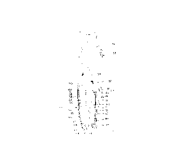
Fig. 1 is a perspective view showing the cyclonic dirt cup assembly
of the present invention in one form thereof attached to a light-weight stick
vacuum cleaner;
Fig. 2 is a side elevational view of the cyclonic dirt cup assembly
of Fig. 1 with a portion of the light-weight stick vacuum cleaner shown in dot-
dash lines;
Fig. 3 is a side elevational view of the cyclonic dirt cup assembly
of Fig. 2 showing the pivotal movement of the cone relative to the supporting
frame member;
Fig. 4 is a perspective view of the cone of the cyclonic dirt cup
assembly of Fig. 3;
Fig. 5 is a rear elevational view of the cone of Fig. 4;
Fig. 6 is a side elevational view of the cone of Fig. 5; and
Fig. 7 is a rear elevational view of the cyclonic dirt cup assembly.
Similar numerals refer to similar parts throughout the drawings.
DESCRIPTION OF THE PREFERRED EMBODIMENT
A light-weight stick vacuum cleaner of one type is shown in Fig. 1
4
CA 02284408 1999-09-30
and is indicated generally at 10. Vacuum cleaner 10 includes a foot or
nozzle 12 and an upper handle 14. Foot 12 has a front portion 16 formed
with a bottom nozzle opening (not shown) for receiving a stream of dirt-laden
air, a raised central portion 18 which forms a dirt duct for conveying the
dirt-
laden air to upper handle 14, and a rear wheel assembly 20 having a pair of
wheels 22 which allow vacuum cleaner 10 to be easily manipulated across
a floor surface to be cleaned. A brush adjustment switch 24 is formed on
front portion 16 which controls a brush strip (not shown) on the bottom of the
foot allowing the brush strip to be placed in either a floor engaging or a
floating position.
Upper handle 14 is connected to foot 12 by a suction tube 26
pivotally mounted to rear wheel assembly 20 and fluidly communicating with
the duct formed by raised central portion 18 and the nozzle opening (not
shown). Upper handle 14 includes a cyclonic dirt cup assembly of the
present invention in one form, indicated at 30, which receives and filters the
dirt-laden air as it exits from suction tube 26 and before it enters a motor-
fan
housing 32 which houses a motor-fan assembly 34 (shown in dot-dash lines
in Fig. 2). Upper handle 14 further includes an upper hand grip portion 36
and may also include an attachment hose 38 (Fig. 1 ) which allows vacuum
cleaner 10 to be converted between "on-the-floor cleaning" and "above-the-
floor cleaning" modes. Top and bottom hooks 40 and 42, respectively, are
positioned on the rear of upper handle 14 and function as a cord wrap to
allow the electrical cord of vacuum cleaner 10 to be easily stored when
5
CA 02284408 2003-07-07
61935-154
vacuum cleaner 10 is not in use.
In the illustrated preferred form of the present invention, cyclonic
dirt cup assembly 30 releasably mounts on upper handle 14 (Fig. 2) and
includes a dirt cup or dirt receiving container 50 and a cyclonic filter
assembly
52. Dirt cup 50 includes a bottom wall 54 and a curved waN 56 extending
upwardly from bottom wall 54. Wall 56 is tapered inwardly from the top to the
bottom thereof and includes a front 58, a rear 60 and a pair of opposed sides
62. A latch 64 is pivotally mounted to the outer surface of bottom wall 54 to
releasably retain dirt cup 50 on upper handle 14. Latch 64 includes a front
handle portion 66, a rear barbed portion 68 and pivots about a pivot point 70,
whereby an upward pressure applied to handle 66 releases barbed portion
68 from its engagement with a catch 72 formed on upper handle 14 of
vacuum cleaner 10. latch 64 is spring biased to the position of Fig. 2
allowing dirt cup 50 to be easily placed and retained on upper handle 14.
Latch 64 is further described in U.S. Patent No. 5,659,922 assigned to the
assignee of the present invention.
Pear 60 of dirt cup 50 is formed with a longitudinally extending
recess 75 (Figs. 2 and 7) which receives suction tube 26 when dirt cup 50 is
attached to upper handle 14, and which forms a flat vertically extending
recessed wall 76. An inlet opening 80 to the dirt cup is formed in recessed
wall 76 thereof which communicates with an outlet opening 82 (Fig. 2)
formed in suction tube 26. A gasket or seal 84 is positioned between
recessed wall 76 and suction tube 26 to seal the fluid connection between
6
CA 02284408 2003-07-07
61935-154
outlet opening 82 and inlet opening 80.
Bottom wall 54 and wall 56 form a dirt-collecting chamber 88 within
dirt cup 50 which collects the dirt and debris filtered from the dirt-laden
airstream by cyclonic filter assembly 52, as described hereinbelow. Dirt-
collecting chamber 88 also functions as a cyclone chamber, wherein the
cyclonic action created by cyclonic filter assembly 52 acts to filter dirt,
dust
and debris from the dirt-laden airstream. Dirt cup 50 is formed with an open
top 90 which receives filter assembly 52, and which allows wall 56 to overlap
an inwardly stepped portion 92 of motor-fan housing 32 to form an labyrinth
seat therewith.
In the preferred embodiment of the present invention, cyclonic filter
assembly 52 includes an inverted truncated cone 100 (Figs. 3 and 7)
pivotally connected to a support frame member 102, and a filter bag 104
which extends upwardly from support frame member 102 in a direction
opposite that of cone 100. Cyclonic ~Iter assembly 52 may include a mesh
screen, filter cartridge or other suitable filter rather than filter bag 104,
or may
be free of an additional filtering element without affecting the concept of
the
invention. Cone 100 is generally elliptical in cross section and is formE:d
with
a front wall 105, a pair of side walls 106 and a rear wall 107. Walls 105-107
form an outwardly extending top lip 108 on cone 100. Lip 108 is formed
with a pair of front notches 110 (Fig. 4) which provide sufficient flexibility
to
lip 108 to allow lip 108 to pivot over a front bottom edge 109 of frame
member 102 (Fig. 3), as described below. Alternatively, cone 100, and thus
7
CA 02284408 1999-09-30
lip 108, may be formed of a material which provides sufficient flexibility to
lip
108 to allow lip 108 to flex over front bottom edge 109 when cone 100 is
pivoted to the assembled position of Fig. 2.
A tab 112 extends upwardly from cone 100 and provides an
attachment surface to allow cone 100 to be stapled, glued, sewn or otherwise
attached to frame member 102. Alternatively, tab 112 could be formed
integrally with supporting frame member 102 allowing frame member 102
and cone 100 to be formed as a one-piece member. A living hinge 114 is
formed between tab 112 and the top edge of lip 108 to allow cone 100 to
pivot in the direction of arrow A (Fig. 3). Living hinge 114 allows cone 100
to pivot between the assembled, dirt collecting position of Fig. 2 and the
pivoted dirt emptying position of Fig. 3.
Walls 105-107 taper inwardly from top to bottom and form a
generally elliptical or oval-shaped bottom opening 116 and a generally
elliptical or oval-shaped top opening 118 which is larger in circumference
than bottom opening 116. Tapered walls 105-107 forms a downwardly
angled surface which acts to direct the incoming dirt-laden airstream in a
downward direction and assists in maintaining the cyclonic action within
chamber 88.
In accordance with one preferred form of the present invention, an
air-directing baffle 120 (Figs. 4-6) is provided which extends outwardly from
rear wall 107 of cone 100. Baffle 120 cooperates with rear wall 107 for
directing the input stream of dirt-laden air in a cyclonic manner. Baffle 120
8
CA 02284408 1999-09-30
also functions as an airflow impediment which impedes a portion of the
cyclonically flowing airstream and assists in separating the dirt particles
from
the dirt-laden airstream, as described herein below.
In the illustrated preferred embodiment, baffle 120 is formed
integrally on rear wall 107 and includes a horizontally extending top wall 122
having an outer end 122A (Figs. 4 and 5), a slightly angled vertical side wall
124, and a generally horizontally extending bottom wall 126 which is
connected to side wall 124 by a radiused corner 128 and which has an outer
end 126A. Top wall 122, side wall 124 and bottom wall 126 terminate in a
common vertical plane B (Fig. 6) and abut the inner surface of vertically
extending recessed wall 76 to substantially seal baffle 120 against wall 76.
Walls 122, 124, 126 of baffle 120 are positioned about inlet opening 80
whereby the baffle walls, recessed wall 76 and rear wall 107 of cone 100,
form an air directing compartment 129 which surrounds or encloses inlet
opening 80 (Fig. 7) and receives the dirt-laden air input into dirt cup 50
through inlet opening 80. A horizontal airflow exit opening 130 is formed
between outer ends 122A and 126A of top wall 122 and bottom wall 126,
respectively, which provides a tangential opening for the dirt-laden air to
exit
air directing compartment 129 and begins the cyclonic action within chamber
88.
Supporting frame member 102 is generally complementary in
shape to open top 90 of dirt cup 50 and is received therein whereby the outer
surface of frame member 102 abuts the inner surface of dirt cup 50 in a
9
CA 02284408 1999-09-30
substantially sealing engagement. By substantially sealing the contact
between frame member 102 and dirt cup 50, the cyclonically filtered
airstream exiting chamber 88 via opening 118 is directed upwardly through
a central opening (not shown) formed in frame member 102. Supporting
frame member 102 is formed with a plurality of notches 132 along the bottom
edge thereof which receive corresponding support flanges 134 formed on the
inner surface of dirt cup 50 to suspend frame member 102 within chamber
88.
Filter bag 104 is attached to the perimeter of the central opening
of frame member 102 and extends upwardly toward motor-fan assembly 34.
Filter bag 104 receives the cyclonically filtered airstream flowing upwardly
through the interior of cone 100 and exiting cone 100 through top opening
118 thereof, and though the opening of frame member 102 to further filter
the airstream before the airstream enters motor-fan assembly 34.
Referring to Figs 1 and 2 in operation, motor-fan assembly 34
creates a suction in the bottom opening of foot 12 which picks up dirt, dust
and debris from a floor surface being cleaned and which produces a dirt-
laden airstream. The dirt-laden airstream flows through the dirt duct formed
by raised central portion 18 of foot 12, through suction tube 26 and out
suction tube outlet 82. As the dirt-laden airstream exits suction tube 26
through outlet 82, the airstream enters dirt cup 50 through inlet opening 80
and in a generally radial or perpendicular direction relative to cone 100. The
dirt-laden airstream contacts downwardly angled rear wall 107 of cone 100
CA 02284408 1999-09-30
producing a downward component to the airstream. A portion of the air flow
will contact and travel downwardly along baffle side wall 124 whereby
radiused corner 128 creates a smooth transition of the airstream between the
vertical direction created by rearwall 107 and the horizontal direction
created
by bottom wall 126 of baffle 120. As the airstream flows along bottom wall
126 it is directed out of air directing compartment 129 through airflow exit
opening 130 in a generally tangential direction relative to cone 100, thus
creating a cyclonic action within chamber 88. This tangential airstream
flowing along bottom wall 126 will also produce a horizontal component to
the remaining portion of the airstream flowing downwardly along tapered rear
wall 107 of cone 100.
This tangentially directed airstream creates a cyclonic action within
chamber 88 which allows larger dirt particles contained in the cyclonic
airstream to fall therefrom due to the force of gravity. Further, as a portion
of the airstream flows within the upper section of dirt cup 50, the airstream
will eventually flow into the rear surface of baffle side wall 124 causing the
dirt particles carried by the airstream to hit baffle side wall 124 losing
their
horizontal velocity. The force of gravity will pull the dirt particles to the
bottom of dirt cup 50 where the dirt particles will collect until dirt cup 50
is
emptied.
The remaining portion of the airstream will continue to flow in a
circular direction about the lower section of dirt cup 50. As this remaining
portion of the airstream reaches the bottom of chamber 88, the air flow will
11
CA 02284408 2003-07-07
61935-154
be drawn upwardly through bottom opening 116 and top opening 118 of cone
100, and through the opening formed in frame member 102 before flowing
into filter bag 52. Filter bag 52 further filters the smaller dirt particles
from the
airstream and emits a clean filtered airstream to motor-fan assembly 34. The
clean filtered air flows through motor-fan assembly 34 and is emitted to the
atmosphere. By filtering the larger dirt particles from the airstream prior to
the airstream flowing into the filter bag, performance of the vacuum cleaner
is sustained as the larger particles will not flow into and clog the filter
bag.
It is understood that although the stream of dirt-laden air is shown
in Figs. 2 and 7 being input into chamber 88 in a radial direction, the stream
of dirt-laden air may be input into chamber 88 at various other angles with
baffle 120 directing the airstream tangentially to create the cycionic action
within chamber 88. For example, the airstream may be input tangentially.
In such a tangentially input arrangement, baffle 120 assists in creating the
cyclonic action by blocking or shielding the top, bottom and one side of input
opening 80 to prevent the cyclonically flowing air within chamber 88 from
affecting the incoming airstream. The airstream may also be input into
chamber 88 at a vertical angle wherein the airstream will contact either top
wall 122 or bottom wall 126 before being directed tangentially out airflow
exit
opening 130.
Accordingly, cone 100 and baffle 120 create and maintain a
cyclonic.action within chamber 88 from a stream of dirt-laden air which may
be input into chamber 88 at various angles. This cyclonic action filters
larger
12
CA 02284408 1999-09-30
dirt particles from the dirt-laden airstream with filter bag 52 filtering the
smaller dirt particles from the dirt-laden airstream. Dirt cup 50 may be
easily
removed from its attachment to upper handle 14 by pivoting latch 64 and
applying an outward and downward force on dirt cup 50. Cyclonic filter
assembly 52 including cone 100, frame member 102 and filter bag 104, may
be lifted from its placement within dirt cup 50 allowing the dust and dirt
collected in chamber 88 to be easily emptied from dirt cup 50. Cone 100
maybe pivoted about living hinge 114 allowing any dirt or debris to be
emptied from filter bag 104. Cone 100 may be pivoted back to the
assembled position on frame member 102 with notches 110 providing
sufficient flexibility to allow lip 108 to clear the front bottom edge 109 of
frame
member 102. As cyclonic filter assembly 52 is placed back into dir cup 50,
bottom wall 126 of baffle 120 may cam against the inner surface of recessed
wall 76 thus maintaining both the engagement between lip 108 and frame
member 102 and the engagement between baffle 120 and recessed wall 76.
Notches 132 formed in frame member 102 rest against support flanges 134
to suspend cyclonic filter assembly 52 within chamber 88.
Accordingly, the improved cyclonic dirt cup assembly is simplified,
provides an effective, inexpensive, and efficient device which achieves all of
the enumerated objectives. While there has been shown and described
herein a preferred embodiment of the present invention, it should be readily
apparent to persons skilled in the art that numerous modifications may be
made therein without departing from the true spirit and scope of the
13
CA 02284408 1999-09-30
invention. Accordingly, it is intended by the appended claims to cover all
modifications which come within the spirit and scope of the invention.
14