Note : Les descriptions sont présentées dans la langue officielle dans laquelle elles ont été soumises.
CA 02284610 2003-O1-30
21421-301
_ 1 ._
VEHICLE
This invention relates to a :railway vehicle with
vehicle parts including a czar body and an undercarriage,
whereby the car body is supported. on are undercarriage frame
of a truck by means of at Least c,ne int:erposed connecting
device, and the connecting devit::e comprises an actuator that
has two actuator elements that can be adjusted with respect
to one another axially only in a.~ straight: line, a one of
which is connected with the truck framed and an other of
which is connected with the car body.
On a similar railway vehicle of the prior art:
(DE 42 34 553 Al), between a car body and a truck located
underneath it there is a cc~nnecting device that has a
hydraulic actuator with a piston and a cylinder housing as
an adjustment means that can be adjusted axially only in a
straight line in relation to one another. The cylinder
housing and the piston or the p:i.ston roc: connected to t:he
piston are each provided with a sing:ie-~:~x~s knuckle joint,
whereby one knuckle joint :is coupled with the car body and
the other knuckle joint is coupled in an at least a largely
perpendicular orientation u.nderr~.eath it to the undercarriage
frame of the trucl~:. They actuator .is thereby used to control
the level of the ear body. One d:isadvarrtage of this design
is that in the event of a fai:Lure of a hydraulic and/or
pneumatic system, special support elemer-its must be provided,
which completely relieve the ~act:.uators whiclu are .fastened
flexibly on both ends, because without additional support
means, these actuators can tip around t:rne knuckle connector,
as a result of which there cam be an unacceptable
displacement of the car body tait::h respect to the
undercarriage.
CA 02284610 2003-O1-30
21421-301
1a-
An aspect of the invention, c;n ~a vehicle of 1=he
type described above is to take measure's so that the
connecting means also perform the necessary support function
even in the event of malfunctions car fai7~ures of other
systems.
The invention teaches a railway vehicle with
vehicle parts including a cvar body and an undercarriage,
whereby the car body is supported on are undercarriage frame
cf a truck by means of at least one .int.erposed connecting
device, and the connecting device comprises an actuator that
has two actuator elements that c:an be adjusted with re~apect
to one another axially only in a straight line, a one of
which is connected with the truck frame and an other of.
which is connected with the car body, c~~haracterized by the
fact that in the connecting device, one of: the actuator-
elements of the actuator is connected r~:Lgi.dly and the other
actuator element is connected so that it: can execute both
pivoting and transverse movements with the respective
associated other vehicle part ox:~ one of th.e actuator
elements of the actuator can be moved to a. limited extent
only at a right angle to its -~ck.:uator axis, and the other
actuator element i..s conn.ected wz.t:h the ~:~espective other
vehicle part so that it can move in a pivoti..ng manner.
In one configuration caf a vehicle as claimed by
the invention, a connecting dPVice forms a support
mechanism, on which the actuator ~~an always be kept in a
perpendicular
CA 02284610 1999-09-21
-2- 3181-990924
orientation with respect to one of the two vehicle parts. Rotational and
displacement
movements between the horizontal plane formed by the truck frame and the plane
formed by
the underside of the car body, on the other hand, are equalized by knuckle
connectors
having the characteristic of a ball-and-socket joint and sliding connectors.
The sliding
connectors for each connecting device thereby have degrees of freedom in
translation only
in a plane that runs parallel to the plane to which the connecting element or
elements are
fastened. The connecting devices thereby stand perpendicular to the plane on
which they
are fastened. In the event of the failure of the actuator that is realized in
the form of a
hydraulic cylinder, an electrically driven spindle system or a similar
mechanism, the actuator
can therefore not rotate with respect to the vehicle part to which it is
fastened. Consequently,
in any case, the minimum axial length of the actuator determines the distance
between the
vehicle parts that must be kept at a distance from one another and that can
move within
specified limits with respect to one another. The necessary rotational
movements are
thereby absorbed by the knuckle joint that is integrated into the connecting
device. In this
case, the knuckle connector can be realized in the manner of a universal joint
or a ball-and-
socket joint, while the movement of the sliding connector in translation can
be restricted to
the magnitude necessary for the operation of the railway vehicle by the
attachment of
corresponding stops. The connecting device thus consists of a mechanical-
functional series
arrangement that consists of the actuator, a sliding connector that can be
adjusted only in
one plane and a knuckle connector that is realized in the manner of a ball-and-
socket joint.
This connecting device includes, in the form of the changeable-length
actuator, an element
for the simultaneous limitation of the vertical distance between the
undercarriage and the car
body, and in the form of the restricted-motion sliding connector, a functional
element, the
sole purpose of which is to restrict the movement between the two vehicle
parts in the
direction of the vehicle travel or at a right angle to the direction of
travel. The knuckle
connector also allows only the inclinations or torsion between the planes
described by the
vehicle parts that occur during operation.
When the connecting device that is realized in the form of a support and
interface between
the undercarriage and the car body consists of three components, each of which
makes
possible different degrees of freedom for the movement between the vehicle
parts, movable
elements of two of the components can each be connected rigidly with the two
vehicle parts,
so that the third component always forms the connecting element between the
second
adjustable elements of the fastened components. In all cases, only the
reciprocating
movement of the
CA 02284610 1999-09-21
-3- 3181-990924
respective actuator is available for the vertical adjustment between the
undercarriage and
the car body, and only by a maximum of this reciprocating distance can the car
body
descend toward the undercarriage, because neither the knuckle connector nor
the sliding
connector allows a movement in this direction, and the longitudinal axis of
the actuator
cannot be tipped with respect to one of the vehicle parts.
The invention is explained in greater detail below with reference to the
accompanying
drawings, which contain schematic diagrams of one exemplary embodiment of the
invention.
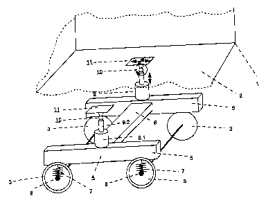
Figure 1 is a schematic diagram in perspective of an undercarriage with
connecting
devices to a car body located above it, and
Figure 2 is a side view of a connecting device.
Figure 1 shows a schematic illustration of a vehicle, in particular or a
railway vehicle, and a
car body 1, underneath the floor wall 2 of which there is at least one truck.
The truck has at
least one axle and two wheels 3, and in this case two axles or four wheels 3.
The wheels 3
are realized in the form of railroad car wheels. An undercarriage frame 4 is
thereby
supported with longitudinal beams 5 that run in the direction of travel of the
truck, which
beams 5 are connected to each other by means of at least one cross member 6,
are
supported by means of primary springs 7 on wheel bearing elements 8 of the
wheels 3, and
thus couple the wheels 3 together so that they run smoothly. Approximately in
the middle of
two wheels 3 that are one behind the other in the direction of travel, on each
longitudinal
beam 5 perpendicular to the plane formed by these longitudinal beams 5, there
is a coupling
element unit, by means of which the car body 1 is supported with its floor
wall 2 on the truck.
The coupling element unit consists of an actuator 9 that acts as a spring
element, a knuckle
joint connector 10 that can be tilted in all directions and a conducting
connector 11 that is
located mechanically in series in the direction of action of the actuator 9.
The actuators 9,
which can be realized in particular in the form of hydraulic cylinders or in
the form of geared
motors, have two actuator elements 9.1 and 9.2 that can be adjusted axially
only in a straight
line with respect to one another. The knuckle joint 10 can be realized in the
form of a
universal
CA 02284610 1999-09-21
-4- 3181-990924
or ball-and-socket joint, in the form of an elastomer joint or in the form of
a spring steel bar,
so that it can execute pivoting movements with a restricted amount of movement
in all
directions. The sliding connector 11 has degrees of freedom in translation
only in a plane
that lies parallel to the floor wall 2 of the car body 1. The displacement
capability in a plane
of this sliding connector, which is not directionally restricted, is thereby
limited to specified
values. As a result of the association between the individual components 9,
10, 11 of the
connecting device, only the actuator can compensate for differences in the
distance between
the truck 4 and the car body 1, the knuckle joint 10 can compensate only for
non-
directionally dependent tipping movements, and the sliding connector 11 can
compensate
only for movements that are directed at right angles to the actuation
direction or to its
actuation axis 12. In this regard, it is basically unimportant in what
sequence the
components 9, 10, 11 are connected to one another, as long as the two
components on the
ends are fastened on one hand to the truck 4 and on the other hand to the car
body 1.
In the exemplary embodiment depicted in the illustration, the cylinder housing
9.1 is fastened
rigidly on one of the longitudinal beams 5, for example by means of hydraulic
actuators 9,
with a perpendicularly oriented actuator axis 12. The other actuator element
9.2 of the
actuator 9 is a tappet rod of the cylinder piston that is guided so that it
can be displaced in a
straight line only along the actuation axis 12, whereby the free end of this
actuator element
9.2 is rigidly connected with the first pivoting element 10.1 of the pivoting
connector 10, while
the second pivoting element 10.2 is rigidly connected to the primary sliding
member 11.1 of
the sliding element 11. The knuckle joint 10 that is realized in the form of a
ball-and-socket
joint allows only tipping movements that occur between the planes formed by
the longitudinal
beams 5 and the floor wall 2. To also be able to compensate for lateral
movements between
the vehicle parts 1, 3, 4 or the lateral adjustment that results from a
distortion of the planes,
there is a sliding connector 11, the primary sliding element 11.1 of which is
firmly connected
with the second pivoting element 10.2 of the knuckle joint 10, and the
secondary sliding
element 11.2 of which is firmly connected with the floor wall 2 of the car
body 1.
In this construction, the actuator 9 can replace flexible elements that act as
a secondary
suspension. For this purpose, the actuator 9 can be realized in particular in
the form of a
hydro-pneumatic operating cylinder, and thus can not only allow a vertical
equalization
between the car body and the truck frame, but can also have spring
characteristics like
those possessed otherwise by coil springs, air springs or similar springs. The
spring
CA 02284610 1999-09-21
-5- 3181-990924
characteristic can thereby be controlled as a function of the specific
requirements. The force
coupling between the car body and the truck for the support of longitudinal
and transverse
forces can conventionally be provided, for example, by means of control arms,
truck center
pins or figure-eight coupling elements or elastic buffer or spring elements.
The connecting device 9, 10, 11 can of course also be installed cambered
between the car
body 1 and the truck 4. In that case, the sliding connector 11 can be also be
installed without
any adverse effect on function and safety, between the respective longitudinal
beam 5 and
the facing actuator element 9.1 of the actuator 9. In that case, the secondary
joint element
10.2 is firmly connected with the car body 1. Without any change in function,
the sliding
connector 11 can of course also be installed between the actuator 9 and the
knuckle joint
10. In all the variant realizations, and under all operating conditions, the
actuator 9 retains its
perpendicular position with respect to the truck 4 to the extent that it is
connected with it
directly on the longitudinal beams 5 or by means of the sliding connector 11.
If the actuator 9
sits directly on the car body 1, of via the sliding connector 11, it retains
its perpendicular
position under all operating conditions with respect to the plane thereby
defined.
A railway vehicle constructed in the manner described above is suitable in
particular for
passenger transportation, and meets the high requirements set for the quality
of the ride. An
efficient transmission path of the inertial forces from the car body to the
truck frames is
thereby achieved and, in the opposite direction, of the active actuator
movements that
improve the quality of the ride from the truck into the car body. This
transmission occurs with
a simultaneous maintenance of the mobility of the truck with respect to the
car body in terms
of galloping, shaking, rocking and turning-out, as well as the preservation of
the stability of
the vertical support in the event of the failure of the active suspension
stage and the failure
of the horizontal centering of the car body. The construction thereby results
in a stable
position of the car body with reference to the truck. The car body is thereby
supported in a
stable fashion on the trucks, regardless of whether the actuator is active or
passive. The
necessary degrees of freedom of the truck with respect to the car body are
thereby also
achieved in the event of galloping, shaking, rocking and turning-out, as well
as in
combinations of these motions. In this construction, the truck with active
hydro-pneumatic
secondary suspension in the form of
CA 02284610 1999-09-21
-6- 3181-990924
the actuator 9 has the same degrees of freedom as a conventional truck without
active
secondary springs. Moreover, in the event of the failure of the active
secondary springs, the
same degrees of freedom are preserved, which makes possible an uncomplicated
safety
concept.