Note : Les descriptions sont présentées dans la langue officielle dans laquelle elles ont été soumises.
CA 02284637 1999-09-24
WO 98/45b29 PCT/SE98100621
1
DIAPHRAGM VALVE
The present invention concerns a diaphragm valve for
controlling a flow of gaseous or liquid fluid and,
particularly, to direct such flow from at least one port of the
valve to at least one other port of the valve.
WO 95/00782, by the present inventor, describes such a
diaphragm valve including a valve housing having a
substantially circular valve chamber, into which opens a
central channel and on each side thereof a first side channel
and a second side channel. Each side channel has an external
connection for fluid and is separated from the central channel
by means of a respective one of two substantially parallel
valve seat means extending like chords across the valve
chamber. Each valve seat means provides a substantially linear
valve seat for an elastic diaphragm. The diaphragm is adapted
to be brought into and away from sealing contact with at least
one of the valve seat means. Two individually operable control
means are adapted both to press a respective linear portion of
the diapghragm against a respective valve seat, thereby to shut
passage of fluid between the central channel and a respective
side channel, and to positively raise a respective portion of
the diaphragm off a respective one of the valve seat, thereby
to open a flow passage between the central channel and the
respective side channel.
This prior art three-way/three-port diaphragm valve proved to
operate extremely well. There was, however, a desire to convert
it to a 4-way/4-port valve, i.e., a valve for mixing three
flows, or, to direct flow from one external connection (inlet
° port) to one or more of three other external connections
(outlet ports).
That was accomplished by a first development of the valve as
initially stated. This first development is described in
WO 97/17558 by the same inventor. In the diaphragm valve
according to the first development, the valve housing is
provided with a second substantially circular valve chamber,
CA 02284637 1999-09-24
WO 98/45629 PCT/SE98/00621
2
into which opens a fourth channel having an external connection
for fluid and which communicates with the central channel
through an opening in the valve housing. A second elastic
diaphragm is provided and is adapted to be brought into and
away from sealing engagement with a third valve seat means
provided in the second valve chamber. A third control means is
arranged both to press the second diaphragm against the third
valve seat means, thereby to shut passage of fluid between the
fourth channel and the central channel, and to release the
diaphragm from its engagement with the third valve seat means,
thereby to open passage of fluid between the fourth channel and
the central channel.
Also this valve has proven to satisfactory fulfil its objects.
Common to the two prior art valves mentioned is a central
channel having direct communication with an associated port.
Consequently, this port becomes involved also in fluid transfer
between the remaining two ports in the valve according to
WO 95/00782 and between any combination of two of the remaining
three ports in the valve according to WO 97/17558.
It is an object of the present invention to provide a diaphragm
valve allowing transfer of fluid between any combination of at
least two of its ports without any other port being involved.
In achieving this, the new diaphragm valve shall comply with
the same extensive sanitary requirements as the prior one, it
shall be simply and reliably operable and have relatively few
movable parts.
In a diaphragm valve of the kinds described above, the valve
seats can be characterized as thresholds or weirs between
adjacent channels and associated ports. Communication between
two ports is established by fluid passage across but one
threshold.
To achieve the object of the present invention, it is proposed
that the central channel be replaced by a central space having
~no direct communication with any port. Fluid passage from a
~ ___ T
CA 02284637 2005-11-09
3
port to the central space must take place across a threshold,
and passage from the central space to any other port must take
place across a further threshold. Thus, all flow across the
valve has to pass the central space.
In accordance with one aspect of the present invention there is
provided a diaphragm valve, including a valve housing having at
least three ports and at least two valve chambers provided in
the valve housing, each valve chamber having at least one first
space communicating with a respective one of said ports and a
second space separated from said first space by a threshold,
and the second space of each valve chamber communicates only
with said second space of others of said at least two valve
chambers such that communication between any two of said at
least two ports can take place only by passing across two
thresholds.
Embodiments of present invention will now be more closely
described, reference being made to the accompanying drawings,
wherein
- Fig. 1 is a top view of a valve housing of a first
embodiment;
- Fig. 2 is a bottom view of the valve housing according to
Fig. 1;
- Fig. 3 is a vertical central section taken along line
III-III in Fig. 1, but at a larger scale;
- Fig. 4 is a vertical central section taken along line
IV-IV in Fig. 1, at the same scale as Fig. 3~
CA 02284637 2005-11-09
3a
- Fig. 5 is a top view of a valve housing of a second
embodiment;
- Fig. 6 is a bottom view of the valve housing according to
Fig. 5;
- Fig. 7 is a vertical central section taken along line
VII-VII in Fig. 5;
- Fig. 8 is a vertical central section taken along line
VIII-VIII in Fig. 5;
- Fig. 9 is a vertical central section taken along line
IX-IX in Fig. 5;
- Fig. 10 is a perspective view of a possible third
embodiment of the present invention having one valve
chamber in each of the four sides of a valve housing
having a square cross section;
- Fig. 11 is a section along line XI-XI of Fig. 10;
- Fig. 12 is a perspective view of a possible forth
embodiment of the present invention having one valve
chamber in each of the six sides of a valve housing
having the cross section of a regular hexagon;
- Fig. 13 is a section along line XIII-XIII of Fig. 12;
- Fig. 14 is a perspective view of a possible fifth
embodiment of the present invention including a valve
housing having two valve chambers in one flat surface;
CA 02284637 1999-09-24
WO 98/45629 PCT/SE98/00621
4
- Fig. 15 is a section along line XV-XV of Fig. 14;
- Fig. 16 is a perspective view of a possible sixth
embodiment of the present invention including a vavle
housing having two valve chambers in each of two opposed
flat surfaces;
- Fig. 17 is a section along line XVII-XVII of Fig. 16;
- Fig. 18 is a perspective view of a seventh embodiment of
the present invention including a valve housing having
two valve chambers in each of two opposed flat surfaces
(as in Figs. 16 and 17) and one valve chamber in each of
two opposed endsurfaces; and
- Fig. 19 is a section along line XIX-XIX of Fig. 18.
Like the membrane valve described in WO 97/17558, the valves
according to the first and second embodiments of the present
invention described with reference to Figs. 1 - 4 and Figs. 5 -
9, respectively, include a valve housing having an upper and a
lower valve chamber, each having valve seat means and an
elastic diaphragm as well as an operating unit capable of
controlling movements of the associated diaphragm so as to
bring it into and away from sealing contact with the respective
valve seat means.
Since is is preferred to utilize operating units as described
in WO 97/17558 with the embodiments of the present invention,
they will not be described herein in detail.
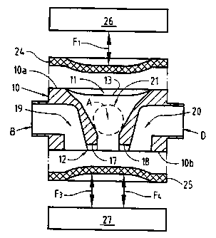
The first embodiment of the present invention described in
Figs. 1 - 5 includes a four port valve housing 10 having an
upper valve chamber 11 and a lower valve chamber 12 provided in
opposite parallel flat surfaces 10a, lOb of the valve housing.
It appears from Figs. 1 and 2 that the valve chambers are
substantially circular in plan view, and from Figs. 3 and 4
that they are substantially bowl or plate shaped in side view.
Extending like parallel chords across the upper valve chamber
11 are two valve seat means in the shape of weirs or thresholds
13 and 14 (Fig. 1). Interiorly provided in the valve housing 10
are well-like channels 15, 16 (see Fig. 4) that open in the
__. __T .._ _ ____ __ _ ____ T
CA 02284637 1999-09-24
WO 98/45629 PCT/SE98/00621
valve chamber 11 radially outside the thresholds 13, 14,
respectively, and communicate with respective ports A and C.
Similarly, the lower valve chamber 12 has two parallel valve
5 seat means in the shape of weirs or thresholds 17, 18 extending
like parallel chords over the valve chamber (Fig. 2).
Interiorly provided in the valve housing 10 are likewise well-
like channels 19, 20 that open in the valve chamber 12 radially
outside the thresholds 17, 18, respectively, and communicate
with respective opposite ports B and D.
As appears from Figs. 1 and 2, the ports A and C are mutually
aligned and diametrically opposed to each other as are the
ports B and D. It also appears that the common axis of the
channels 15 and 16 and their associated ports A and C and the
common axis of the channels 19 and 20 and their associated
ports B and D are perpendicular to each other, and, further,
that the mutually parallel thresholds 13, 14 associated to the
channels 15, 16 are perpendicular to the mutually parallel
thresholds 17, 18 associated to the channels 19, 20.
Between the thresholds 13, 14 of the upper valve chamber 11 is
provided a~substantially v- or funnel-shaped recess or cavity
21 (Fig. 3) tapering from substantially the diameter length of
the valve chamber 11 towards the lower valve seat 12 where it
opens between the thresholds 17 and 18. The width of the cavity
equals the distance between the thresholds 13 and 14.
Correspondingly, between the thresholds 17, 18 of the lower
valve chamber 12 is provided a likewise substantially v- or
funnel-shaped recess or cavity 22 (shown inverted in Fig. 4)
tapering from substantially the full diameter length of the
' valve chamber 12 towards the upper valve seat 11 where it opens
between the thresholds 13 and 14. The width of the cavity 22
' equals the distance between the thresholds 17 and 18.
Together, the cavities 21 and 22 form a central space 23
extending through the valve housing 10 between the valve
chambers 11 and 12 and having no communication with any of the
CA 02284637 1999-09-24
WO 98/45629 PCT/SE98/00621
6
ports A, B, C and D except across a corresponding threshold 13,
14, 17 and 18, respectively.
Shown in Figs. 3 and 4 are an upper diaphragm 24 and a lower
diaphragm 25 adapted for cooperation with the thresholds 13, 14
of the upper valve chamber 11 and with the thresholds 17, 18 of
the lower valve chamber 12, respectively. In order not to
interfere with details of the valve housing, the diaphragms are
shown spaced from the upper surface 10a and the lower surface
10b, respectively, of the valve housing 10. In operation, the
diaphragms are clamped between respective upper and lower
operating units 26, 27 and the upper valve housing surface 10a
and the lower valve housing surface 10b, respectively. Both
operating units schematically shown in Figs. 3 and 4 are
suitably of the first kind described in WO 97/17558 having two
control means selectively movable in the directions indicated
by arrows F1, Fz, F3 and F4 to press one portion each of a
diaphragm 24, 25 against a respective threshold 13, 14 and 17,
18, and to raise corresponding portions off the thresholds.
Now, by choosing different combinations of pressing and raising
diaphragm portions, flow between the different ports may be
established at least as appears from the following table:
Two-way communication between ports
A H B C H B A + H B A H C D H B
C
Fl + Fl F1 + F1 Fl _
- +
Fz - FZ F2 + FZ FZ -
+ +
F3 + F3 F3 + F3 F3 +
+ -
F.~ - F4 F4 - FQ F9 +
- -
In the above table, Fl, F.Z, F3 and F4 refer to the directions of
movement of the control means of the operating units 26, 27,
and a +sign implies a direction of movement to open flow
passage across a threshold by raising a diaphragm portion off
an associated threshold, whereas a -sign implies a direction of
CA 02284637 1999-09-24
WO 98/45629 PCT/SE98/00621
7
movement to shut flow passage across a threshold by pressing a
diaphragm portion against an associated threshold.
The second embodiment of the present invention shown in Figs. 5
- 9 includes a three-port valve housing 30 having an upper
valve chamber 31 and a lower valve chamber 32 provided in
opposite parallel surfaces 30a, 30b of the valve housing. It
appears from Figs. 5 and 6 that the valve chambers are
substantially circular in plan view and substantially bowl or
plate shaped in side view.
Extending like parallel chords across the upper valve chamber
31 are two valve seat means in the shape of weirs or thresholds
33 and 34 (Fig. 5). Interiorly provided in the valve housing 30
are well-like channels 35, 36 (see Figs. 8 and 9) that open in
the valve chamber 31 radially outside the thresholds 33, 34,
respectively, and communicate with respective ports A~ and C'
that are mutually aligned and diametrically opposed to each
other. Evidently, the arrangement of the upper valve chamber 31
with its associated thresholds, channels and ports is similar
to that of the upper valve chamber 11 of the first embodiment.
The lower valve chamber 32 has but one valve seat means in the
shape of a weir or threshold 37, excentrically extending like a
chord over the valve chamber (Fig. 6). Interiorly provided in
the valve housing 30 is a well-like channel 39 that opens in
the valve chamber 32 radially outside the threshold 37 and
communicates with a port D'.
It appears from Fig. 5 and 6 that the common axis of the
channels 35 and 36 and their associated ports A~ and C~ and the
common axis of the channel 39 and its associated port D' are
perpendicular to each other, and, further, that the mutually
parallel thresholds 33, 34 associated to the channels 35, 36
are perpendicular to the threshold 38 associated to the channel
39.
Between the thresholds 33, 34 of the upper valve chamber 31 is
provided a recess or cavity 41 (Figs. 5 and 7) extending
CA 02284637 1999-09-24
WO 98/45629 PCT/SE98100621
8
through the valve housing to open in the lower valve chamber 32
on the opposite side of the threshold 38 relative to the
channel 39. The width of the cavity equals the distance between
the thresholds 33 and 34 (Fig. 5).
Also in the lower valve chamber 32 there is provided, on the
opposite side of the threshold 38 relative to the channel 39, a
recess or cavity 42 (Figs. 6 and 7) extending through the valve
housing to open in the upper valve chamber 31 between the
threholds 33, 34.
Together, the cavities 41 and 42 form a central space 43
extending through the valve housing 10 between the valve
chambers 11 and 12 and having no communication with any of the
ports A', B', C' and D' except across a corresponding threshold
33, 34, 3 and 38, respectively.
Shown in Figs. 7, 8 and 9 are an upper diaphragm 44 and a lower
diaphragm 45 adapted for cooperation with the thresholds 33, 34
of the upper valve chamber 31 and with the threshold 38 of the
lower valve chamber 32, respectively. In order not to interfere
with details of the valve housing, the diaphragms are shown
spaced from the upper surface 30a and the lower surface 30b,
respectively, of the valve housing 30. In operation, the
diaphragms are clamped between respective upper and lower
operating units 46, 47 and the upper valve housing surface 30a
and the lower valve housing surface 30b, respectively. Like in
Figs. 3 and 4, the upper operating unit 46 schematically shown
in Figs. 7 - 9 is suitably of the first kind described in
WO 97/17558 having two control means selectively movable in the
directions indicated by arrows F1, F2 to press one portion each
of a diaphragm 44 against a respective threshold 33, 34,
respectively, and to raise corresponding portions off the
thresholds. The lower operating unit 47 schematically shown in
Figs. 7 - 9 is suitably of the second kind described in
WO 97/17558 having only one control means selectively movable
in the directions indicated by an arrow FS to press a portion
of a diaphragm 45 against the threshold 38 and to raise that
portion off the threshold.
1
CA 02284637 1999-09-24
WO 98/45629 PCT/SE98/00621
9
Now, by choosing different combinations of pressing and raising
diaphragm portions, flow between the different ports may be
established at least as appears from the following table:
Two-wav c~mmmn; gar; r", r,or,.,on~
_ .. __
A' H D' C' H D' A' + C' H D' A' H C'
Fi + Fi _ Fi + F~ +
F2 _ F2 + F2 + Fz +
Fs + Fs + Fs + Fa _
In the above table, Fl, Fz and Fs refer to the directions of
movement of the control means of the operating units 46, 47,
and a +sign implies a direction of movement to open flow
passage across a threshold by raising a diaphragm portion off
an associated threshold, whereas a -sign implies a direction of
movement to shut flow passage across a threshold by pressing a
diaphragm portion against an associated threshold.
In the above description of the first and second embodiment of
the present invention, the two valve chambers are provided in
opposite parallel surfaces of the valve housing. However, the
principles of the present invention involve a high degree of
freedom as to the location of valve chambers. It would be quite
possible, thus, to arrange two or more valve chambers in flat
surfaces of a valve housing that are not opposite to each other
provided only there is a possibilty to provide "a central
space", such as a channel, between them. Consequently, even two
or more valve chambers provided in the very same surface would
be quite possible.
A few examples of such possible arrangements will be briefly
described with reference to Figs. 10 - 19.
In Fig. 10 is shown a perspective view of an embodiment
including a valve housing block 100a having a substantially
square cross section. One valve chamber 101 is provided in each
of the four sides of the square cross section (Fig. 11). Each
CA 02284637 1999-09-24
WO 98/45629 PCT/SE98/00621
valve chamber has thresholds 102, 103 and between the
thresholds a cavity 104 communicating with a corresponding
cavity of each other valve chamber through internal
intersecting channels 105, 106. Channels 107, 108 open in each
5 valve chamber outside the thresholds 102, 103 and communicate
with respective upper and lower ports P1, P2.
Fig. 12 shows a perspective view of an embodiment having one
valve chamber 101 in each of the six sides of a valve housing
10 block 100b having the cross section of a regular hexagon.
Internal, intersecting channels 109, 110, 111 (Fig. 13)
extending between opposed valve chambers connect the cavities
104 of all valve chambers 101. Channels 107, 108 open in each
valve chamber 101 and communicate with respective upper and
lower ports P1, P2.
Figs. 14 and 15 show a valve housing block 100c having two
valve chambers 101 in an upper flat surface. An internal
channel 112 connects the cavities 104 of the two valve
chambers, and ports P1, P2 communicate with a respective valve
chamber as before.
Figs. 16 and 17 show a valve housing block 100d having two
valve chambers 101 in each of two opposed flat surfaces. Three
internal channels 113, 114, 115 interconnect all four valve
chambers, and ports P1, P2, P3, P4 communicate with a
respective valve chamber.
Figs. 18 and 19 show an embodiment having a valve housing block
100e with two valve chambers 101 in each of two opposed flat
surfaces and one valve chamber 101 in each of two opposed end
surfaces. Three internal channels 116, 117, 118 interconnect
all six valves, and ports P1, P2, P3, P4, P5, P6 communicate
with a respective valve chamber.
r ___ ____ - __ _~