Sélection de la langue

Search

Sommaire du brevet 2284693 

Énoncé de désistement de responsabilité concernant l'information provenant de tiers

Une partie des informations de ce site Web a été fournie par des sources externes. Le gouvernement du Canada n'assume aucune responsabilité concernant la précision, l'actualité ou la fiabilité des informations fournies par les sources externes. Les utilisateurs qui désirent employer cette information devraient consulter directement la source des informations. Le contenu fourni par les sources externes n'est pas assujetti aux exigences sur les langues officielles, la protection des renseignements personnels et l'accessibilité.

Disponibilité de l'Abrégé et des Revendications

L'apparition de différences dans le texte et l'image des Revendications et de l'Abrégé dépend du moment auquel le document est publié. Les textes des Revendications et de l'Abrégé sont affichés :

  • lorsque la demande peut être examinée par le public;
  • lorsque le brevet est émis (délivrance).
(12) Demande de brevet: (11) CA 2284693
(54) Titre français: APPAREIL DE LAVAGE COMPRENANT UN CORPS FLOTTANT
(54) Titre anglais: WASHING APPARATUS COMPRISING A FLOAT BODY
Statut: Réputée abandonnée et au-delà du délai pour le rétablissement - en attente de la réponse à l’avis de communication rejetée
Données bibliographiques
Abrégés

Abrégé français

L'invention concerne un appareil de lavage de pâte à papier, comprenant une cuve (2) verticale en forme de colonne, et une unité écran (7). L'unité écran (7) se déplace dans la cuve de lavage, d'une position haute à une position basse à une première vitesse pendant une phase de classage et de la position basse à la position haute à une vitesse nettement plus élevée pendant un mouvement de retour. Un corps flottant (30) exerce une force de flottabilité sur l'unité écran.


Abrégé anglais


In a washing apparatus for washing cellulose pulp, comprising a vertical,
column-shaped washing vessel (2), and a screen unit (7) which is movable in
the washing vessel, during a screening phase, at a first speed, from an upper
position to a lower position, and, during a return movement, at a
substantially higher speed, from the lower position to the upper position,
there is a float body (30) which exerts a buoyancy force on the screen unit.

Revendications

Note : Les revendications sont présentées dans la langue officielle dans laquelle elles ont été soumises.


-7-
CLAIMS
1. Arrangement for a washing apparatus for washing
cellulose pulp, comprising a vertical, column-shaped
washing vessel (2), and a screen unit (7) which is
movable in the washing vessel, during a screening
phase, at a first speed, from an upper position to a
lower position, and, during a return movement, at a
substantially higher speed, from the lower position to
the upper position, characterized in that
it comprises a float body (30) which exerts a buoyancy
force on the screen unit.
2. Arrangement according to Claim 1,
characterized in that the float body (30)
is operational in liquid inside the screen unit.
3. Arrangement according to Claim 2,
characterized in that the float body (30)
is operational in a filtrate consisting of used washing
liquid.
4. Arrangement according to any of Claims 1 - 3,
characterized in that the float body
(30), and thus its buoyancy force on the screen unit
(7), is dimensioned such that the total work in the
form of energy supplied to the system in which the
screen unit is included is minimized in order, during a
working cycle, to move the screen unit and the float
body from the upper position to the lower position and
back to the starting position.
5. Arrangement according to any of Claims 1 - 4,
characterized in that the float body (30)
extends along most of the length of the screen unit
(7).

-8-
6. Arrangement according to Claim 5,
characterized in that the screen unit (7)
surrounds the float body (30), and in that between the
screen unit and the float body there is a circular gap
(31) for filtrate in the form of used washing liquid.
7. Arrangement according to any of Claims 5 and 6,
characterized in that a central pipe (24)
extends from the top part of the arrangement through
the float body to the bottom part of the arrangement.
8. Arrangement according to any of the preceding
claims,
characterized in that the washing vessel
consists of a pressure vessel (2) forming part of a
pressure diffuser (1).
9. Arrangement according to any of the preceding
claims,
characterized in that the displacement of
the screen body (30) amounts to the weight of the
screen unit (7) ~ 75%, preferably ~ 50%, expediently ~
25%, while the width of the gap (31) between the float
body and the screen unit must amount to at least 5% of
the inner radius of the screen unit, preferably 5 - 25%
and expediently 10 - 25% of the radius.
10. Arrangement according to any of the preceding
claims,
characterized in that the displacement of
the float body amounts to at least 1 tonne, preferably
at least 3 tonnes, expediently at least 5 tonnes, and
particularly preferably at least 10 tonnes.

Description

Note : Les descriptions sont présentées dans la langue officielle dans laquelle elles ont été soumises.

CA 02284693 1999-09-23
WO 98/45531 PCT/SE98/00579
Washin~~ apparatus comprising a float body
TECHNICAL FIELD
The invention relates to an arrangement for a
washing apparatus for washing cellulose pulp,
comprising a vertical, column-shaped washing vessel,
and a screen unit which is movable in the washing
vessel, during a screening phase, at a first speed,
from an upper position to a lower position, and, during
a return movement, at a substantially higher speed,
from the lo~rer pc>sition to the upper position. The
invention relates in particular to improvements to
pressure diffusers.
BACKGROUND TO THE INVENTION
In so-called pressure diffuser:; used in the
cellulose pulp industry for washing pulp in
continuously operating washing columns, the screen unit
is given a reciprocating movement with the aid of a
hydraulic working cylinder via a drag bar. The stroke
length is normally up to about one metre. During the
downward working stroke, the screen unit is fed slowly
downwards at a speed which only slightly exceeds the
speed at which the cellulose pulp falls through the
column. By contrast:, the speed on the return stroke is
high: normally about 1 - 1.5 m/sec. The screen unit
which is to be lifted during this rapid return movement
can weigh over ten tonnes, and even bigger
installations have been planned. In addition to this,
there is the friction between the screen unit and the
cellulose pulp in the column. The working cylinder and
other parts of the hydraulic unit must therefore be
given very large dimensions so as to be able, within a
short time, t~u perform considerable work. This entails,
for example, hydraulic- oil flow rates of over 10,000
1/min; oil quantities which additionally have to be
filtered and cooled during the work cycle of the
hydraulic unit. The systems existing at present do not
solve these ~~roblems in a satisfactory manner, a fact
which poses an obstacle to developments within this

CA 02284693 1999-09-23
WO 98/45531 PCT/SE98/00579 '
- 2 -
area of technology towards ever bigger pressure
diffusers and, thus, ever heavier screen units.
It is an object of the invention to remedy the
above problems and offer a solution aimed at lightening
the hydraulic system. It will be appreciated, however,
that although the invention has been developed with the
aim of solving the problems which are acute in the
field of pressure diffusers within the cellulose
industry, it is also possible to envisage the invention
having another area of application.
These and other objects of the invention can be
achieved by the fact that it is characterized by what
is stated in the attached patent claims. Further
characteristics and aspects of the invention will be
evident from the following description of a preferred
embodiment.
BRIEF DESCRIPTION OF THE FIGURES
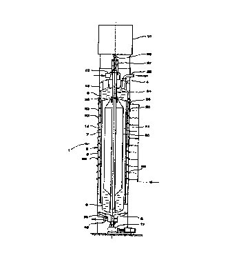
In the following description of a preferred
embodiment of the invention, reference will be made to
the attached drawing figure which shows a vertical
cross-section through a pressure diffuser equipped in
accordance with the preferred embodiment. In the
figure, certain details and elements have been omitted
which are not essential for an understanding of the
principles of the present invention, but which
represent known details and elements of pressure
diffusers.
DETAILED DESCRIPTION OF THE INVENTION
The figure shows a pressure diffuser 1 whose
basic construction is generally known. It has the shape
of a column comprising an outer pressure vessel 2 with
a cylindrical jacket 3, an upper end wall 4 and d lower
end wall 5. Inside the pressure vessel 2, and
concentric thereto, there is a screen unit 7 which is
vertically movable, with the upper and lower ends of
the screen unit sliding against an upper inner end wall
8 and a lower inner end wall 9, respectively. The

CA 02284693 1999-09-23
WO 98/45531 PCT/SE98/00579
- 3 -
latter walls are fixed to the pressure vessel 2 by bars
or the like. More precisely, the screen unit 7 is
movable to and fro between upper and lower end
positions wit=h the aid of one or more powerful
hydraulic cylinders arranged on the t=op of the column.
The hydraulic cylinders are indicated symbolically by
the numeral :LO. The cellulose pulp which is to be
washed is introduced into the top of the column through
an inlet line 12, continues via the space 13 between
the outer and inner upper end walls 4 and 8 to a gap 14
between the cylindrical jacket 3 of the pressure vessel
2 and the screen unit 7, and is finally led out through
an outlet line 15 at the bottom of the column. To make
the discharge easier, there are scrapers 16 which are
driven by a motor 17.
Washing liquid is introduced continuously
through a ser=ies of nozzles 20 distributed around the
circumference and length of the jacket 3, and onwards
through the ~~ulp in the gap 14, and through screen
openings in t=he screen unit 7, into the space inside
the screen unit. Thus, all fillable spaces inside the
screen unit 7 between the upper and the lower inner
column 8, 9 a.re filled with filtrate. From the space
inside the upper end wall 8, the used washing liquid -
the filtrate - is sucked out through an outlet line 22.
The hydraulic cylinder (not shown), or the
system of hydraulic cylinders, is connected via a
hydraulic bar 23 to a central pipe 24 which extends
slidably through this upper end walls 4 and 8 and down
into the bottom part: of the column. The central pipe 24
is moreover connected to the screen unit via radial,
vertical plates 25. At the top of the column there is a
so-called pressure-equalizing chamber 27 intended to be
able to rec=eive the cellulose pulp which is
continuously Eyed in the form of a suspension through
the inlet line 12, including during the upward return
stroke of the scref=n unit 7. The pressure-equalizing
chamber 27 communic=ates with the bottom part of the
column through the central pipe 24. In this context it

CA 02284693 1999-09-23
WO 98/45531 PCT/SE98/00579
- 4 -
should be pointed out that the pressure-equalizing
chamber 27 and the central pipe 24 are arrangements
which only exist in a specific type of pressure
diffuser, which is shown in the drawing. Other methods
of handling the inflow of cellulose during the upward
return stroke are also possible, for example where the
piston rod 23 can extend right down to and be connected
to the screen unit 7 in the same way as the central
pipe 24.
What has been described above belongs to the
prior art. The novel feature consists of a float body
30. According to the embodiment, the float body 30
consists of an elongate cylindrical vessel which
extends along essentially the entire length of the
screen unit and narrows at both ends and is securely
fixed to the screen body 7. The float body 30 is also
closed and contains air or, if appropriate, foamed
plastic in order to give the extra pressure strength.
It is concentric to the screen body 7 and has a smaller
diameter than the latter, so that an annular gap 31 is
formed between the float body 30 and the inside of the
screen unit 7. By virtue of the fact that the float
body 30 is fixedly connected to the screen unit 7, and
because the float body 30 is arranged in the filtrate-
filled volume inside the screen unit ? between the
inner end walls 8 and 9, the float body 30 gives the
screen unit 7 a buoyancy force which to d large extent
compensates the inherent weight of the screen unit,
which can amount to many tonnes, for example twenty
tonnes in existing cases.
The equipment functions in the following way,
with only those parts of the washing process which have
to do with the invention being described in detail. The
cellulose pulp which is to be washed is, as has already
been mentioned, fed continuously through the inlet line
12 and is discharged continuously through the outlet
opening 15. During the washing phase, the screen unit 7
is driven downwards at a speed which only slightly
exceeds the speed of the cellulose suspension's

CA 02284693 1999-09-23
WO 98/45531 PCT/SE98/00579
- 5 -
downward movement in 'the annular gap 14 between the
outer pressure vessel 2 and the screen unit 7. The
washing liquid is led in through the nozzles 20, passes
through the gap 19 during washing of the pulp in this
gap and accumulate~~ in the annular gap 31 between the
float body 30 and the screen unit 7, from where the
used washing liquid - the filtrate - which fills all
the fillable spaces between the upper and lower end
walls 8 and ~~ inside the screen unit 7 rises upwards
and is gradu~.lly led off througO the outlet line 22.
This downward movement takes place under the
countereffect of the buoyancy which the float body 30
exerts on the screen unit 7 in the liquid-fil led
volume.
When the screen unit 7 has reached its lower
end position, it is driven upwards at high speed during
the return stroke with the aid of the hydraulic
cylinder (not: shown) and under the effect of the
buoyancy fron; the float body 30. The used washing
liquid - the filtrate - in the space inside the upper
end wall 8, displaced by the float body 30, flows down
through the annular. gap 31 between the float body 30
and the screen unit 7 to the lower space inside the
lower inner end wall 9 and at the same time generates a
pressure surge in the radial direction which can
contribute to freeing the pulp bed from the screen
surface, a fact which facilitates the rapid upward
movement of the screen body. By dimensioning the
external diameter of the screen body 30 and
consequently t:he width of the gap 31, it is possible to
create optimum conditions in respect of, on the one
hand, the desired buoyancy and, on the other hand, the
acceptable flow resistance in the gap 31, and the
desired pressure surge for freeing the pulp bed from
the screen surface. The displacement of the float body
30 should theoefore amount to the weight of the screen
unit ~ 75'~~, preferably ~ SO',, expediently ~ 25'-:, while
the width of the gap 31 will amount to at least 5"~ of
the inner radius of. the screen unit 7, preferably 5 -

CA 02284693 1999-09-23
WO 98/45531 PCT/SE98/00579
6
25a;; and expediently 10 - 25'<; of the radius. In absolute
figures, the displacement should amount to at least 1
tonne, preferably at least 3 tonnes, but for most
existing pressure diffusers expediently at least
5 tonnes, or particularly preferably at least 10
tonnes.

Dessin représentatif
Une figure unique qui représente un dessin illustrant l'invention.
États administratifs

2024-08-01 : Dans le cadre de la transition vers les Brevets de nouvelle génération (BNG), la base de données sur les brevets canadiens (BDBC) contient désormais un Historique d'événement plus détaillé, qui reproduit le Journal des événements de notre nouvelle solution interne.

Veuillez noter que les événements débutant par « Inactive : » se réfèrent à des événements qui ne sont plus utilisés dans notre nouvelle solution interne.

Pour une meilleure compréhension de l'état de la demande ou brevet qui figure sur cette page, la rubrique Mise en garde , et les descriptions de Brevet , Historique d'événement , Taxes périodiques et Historique des paiements devraient être consultées.

Historique d'événement

Description Date
Demande non rétablie avant l'échéance 2004-03-30
Le délai pour l'annulation est expiré 2004-03-30
Inactive : Abandon.-RE+surtaxe impayées-Corr envoyée 2003-03-31
Réputée abandonnée - omission de répondre à un avis sur les taxes pour le maintien en état 2003-03-31
Lettre envoyée 1999-12-16
Inactive : Transfert individuel 1999-11-19
Inactive : Page couverture publiée 1999-11-18
Inactive : CIB en 1re position 1999-11-10
Inactive : Notice - Entrée phase nat. - Pas de RE 1999-10-27
Inactive : Lettre de courtoisie - Preuve 1999-10-26
Demande reçue - PCT 1999-10-22
Demande publiée (accessible au public) 1998-10-15

Historique d'abandonnement

Date d'abandonnement Raison Date de rétablissement
2003-03-31

Taxes périodiques

Le dernier paiement a été reçu le 2002-02-22

Avis : Si le paiement en totalité n'a pas été reçu au plus tard à la date indiquée, une taxe supplémentaire peut être imposée, soit une des taxes suivantes :

  • taxe de rétablissement ;
  • taxe pour paiement en souffrance ; ou
  • taxe additionnelle pour le renversement d'une péremption réputée.

Les taxes sur les brevets sont ajustées au 1er janvier de chaque année. Les montants ci-dessus sont les montants actuels s'ils sont reçus au plus tard le 31 décembre de l'année en cours.
Veuillez vous référer à la page web des taxes sur les brevets de l'OPIC pour voir tous les montants actuels des taxes.

Historique des taxes

Type de taxes Anniversaire Échéance Date payée
Taxe nationale de base - générale 1999-09-23
Enregistrement d'un document 1999-11-19
TM (demande, 2e anniv.) - générale 02 2000-03-30 2000-02-15
TM (demande, 3e anniv.) - générale 03 2001-03-30 2001-02-15
TM (demande, 4e anniv.) - générale 04 2002-04-01 2002-02-22
Titulaires au dossier

Les titulaires actuels et antérieures au dossier sont affichés en ordre alphabétique.

Titulaires actuels au dossier
KVAERNER PULPING AB
Titulaires antérieures au dossier
BJORN KARLSSON
Les propriétaires antérieurs qui ne figurent pas dans la liste des « Propriétaires au dossier » apparaîtront dans d'autres documents au dossier.
Documents

Pour visionner les fichiers sélectionnés, entrer le code reCAPTCHA :


Pour visualiser une image, cliquer sur un lien dans la colonne description du document (Temporairement non-disponible). Pour télécharger l'image (les images), cliquer l'une ou plusieurs cases à cocher dans la première colonne et ensuite cliquer sur le bouton "Télécharger sélection en format PDF (archive Zip)" ou le bouton "Télécharger sélection (en un fichier PDF fusionné)".

Liste des documents de brevet publiés et non publiés sur la BDBC .

Si vous avez des difficultés à accéder au contenu, veuillez communiquer avec le Centre de services à la clientèle au 1-866-997-1936, ou envoyer un courriel au Centre de service à la clientèle de l'OPIC.

({010=Tous les documents, 020=Au moment du dépôt, 030=Au moment de la mise à la disponibilité du public, 040=À la délivrance, 050=Examen, 060=Correspondance reçue, 070=Divers, 080=Correspondance envoyée, 090=Paiement})


Description du
Document 
Date
(aaaa-mm-jj) 
Nombre de pages   Taille de l'image (Ko) 
Dessin représentatif 1999-11-17 1 7
Description 1999-09-22 6 266
Abrégé 1999-09-22 1 44
Revendications 1999-09-22 2 72
Dessins 1999-09-22 1 22
Rappel de taxe de maintien due 1999-11-30 1 111
Avis d'entree dans la phase nationale 1999-10-26 1 193
Courtoisie - Certificat d'enregistrement (document(s) connexe(s)) 1999-12-15 1 115
Rappel - requête d'examen 2002-12-02 1 113
Courtoisie - Lettre d'abandon (taxe de maintien en état) 2003-04-27 1 176
Courtoisie - Lettre d'abandon (requête d'examen) 2003-06-08 1 165
Correspondance 1999-10-24 1 14
PCT 1999-09-22 7 269