Note : Les descriptions sont présentées dans la langue officielle dans laquelle elles ont été soumises.
CA 02284759 1999-09-30
PROCESS FOR MANUFACTURING OR REPAIRING TURBINE ENGINE
OR COMPRESSOR COMPONENTS
Background of the invention
l.Field of the Invention
The present invention relates to a process for producing or repairing
components
of turbine engines, especially gas turbines. The process may be used to
manufacture or
repair the turbine or compressor or fan blades or vanes as such, or may be
used to
manufacture a rotor in which the turbine or compressor blades are integrally
formed
with the rotor disk.
2.Prior Art
Gas turbine engines have three main sections, namely fan, compressor and
turbine, each of which may have several stages connected through a central
shaft. Each
stage has one rotor and one stator. Each rotor used in a gas turbine engine
consists of a
disk fastened mechanically to a central shaft and blades of airfoil shape
attached
mechanically to the rim of the disk. Each stator has vanes, also of airfoil
shape, attached
at an outer end to the engine casing and at the inner end to a shroud.
Depending on the
2 0 size of the engine, each rotor and stator may contain dozens of blades or
vanes. The
present invention is primarily concerned with manufacture and repair of the
rotor blades,
especially of the turbine section, which are subject to high heat and stress,
but may also
be used to manufacture or repair the stator vanes. The term
"turbine/compressor blades"
as used herein is intended to include the turbine and compressor and also fan
rotor
2 5 blades, and the vanes used in the fan, compressor and turbine stages.
Normally, the blades and disk of each rotor are manufactured separately.
Individual blades are made using a number of processes including hot forging,
investment casting, directional solidification of melts, etc., depending on
the material
3 0 and functional requirements. For attaching the blades to the disks, either
"dove-tail" or
"fir-tree" geometry is imparted to the base of the blades, during casting or
forging, and
1
CA 02284759 1999-09-30
may require post machining. The disk is usually forged, and slots of suitable
dove-tail or
fir-tree shape for the blade attachments are machined. The final operation is
the
assembly of parts to form a turbine.
The turbine blades may be hollow, with acute angled holes on the leading and
trailing edges as well as on the walls and tip. The cooling holes are now
often drilled by
a high powered Nd:YAG laser. The hollow geometry with cooling holes helps keep
the
blade material cooler under the operating conditions, and thereby maximises
the
operating life.
The conventional process for making turbine/compressor rotors has the
following drawbacks:
1. The various processes of making the blades, whether by forging, investment
casting, or directional solidification, and the subsequent machining, are
expensive;
2. Since the blades are attached mechanically to the disks, considerable cost
is
involved with joint preparation, both for the joint parts of the blades and of
the disk.
Accurate assembly is required to maintain the desired orientation of the
blades. The
joints between the blades and the disks are subject to fretting fatigue at the
interfaces of
the joints and this reduces the life of the rotor.
2 0 3. The drilling of cooling holes in the blades is an expensive process and
there
are problems with drilling acute angled holes required by newer designs of
blades. Also,
there is a limit to the smallness of hole diameter which can be produced by
laser drilling;
it would be preferable to use a large number of holes smaller than those which
can be
drilled by a laser.
Attempts have been made to produce turbine/compressor blades by a process
analogous to laser cladding or welding in which a laser is traversed over a
metal surface
while powdered metal is supplied to the surface so that the added metal is
fused to the
underlying surface. By this means layers of metal can be built up to form an
article
3 0 having a shape determined by a computer-guided laser and metal delivery
means.
2
CA 02284759 1999-09-30
Such attempts have been made by Sandia National Laboratories, of
Albuquerque, New Mexico, as described in a paper entitled "Laser Engineered
Net
Shaping (LENS) for Additive Component Processing" by Dave Keicher, presented
at a
conference entitled "Rapid Prototyping and Manufacturing '96" held by SME at
Dearborn, Michigan, U.S.A., in April 1996. Initially, experiments were made
with a
single point, off axis (side) powder delivery nozzle, but this was found to
give strong
directional dependence on the deposition height. The single side powder nozzle
was
abandoned in favour of a co-axial powder feed in which single laser is used
normal to
the workpiece surface being coated and which is co-axially surrounded by a
series of
l0 powder delivery tubes all feeding into the region at which the laser beam
strikes the
workpiece. In a later 1998 paper from the same laboratories it was stated
that, with the
coaxial powder feed arrangement, the best surface finish achieved was 8
micrometers Ra
(roughness average) on the walls; this was after years of development.
Another similar process has been developed by Los Alamos National laboratory,
New Mexico, as described in a paper entitled "Directed Light Fabrication"
presented at a
1994 ICALEO (International Congress on Applied Lasers and Electro-Optics)
conference. This is also described in U.S.Pat. No.5,837,960, which issued
Nov.l7, 1998
to Lewis et al. The process also used a single laser normal to the workpiece
surface and
2 0 surrounded by a coaxial arrangement of powder delivery tubes. Articles
produced by the
process of this patent are said to have "relatively rough" surfaces. In a
publication of
1998 relating to this process a surface finish of around 20 micrometers Ra was
reported.
Other processes for producing turbine blades by laser welding or deposition
are
2 5 described in the following patent publications:
U.S.Pat.No.5,160,822, which issued Nov.3, 1992 to Aleshin;
U.S.Pat.No.5,900,170, which issued May 4, 1999 to Marcin, Jr., et al.;
Can.Pat.Appln.No.2,012,449 to Rathi et al., published Nov. 15, 1990;
Can.Pat.Appln.No.2,085,826 to Williams, published June 20, 1993; and
3 0 Can.Pat.Appln.No.2,170,875 to Goodwater et al., published March 9, 1995.
3
CA 02284759 2006-04-13
In addition, U.S.Pat.No.5,038,014, issued Aug.4, 1991 to Pratt et al.,
describes a
laser welding technique for making turbine or compressor blades, which is said
to be
suitable also for forming the rotor blades integrally with the rotor disk. The
patent
suggests using a conventional laser cladding process with a normal or vertical
laser
beam and a powder feed tube set at an angle. It is evident from tests done by
applicants
that there are major problems with this method:
1 ) The height of the airfoil will be uneven due to the multi-directional
nature of
the beads used to build the blade and the fact that this gives uneven
deposition, and
2) The surface finish will be very poor, and it is expected that machining
will be
necessary.
The present invention provides a process which can be used either to produce
or
to repair blades of rotors or vanes of stators used in gas turbines and other
turbines by
addition of metal to a base using a laser process similar to those discussed
above, but
having different laser/ metal delivery configurations. The process can produce
parts with
such accuracy that machining may be avoided. The basic process will be
referred to
herein as "laser consolidation". However, it will be noted that in the
literature and
patents referred to the same basic process of building a component has been
referred to
by many different names, e.g. "laser engineered net shaping", "directed light
2 0 fabrication", "linear translational laser welding", "energy beam
deposition", "sequential
layer deposition", "energy beam casting", and "laser sintering". The term
"laser
consolidation" is intended to include processes of this type in which a laser
beam is used
to melt metal, delivered in powder or wire form, to a surface, to build up a
shaped object
by controlling movement of the beam and metal delivery means.
Summary of the Invention
Broadly, the invention makes use of the fact that laser consolidation can be
performed accurately enough for fabrication of turbine/compressor blades,
which need
3 0 little or no subsequent machining,.
4
CA 02284759 1999-09-30
In accordance with one aspect of the invention, a process for producing or
repairing a turbine/compressor blade by laser consolidation includes the known
features
of moving a laser beam relative to a surface of a metal substrate to irradiate
the substrate
metal and simultaneously supplying a stream of metal to the surface via supply
means
having a fixed relationship to the laser beam, so that the laser beam melts a
thin layer of
the metal substrate and also melts the metal being delivered to the substrate
and thus
forms a band of fused metal on the surface, and repeating this step until a
desired blade
is built up or repaired. The process of the invention is characterized in that
the supply
means delivers the metal substantially along a path normal to the surface, and
in that the
laser beam is one of a plurality of laser beams each orientated at an acute
angle to the
normal to the surface, the laser beams being spaced around the supply means.
The stream of metal may be provided by a wire, the supply means being a wire
guide. Usually however, the stream of metal will be a stream of metal powder
delivered
through a powder tube normal to the surface being built up or repaired.
The acute angle is between 5 and 45°, and preferably the laser beams
are at equal
acute angles to the normal to the surface, and are equally spaced around the
metal
2 0 powder or wire supply means. In the preferred arrangement four of the
lasers are
provided spaced equally around a powder tube which forms the supply means,
each at
an angle of between 5 and 45° to the normal to the surface.
The metal substrate may be the periphery of a turbine or compressor or fan
rotor
2 5 disk, so that the process produces blades which are integral with the
disk. Unlike in the
Pratt et al. patent referred to above, this process will produce a finish good
enough not to
require post-machining, specifically being good to about 1 or 2 micrometers
Ra, so that
this is a very practical way of making integral disks and blades.
3 o The process is also very useful for producing a hollow blade by
controlling
movement of the supply means, e.g. the powder tube, and of the laser beam, to
form
5
CA 02284759 1999-09-30
walls defining the blade and surrounding a cavity. Holes for cooling fluid can
be formed
in the walls while the blade is being built by placing a wire on a wall part
which has
been built, and continuing the formation of the wall around the wire, and
later removing
the wire to leave a bore through the wall. The wires may be quite fine, and
produce
holes smaller than those which can be produced by laser drilling. The process
can also
produce a double-walled turbine blade in which the cooling fluid is circulated
in the
space between the double walls. -
In accordance with another aspect of the invention, the method is generally
the
same as described above except that instead of using a series of laser beams
spaced
around supply means such as a powder delivery tube normal to the surface, the
supply
means is slanted at a first acute angle to the normal to the surface, and a
single laser
beam is orientated at a second acute angle to the normal to the surface, the
laser and
supply means being located at opposite sides of the normal and in the same
plane. Both
the acute angles are preferably between 5 and 45° to the normal to the
surface. In this
case, a good surface finish is obtained on the side nearest the laser, but the
opposite side
may require post machining.
As before, the metal substrate may be the periphery of a turbine rotor disk,
so
2 0 that the process produces blades which are integral with the disk. The
process may also
repair damaged blades. Also, as before, the process may be arranged to produce
a
hollow blade by moving the supply means and laser beam to form walls defining
the
blade and surrounding a cavity. Again, holes can be formed through the hollow
walls by
putting wires in place during building of the wall, and later removing the
wires.
Brief description of the drawings
A preferred embodiment of the invention will now be described by way of
example with reference to the accompanying drawings, in which;
Fig. l is an elevation of apparatus used for producing an integral blade on a
rotor
3 0 disk, using four lasers, and looking along the plane of the disk;
6
CA 02284759 2006-04-13
Fig.3 is a view similar to Fig.l of another apparatus of the invention, this
apparatus having single, separate laser nozzle and powder delivery tube;
Fig.4 is a view of the apparatus of Fig.3 but looking perpendicular to the
plane of
the disk;
Fig.S is a perspective view of the top portion of a double-walled hollow
blade;
and
Fig.6 is a sectional elevation on lines 6-6 of Fig.S.
Detailed Description
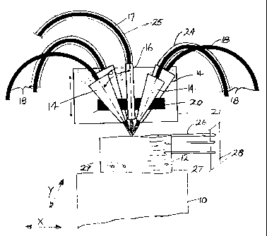
Fig.l schematically shows the set-up used for this invention. The apparatus
includes a rotary holder (not shown) for the disk 10 (seen edgewise in Fig. l
), the holder
being of the kind having a computer controlled rotary chuck for rotating a
metal
workpiece such as disk 10 as blades 12 are formed integrally on the periphery
of the
disk. The holder is mounted on a CNC (computer numerical control) table to
provide
horizontal translational movement both along an X axis, indicated by the arrow
X in
Fig. l and which is parallel to the axis of the disk, and along the Y axis
also indicated by
2 0 an arrow and which is perpendicular to the disk axis. A computer also
controls rotation
of the holder about the disk axis.
The arrangement of lasers and supply means in Fig.l, which is mounted above
the table. It has four laser nozzles 14 arranged evenly around a central metal
powder
2 5 delivery tube 16, the lasers providing beams directed inwardly at equal
inclinations to
the powder tube. The powder tube is normal to the surface of the blade being
produced,
and is usually vertical. It is connected to a powder conduit 17. Each laser
nozzle 14 is
inclined inwardly so that the laser beam axes meet that of the delivery tube
16 at or close
to a common location at the top of the workpiece, namely blade 12. The angle
of
3 0 inclination 6 to the vertical, which is also the normal to the surface
being
7
CA 02284759 1999-09-30
treated, is preferably between S and 45°. When viewed from the top, as
in Fig.2, the
laser nozzles are spaced equally around tube 16 at 90° apart.
The laser nozzles 14 and powder tube 16 are all held in place by a holder 20
mounted on head 21. This head is fixed against movement in the horizontal
plane, but is
computer controlled to rise vertically as layers of material are built up on
the workpiece.
The head therefore provides a Z-axis component of movement, while -the CNC
controlled table provides horizontal movement of the disc in the X and Y
directions as
indicated, thus providing the necessary relative movement between the lasers
and feed
tube and the disk. The arrangement is such that any desired form of
turbine/compressor
blade can be built up on the disc 10 by suitable movements of the table the
head 21,
while the lasers 14 melt the surface of the workpiece and while the tube 16
supplies
powdered metal to the melted area of the workpiece. During the building of a
blade the
disk is held against rotational movement so that the axis of the blade remains
vertical;
the disk is only rotated to index the disk from one blade position to the
next. It may be
noted that since the disk is not rotated during the building of a blade,
initially the
powder tube will not be quite normal to all points on the disc surface, and
references to
the "normal" to the surface are to be understood as being often a few degrees
off the
exact perpendicular angle.
In operation, the laser melts a thin surface layer of the base, or of the
previously
deposited metal, along with the powder being delivered through tube 16, to
create a
layer or band of fused metal powder of known height and width. The head 16
then raises
the laser nozzles 14 and tube 16 by a predetermined amount, for example a few
2 5 thousands of an inch, and a further layer is formed on the first; this
time the powder and
a part of the previous layer are melted. This continues until the desired
height of blade is
achieved.
Control of the process is through a NC (numerical control) file. A CAD
3 0 (computer aided design) model of the blade, through the use of suitable
software, is
sliced into layers of known thickness, this being controlled by the process
parameters
8
CA 02284759 1999-09-30
and saved in the NC file. The program not only determines the path of movement
of the
laser beam and delivery tube combination relative to the workpiece held by the
rotary
holder, but also determines the vertical movement of the head 21 needed to
produce
layers which have a build-up height determined by the operating parameters.
The laser nozzles may each have a separate small laser, or all four laser
nozzles
may be supplied with laser light from a single laser provided with a beam
splitter which
divides the laser beam into four beams which are then transmitted to the laser
nozzles by
optical fibers 18. The lasers producing the beam are preferably of the Nd:YAG
type.
The laser nozzles are connected by conduits 24, which are coaxial with the
cables 18, to a source of shielding gas such as argon; this helps to protect
the laser lens
inside nozzle 18 from molten metal spatter, and also protects the metal being
deposited
from oxidation. A shielding gas is also delivered with the powdered metal
along conduit
17 to the powder tube 16.
This arrangement using several lasers has the advantage of allowing control of
the manner in which the workpiece is being heated. The lasers can be either
all focused
on the same location to concentrate the energy on a small area, or can be
focused on
2 0 slightly spaced areas to produce a bigger spot. In making a hollow blade,
the first
arrangement will produce a thin wall, and the second will produce thicker
walls. When
using the bigger spot, power density within the enlarged spot can be
maintained at the
desired level by controlling the power of the individual laser beams.
2 5 A further advantage of the multiple laser beam arrangement is that pre-
heating
and post-heating of the built-up layer can be accomplished in a single pass.
Pre- and
post-heating becomes very important when hard materials, which are sensitive
to
thermal shock, or materials that undergo cooling rate dependent
transformations, are
used for building up parts. Using this arrangement, one beam can be focused
ahead of
3 0 the point of build-up for pre-heating, while another beam can be made
incident at a spot
9
CA 02284759 1999-09-30
behind the point of build-up for post-heating and controlling the cooling
rate, and the
two other beams can be used for build-up of metal.
Figs. l and 2 also show how holes can be produced in the walls of a hollow
blade
while the blade is being built up. This is done by placing wires, such as
wires 26, on the
top of a wall part at the positions where holes are required, and then
continuing the
building process around the wires. When the blade is complete the wires are
pulled out
to leave holes 27 of the same diameter as the wires. Wires of aluminum or
copper are
suitable, since they reflect much of the laser light and do not melt into the
wall. Wires of
quite small diameter, for example of 0.13 mm diameter can be used, to produce
holes of
similar diameter, which is smaller than can be produced by laser drilling.
Also, wires of
non-circular section, for example square, rectangular, or triangular, can be
used to
produce similarly shaped holes. A jig or holder, for example as indicated at
28 in Fig.l,
can be provided to hold a large number of the wires in desired orientation.
With this
procedure, there is no difficulty in making holes at acute angles to the wall
of the blade.
In the alternative arrangement of Fig.3, the disk 10 is similarly supported by
a
rotary and XY motion controlled table (not shown), but the arrangement of
laser and
powder tube are different. Here, the holder 20 and head 21 support a single
laser nozzle
2 0 14' which directs a laser beam 1 S inclined at an acute angle ~,°
to the vertical V, and also
support a metal powder delivery tube 16' which has its axis oppositely
inclined at 13° to
the vertical. Powder is fed to this tube by conduit 1 T. The laser producing
the beam is
again preferably of the Nd:YAG type, mounted separately, the laser light being
transmitted to the nozzle by the optical fiber 1 f.The laser nozzle is
connected by a
2 5 separate conduit 24' to a source of shielding gas such as argon.
Hollow turbine blades have been produced with both the central powder
feed/multiple laser beam process of Figs.l and 2, and the single off axis
laser/off axis
process of Figs.3 and 4, showing excellent consistency and quality in the wall
thickness
3 0 and heights, and with a surface finish of 1 to 2 micrometers Ra. With this
type of surface
finish and the final operation of shot peening required to impart compressive
residual
CA 02284759 1999-09-30
stress for improved fatigue properties, no further machining is required.
Sample blades
have been made using IN-625 and IN 738 metal alloy powders; both these are
nickel
base alloys of the type known as "superalloys" in the aircraft industry.
Cobalt and iron
based superalloys, and intermetallics such as titanium and nickel aluminides,
may also
be used.
Figs.S and 6 show a double-walled hollow turbine blade 32, having an inner
partition wall 34 spaced within the outer wall to provide a space 35 between
the walls
for the circulation of cooling gas. The space 35 is preferably connected to a
return
conduit for the cooling gas, which is preferably delivered outwardly through
the center
of the inner wall 34, as indicated in Fig.6. After the process has been used
to build up
the walls, the blade is completed by welding a cap 36 across the top.
While the Nd:YAG type laser with fiber optic beam delivery has been used for
this process, other lasers without fiber optic beam delivery, such as a carbon
dioxide
laser, a diode pumped YAG laser, or another diode laser, could also be used.
The process may also be used to repair turbine blades, which in service
experience very hostile environments and undergo different kinds of damage. As
they
2 0 are expensive, they are repaired and reused. During an overhaul, damaged
blades are
taken out of the engine and sorted to select the reparable blades. The damaged
area,
usually on the tip for hot section blades, is removed usually by machining and
repaired.
Hitherto such repair has usually been made by welding. However, the processes
described above are well suited to repair of blades after the damaged area has
been
2 5 ground away. Advantages of using this laser consolidation process for
repair of worn
blades, as compared to the conventional welding process, are as follows:
1. Choice of repair material; conventional welding is limited to certain
weldable
materials.
2. No post-machining of the shape is required; the conventional welding
process
3 0 requires expensive machining and hand finishing.
11
CA 02284759 1999-09-30
3. Sound metallurgical microstructure; welding process may leave porosity and
cracking
if not controlled properly.
4. Minimal heat affected zone, compared with welding which generally causes a
large
heat affected zone which deteriorates the properties of the blade material
adjacent to the
weld.
S. Full automation is possible, giving an economical process with improved
quality.
Although in the embodiments shown the substrate for building the blades is a
rotor disk, in practice the blades may also be built up on a conventional
blade joint.
12