Note : Les descriptions sont présentées dans la langue officielle dans laquelle elles ont été soumises.
CA 02284843 1999-09-14
WO 98/48372 PCT/US98/07685
OCCUPANT TYPE AND POSITION DETECTION SYSTEM
BACKGROUND OF THE INVENTION
The present invention relates generally to motor
vehicle crash discrimination systems utilized for actuating or
deploying a passenger safety restraint, and more specifically
to a system and method for detecting occupant seating
conditions so as to optimize deployment of a passenger safety
restraint.
Conventional vehicle crash discrimination systems
typically employ at least one mechanical, electromechanical, or
electronic acceleration sensor affixed to the vehicle for
sensing vehicle acceleration. The output of the sensors are
supplied to a discrimination circuit for comparison to a
predetermined threshold value. I:. the predetermined threshold
value is exceeded, the discrimination circuit will output a
signal which actuates or deploys <3 passenger safety restraint,
such as an air bag or passive seat belt mechanism.
However, conventional mechanical or electromechanical
accelerometer based crash discrimination systems do not account
for variations in passenger/occup,ant conditions in determining
whether to actuate the safety restraint. More specifically,
conventional accelerometer based crash discrimination systems
are generally designed to assume nominal conditions, such
as 50th percentile male, actual presence of a vehicle occupant,
and failure of an occupant to wear a seat belt. The assumption
of these crash conditions are necessary to insure proper
actuation of the safety restraint: when severe deceleration of
the vehicle is detected by the accelerometer. Such assumptions
inherently cause unnecessary, undesired, or improperly-timed
actuation of the safety restraint in conditions where no
occupant is present, in marginal crash situations where a seat
belt provides sufficient safety pi:otection for the occupant, or
in situations where the occupant is improperly positioned
relative to the safety restraint: such that actuation of the
safety restraint could potentially injure the occupant.
-1-
CA 02284843 1999-09-14
WO 98/48372 PCT/US98/07685
Thus, since conventional crash discrimination systems
can not accommodate various occupant conditions which affect
the desirability of actuating the safety restraint, they have
not proven to be completely satisfactory. In response, the
prior art has attempted to overcome these deficiencies by
providing arrangements which are generally directed at
detecting occupant presence, size, or position relative to some
fixed structure in the vehicle. The following are examples of
such prior art arrangements.
US 5,413,378 to Steffens, Jr., et al disclose a
system for controlling an occupant restraint, such as an air
bag, wherein the system utilizes a combination of a set of
ultrasonic occupant position sensors, and various seat and
occupant weight sensors, to determine occupant weight and
position relative to fixed structure with the vehicle.
US 5,398,185 to Omura discloses a system for
optimizing deployment of passenger restraint devices which
utilizes a combination of a plurality of seat sensors, a card
reader for inputting data regarding the physical
characteristics of the occupant, and two telecameras to compute
a value characteristic of each interior vehicle element and the
occupant's estimated behavior relative thereto.
US 5,366,241 to Kithil discloses an overhead-mounted
air bag deployment system which utilizes an overhead passenger
sensor array to sense position and velocity of an occupant's
head so as to control deployment of an air bag, and to detect
and provide warning when the occupant is in an unsafe seated
condition.
US 5,074,583 to Fujita et al disclose a vehicle
collision detection system which utilizes a plurality of seat-
mounted sensors to detect occupant seating condition, position,
and size in order to optimize inflation of an air bag in a
vehicle collision.
In addition, commonly owned U.S. Patents 5,446,661
and 5,490,069 each disclose a method and system for vehicle
crash discrimination which continuously detects various vehicle
occupant positions for optimizing a discrimination analysis to
-2-
CA 02284843 1999-09-14
WO 98/48372 PCT/US98/07685
achieve increased efficiency and reliability in actuating a
safety restraint.
While these arrangements may have provided an
improvement in efficiency over conventional crash
discrimination systems, there still exits a need for a crash
discrimination system which can further optimize or tailor air
bag deployment based on the specific type of occupant present
in the vehicle. More specifically, with the increased use and
availability of air bags in motor vehicles has come the
realization that deployment of an air bag in certain crash
situations, and with certain types of occupants, such as
infants strapped into a child safety seat, has the potential of
causing more harm to the occupant 'than if the air bag were not
deployed.
As noted above, this problem has become particularly
acute with infant safety seats. Th.e prior art has attempted to
distinguish passengers from infant child seats by using
conventional distance measuring techniques to detect the amount
and extent of possible occupant mo~Jement, or alternatively has
used weight sensing arrangements to detect the weight of any
object which might be located on the vehicle seat. In either
arrangement, threshold values are used to classify an object as
either a passenger or an inanimate: object.
However, simply using 'weight sensors or movement
monitoring has not provided the level of discrimination between
occupant types or the reliability necessary to achieving
effective "smart" control over air bag deployment. As a
result, a need still exist for a system which can automatically
and continually determine occupant type and position in a
reliable and cost effect manner.
SUMMARY OF THE INVENTION
It is therefore an object: of the present invention to
provide a system and method which automatically determines the
type of occupant in a vehicle seat, as well as the location of
that occupant within the seat relative to fixed structure in
the interior of the vehicle, such as the dashboard or steering
-3-
CA 02284843 1999-09-14
WO 98/48372 PCT/US98/07685
wheel, so as to increase efficiency and reliability in
actuating or deploying a safety restraint such as an air bag.
It is another object of the present invention to
provide a system and method which is capable of detecting the
presence of either a person, a rearward facing infant car seat,
a forward facing infant car seat, or a box or other inanimate
object, so as to increase efficiency and reliability in
actuating or deploying a safety restraint such as an air bag..
It is a further object of the present invention to
provide a system and method which determines if an occupant is
in an unsafe seated position to optimize control over
deployment of an occupant safety restraint such as an air bag
or other passive restraint device.
In accordance with these and other objects, the
present invention provides a system and method which detects
occupant position and type which utilizes a single camera unit
positioned for example at the driver or passenger side A
pillar. The present invention provides a system and method
which distinguishes between objects, forwardly or rearwardly
facing infant seats, and adult occupants by periodically
mapping an image taken of the interior of the vehicle into
image profile data, and utilizing image profile matching with
stored reference profile data to determine the occupant or
object type. Instantaneous distance is also measured and
changes in the measured distances are tracked. All of this
information is than used to optimize deployment control of at
least one passenger safety restraint.
Thus, in accordance with a first aspect of the
present invention, a system for determining vehicle occupant
type and position relative to a fixed structure within the
vehicle comprises an imaging means mounted at a single location
within the vehicle interior and having a predetermined field of
view so that a front driver side seat and a front passenger
side seat are both simultaneously viewable by said imaging
means, but not simultaneously in focus as described more fully
hereinbelow. The imaging means generates an output signal
representative of an instantaneous position for any object
-4-
CA 02284843 1999-09-14
WO 98/48372 PCT/US98/07685
located within the field of view. The system further includes
means for storing predetermined object profile data
characteristic of a plurality of different types of objects
when situated in either front seat of the vehicle, and a
processor means for identifying tlae type of object located in
the front seats of the vehicle by comparing the imaging means
output signal to the predetermined object profile data.
In accordance with a second aspect of the present
invention, a method for determining position of an object
located in a vehicle relative to a fixed structure within the
vehicle comprises the steps of genE~rating two-dimensional image
data representative of any objects located within a front
seating are of the vehicle, generating a two-dimensional range
grid by vertically dividing the front seating area into a
plurality of independent region: each representative of a
predetermined size of the vehicle interior, wherein the fixed
vehicle structure such as the instrument panel is located
proximate to one end region, and the vehicle front seats are
located proximate with the opposite end region, detecting
lateral location of the obj ect relative to a narrow depth of
focus reference plane using a de-blurring filter, and
determining distance from the fixEad structure by comparing the
generated image data with the rangE=_ grid to detect which if any
of the plurality of regions are occupied by an object.
In achieving both of these aspects, the system and
method of the present invention further comprise discriminating
between objects and occupants; ~~-pillar positioning of the
imaging system; use of a perspective angle correction lens; use
of a two-dimensional range grid; tracking the change in
instantaneous occupant position to predict a crash situation;
optimization of passenger restraint deployment based on the
identification of occupant type and position; generating the
two-dimensional range grid by either etching the grid on a lens
element, printing the grid on a CCD element, or utilizing
suitable programming in a processor means; and estimating
occupant lateral distance from a fixed vehicle interior
component by utilizing a narrow depth of focus lens in
-5-
CA 02284843 1999-09-14
WO 98/48372 PCT/US98/07685
combination with suitable electromechanical or image processing
auto-focus techniques.
The present invention will be more fully understood
upon reading the following detailed description of the
preferred embodiment in conjunction with the accompanying
drawings.
BRIEF DESCRIPTION OF THE DRAWINGS
Fig. 1 is a schematic illustration of a vehicle
occupant type and position detection system in accordance with
the present invention;
Fig. 2 is a side view of the vehicle interior showing
location of the system of the present invention;
Fig. 3 is a downward view of the vehicle interior
illustrating the field of view for the system of the present
invention;
Figs. 4 (a) and (b) are a side view of a "person"
type occupant and the corresponding two dimensional ranging
grid image of the present invention;
Figs. 5 (a) and (b) are a side view of an infant
safety seat and the corresponding two dimensional ranging grid
image of the present invention; and
Fig. 6 is a flowchart illustrating the operation of
the present invention.
DETAILED DESCRIPTION OF THE PREFERRED EMBODIMENTS)
Referring to Fig. 1, there is shown a system 10 which
determines vehicle occupant position and type in accordance
with the present invention. In accordance with the preferred
embodiment, system 10 is suitably adapted for mounting in a
single location, such as the driver or passenger side A-pillar
location as shown in Fig. 2, so as to have a field of view
allowing the system to "see" any region within the driver side
seat and the passenger side seat area for a given focal depth.
The use of a single location advantageously reduces the amount
of necessary hardware, and therefore the cost and complexity of
manufacturing and installation of the present invention.
More specifically, in accordance with the preferred
embodiment, a single camera unit 12 is located at the A-pillar
-6-
CA 02284843 1999-09-14
WO 98!48372 PCT/US98/07685
or similar location so as to have a perspective field of view
simultaneously covering both driver and passenger side seats.
The camera unit 12 is preferably a low light infra red (IR)
sensitive type camera system, and is arranged to provide all
light operation through the inclu:~ion of a supplemental light
source, such as represented by a:n LED 14. However, one of
ordinary skill in the art will readily appreciate that other
types of camera systems may be suitable, and as such the use of
an IR camera system 12 is not to be construed as limiting the
present invention.
A perspective angle correcting lens 1& is employed to
translate the perspective image of the interior of the vehicle
into a two-dimensional image signal which is then output to an
image processor 18. In other words, lens 16 is optically
designed to effectively remove the "perspectiveness" of the
image created by the slant angle of the camera 12 with respect
to a plane passing perpendicular to the instrument panel
through the center of the passenger seat, as more clearly shown
in Fig. 3. The correction lens 16 removes distortion in the
image pixels inherently caused by the perspective view and
makes the pixels all equal in ac1_ual distance spacing as if
being two-dimensionally viewed from the side of the vehicle.
In further accordance with the present invention,
system 10 utilizes a de-blurring filter arrangement 19 in
conjunction with a narrow depth of focus reference plane. With
a narrow depth of focus, points along a perpendicular plane are
in focus, and objects either farther or closer than this plane
are out of focus. Thus, the location of an object relative to
the focus plane can be inferred from the amount of blur in the
image, i.e., the farther an object is laterally displaced from
the focus plane, the more the image will be blurred.
The de-blurring filter, while symbolically shown in
Fig. 1, is preferably implemented as an algorithm subroutine in
image processor 18. Therefore, with a narrow depth of focus
and de-blurring filter arrangement, image processor 18 is able
to infer or estimate the location of an object relative to the
focus plane, while also being ab:Le to ignore or distinguish
CA 02284843 1999-09-14
WO 98/48372 PCT/US98/07685
background clutter within the viewable image, such as door
features or the driver depending on which side of the car the
system is located, from the desired image of the occupant or
object within the seat.
The system 10 further includes a grid pattern 20 that
is either etched on the lens 16, screen printed on a CCD, or
implemented by suitable programming within the image processor
18. This grid pattern is customized for each model of
automobile, and as best illustrated in Figs 4(a)-(b) and 5(a)-
(b) provides an actual distance spacing metric for the pixels
in the image along the plane perpendicular to the instrument
panel. As described hereinbelow, the grid pattern 20 is the
mechanism by which the image processor 18 will be able to
measure the actual distance of objects within the image focal
plane, and to otherwise detect dominate features of an object
or occupant located in the vehicle seat. The grid is
effectively normalized by using lateral location derived from
the narrow depth of focus reference plane and the de-blurring
filter arrangement.
In addition, the light source is preferably etched
with a matching pattern of grid marks. The relative warping of
the transmitted light by the occupant provides for detection of
fine shape features which may not be otherwise discernable in
poor lighting conditions due to reduced image contrast. Such
a warped grid analysis also provides a three-dimensional
profile of the occupant which can be used in conjunction with
the detected lateral distance to provide comprehensive
information regarding occupant size, shape, and location within
a vehicle seat.
The overall operation of the present invention as
well as the remaining elements of Fig. 1 will now be discussed
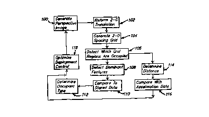
in context with the flow chart shown in Fig. 6. At step 100,
the camera unit 12 generates a perspective image signal which
is translated at step 102 by lens 16 into a two-dimensional
image data signal representative of the profile of any objects
located within a front seat of the vehicle. At step 104, a
two-dimensional spacing or range grid is created by vertically
_g_
CA 02284843 1999-09-14
WO 98/48372 PCT/US98/0?685
dividing the two-dimensional image of the front vehicle seating
area into a plurality of independent regions each
representative of a predetermined ;size of the vehicle interior.
The grid is oriented so as to substantially locate the fixed
vehicle structure at one end region, and the vehicle front
seats substantially at the opposite end region, as particularly
shown in Figs 4 (b) and 5 (b) .
At step 106, the two-d_~mensionally generated image
data is analyzed against the spacing grid to detect which if
any of the plurality of regions are occupied by an object or
occupant. The image processor 18 utilizes an image analysis
algorithm which detects the dominant features and position of
the object located in the vehicle seat at step 108. These
features include the relative extent of the vertical portion of
the occupant relative to the horizontal portion as shown in
Figs . 4 (b) or 5 (b) .
Object profile data representative of a set of
reference features of various types of occupants, such as
humans, forward and rearward facing infant safety seats, or
other inanimate objects, are stored in a suitable memory device
21, such as a RAM or EEPROM. 'rhe stored sets of reference
features are scaled to allow identification of a complete range
of occupant sizes, i.a., small children to large adults. In
addition, since there are a variety of different sized infant
seats, a size invariant classification of reference features is
provided for proper identification of infant seats. Image
processor 18 than determines occupant type at step 112 by
mapping or comparing the detected dominant features of the two
dimensional image signal with the set of reference features
stored in memory 21 at step 110.
In addition to determining occupant type, the
distance between the occupant and the instrument panel or
steering wheel of the vehicle :is detected at step 114 by
measuring the relative location of the occupant based on the
regions of the two-dimensional grid which are detected as being
occupied at step 106. The actual distance is derived by
combining the measured location within the grid with the
_g_
CA 02284843 1999-09-14
WO 98/48372 PCT/US98/07685
lateral location of the object relative to narrow focus plane
provided by the camera lens as determined by the de-blurring
filter operation.
The motion of the occupant is determined by looking
for areas of relative motion and instantaneous distance changes
through the grid zones, and to estimate the relative speed of
the motion in these areas. Such information and the respective
instantaneous changes in distance are stored, such as in memory
21. At step 116, the data generated from this process is
compared with contemporaneous vehicle speed data input on a
line 22 from a centralized microprocessor air bag deployment
control unit 24, or directly from one or more vehicle
acceleration sensors (not shown). This comparison step
facilitates an analysis by either processor 18 or 24 of the
motions of the occupants during either precrash or noncrash
braking situations, which subsequently allows processor 24 to
predict the onset of a crash and/or to develop an optimal
deployment strategy for the air bags, or other restraints such
as pretensioners and energy management systems.
After determining occupant type and position at steps
112 and 116 respectively, at step 118 the image processor 18
provides an output signal 26 to the control unit 24, which
subsequently optimizes control over the actuation, or
deployment, of one or more passenger safety restraints, such as
an air bag 28, or the activation of an audible or visual
warning devices) 30 via at least one output line 32. The
warning devices 30 provide an alert for the vehicle occupant of
a potentially hazardous seating condition.
Therefore, with the present invention, the vehicle
occupant type and position detection system 10 is designed to
provide both high frequency detection of the type of occupant
or object located in a vehicle, and measurements of the
position of the driver and/or passengers relative to potential
impact points such as the steering wheel and dashboard, and to
process that information so as to provide an optimized safety
restraint deployment decision. The system 10 thus allows the
deployment control processor unit 24 to refrain from deploying
-10-
CA 02284843 1999-09-14
WO 98/48372 PCT/US98/07685
an air bag when a infant safety seat is present, particularly
a rearward facing infant seat, or when a person is present but
is too close, thereby preventing tree explosive force with which
an air bag is inflated from doing substantial harm to the
inf ant or person .
It will be further understood that the foregoing
description of the preferred Embodiment of the present
invention is for illustrative purposes only, and that the
various structural and operational features herein disclosed
are susceptible to a number of modifications, none of which
departs from the spirit and scope of the present invention as
defined in the appended claims.
-11-