Note : Les descriptions sont présentées dans la langue officielle dans laquelle elles ont été soumises.
CA 02285319 2006-03-09
THRUST BEARING
FIELD OF THE INVENTION
The invention is directed to thrust bearing for pumps and turbines.
More particularly, the thrust bearing of the present invention is designed to
accommodate axial thrust loads.
BACKGROUND OF THE INVENTION
In pumps and turbines, there is usually an imbalance in the
pressure exerted by the pumped fluid on the rotating impeller. At the inlet
for fluid, the pressure is low and usually the pressure from the pumped fluid
on the opposite side of the impeller is high. This creates a pressure
imbalance on the impeller that can affect the operation of the pump or
turbine.
Axial thrust loads on the rotors of pumps and turbines is a
. universal occurrence. Sometimes axial thrust is balanced symmetrically
or nearly so, on either side of the rotors, as in the case of double suction
pumps, so that thrust absorption of the rotor is not a significant problem.
However, in the majority of designs significant net axial thrust is imposed
on the impeller to the extent that provisions are made to incorporate
thrust bearings into the pump or turbine.
In the majority of designs of industrial centrifugal turbo machines
the thrust bearing is located in a housing separate from the pressure
casing. These bearings are usually of either the rolling contact type (anti
friction ball and roller bearing) or of the sliding contact type (hydrostatic
or hydrodynamic) and are lubricated by grease or oil.
A centrifugal pump or turbine design can be greatly simplified by
positioning the thrust bearing in the pressure casing as described in U.S.
Patent No. 5,082,428. Such an arrangement not only absorbs axial
thrust loads but just as significantly provides an exceptionally efficient
face seal between the high pressure region of the pump (discharge) and
the low pressure region (suction). . Volumetric efficiencies of 98 to 99
percent have been achieved in practice. This compares to typical
wearing ring equipped pumps having volumetric efficiencies (as new) of
CA 02285319 2006-03-09
r
2
8596 to 9096. However, as the wear rings become worn, the efficiency of the
pump decreases.
The present invention relates to and is an improvement of the high
speed centrifugal pump described previously in U.S. Patent No.
5.082,428 issued on January 21, 1992 and is also applicable to reverse
running pump turbines of similar design. Specifically, the invention is a
new and useful improvement in the lubricated thrust bearing/seal
originally described in the above patent. The thrust bearing is a
hydrostatic bearing positioned adjacent to the suction side of the pump
impeller. Both the impeller face and the bearing face are flat and parallel
to each other and precisely perpendicular to the axis of rotation. A 360
annular groove is positioned at the working face of the thrust
bearing/seal. The inner land provides a seal between the annular groove
and the low pressure area of the pump. The outer land of the thrust
bearing provides a seal between the annular groove and the high pressure
region of the pump.
The annular groove is in communication with the highest pressure
region of the pump, the diffuser, by means of a conduit. For operation
of original invention see column 4, line 21 through column 6, line 25.
It has been found in practice that the purely hydrostatic thrust
bearing/sesl works well in cases where the impeller OD to impeller
wearing ring OD ratio is sufficiently large to provide a large enough
annular groove area along with sufficient land area for effective sealing.
This is true of low specific speed impellers ti.e., low flow and high head).
However, with higher specific speed impellers thigh flow/low head) that
have relatively large wearing ring (suction eyel diameters and a relatively
small impeller OD, there is only a marginal hydrostatic area available for
thrust balancing. Hence, high speed sliding contact could occur in high
specific speed impellers often resulting in thrust bearing failure.
CA 02285319 2006-03-09
3
Another drawback to the originally described thrust bearing/seal
was the provision of supplying pressured fluid from the diffuser section
of the pump. In operation, the pressure in the diffuser section is
sufficient for hydrostatic thrust bearing operation when the pump was
operating in the capacity range of between shutoff (zero flow)-and-best
efficiency point (BEP). At capacity greater than BEP (run out condition)
the fluid velocity in the diffuser increases to a point where the static
pressure in the conduit falls below the annular groove pressure resulting
in reverse flow in the conduit. Such reverse flow means there was
insufficient hydrostatic pressure in the annular groove to prevent heavy
sliding contact between impeller face and thrust bearing face-end
resulting in a destroyed thrust bearing/seal.
Run-out conditions are often present at the startup of a pumping
system when the system is being filled. Air is being displaced through
throttle devices such as valves or orifices with very little pressure
resistance (due to low density of air in comparison to most fluids such
as water) thereby causing the centrifugal pump to operate at much
greater than BEP capacity. Even if such operation is only for a few
seconds, enough rubbing contact can occur in high speed pumps to
cause thrust bearing failure. Also careless operation of pumps beyond
original design conditions is quite common. The present invention
overcomes these problems.
Accordingly, it would be desirable to have an axial thrust bearing
for pumps and turbines that balances the axial loads on the impeller and
allows the pump or turbine to operate as efficiently as possible.
SUMMARY OF THE INVENTION
According to an aspect of the present invention, there is provided a thn.ist
bearing comprising a rotating member that is subject to axial forces causing
movement in an axial dir~e~on ofi the rotating member. A sealing s<rrfaoe is
positioned
CA 02285319 2006-03-09
4
on at least a portion of the rotating member, and a bearing is positioned
adjacent the rotating member. A sealing face is positioned on the
bearing. The sealing face is disposed to be in opposed relationship with
the sealing surface on the rotating member. A bearing space is located
between the sealing face and the seating surface.
A fluid reservoir is positioned in the bearing and the fluid reservoir
is in communication with the bearing space located between the sealing
face and the sealing surface. A passageway extends through the bearing
to a volute region adjacent the rotating member to supply a fluid to the fluid
reservoir.
A plurality of pockets are positioned on the sealing face of the bearing
and the pockets are positioned to be in communication with the fluid
reservoir. A plurality of wedge shaped depressions are positioned on the
sealing face of the bearing. The depressions are disposed to be positioned
adjacent and in communication with the pockets. The depressions are not
in direct communication with the fluid reservoir. Fluid from the reservoir
enters the pockets on the sealing face of the bearing. As the rotating
member rotates, the fluid in the pockets moves in a circular motion which
causes the pressure on the fluid in the pockets to increase as the fluid moves
radially outwardly. The fluid pressure generated by the pockets acts on the
sealing face of the bearing to counteract axial forces acting on the rotating
member. Fluid from the pockets also enters the wedge shaped depressions.
The pressure on the fluid increases as the fluid is forced due to the rotation
of the rotating member into the decreasing clearance formed by the wedge
shaped depression. The increased fluid pressure in the depressions also
acts on the sealing face of the bearing to counteract axial forces placed on
the rotating member.
CA 02285319 2006-03-09
BRIEF DESrRIPTION OF THE DRAWINGS
Fig. 1 is a cross-sectional view of the thrust bearing of this
invention;
Fig. 2 is a plan view of a portion of the thrust bearing shown in
5 Fig. l; . .-
Fig. 3 is a cross-sectional view taken along line 3-3 in Fig. 2;
Fig. 4 is a cross-sectional view of another embodiment of the
invention;
Fig. 5 is a plan view, partially in phantom, of a portion of the
embodiment shown in Fig. 4;
Fig. fi is a cross-sectional view of another embodiment of the
invention;
Fig. 7 is a partial plan view of the stationary portion of the thrust
bearing of Fig. 6;
Fig. 8 is a partial plan view of the rotating portion of the thrust
bearing of Fig. 6;
Fig. 9 is a cross-sectional view of another embodiment of the
invention;
Fig. 10 is a cross-sectional view of a thrust bearing of another
embodiment of the invention;
Fig. 11 is a partial plan view of a portion of the embodiment
shown in Fig. 10;
Fig. 12 is a cross-sectional view taken along the line 12-12 in Fig.
11; and
Fig. 13 is a cross-sectional view taken along the line 13-13 in Fig.
11.
DETAII~D DESCRIPTION O~ THE PREFERRED EMBODIMENTS
The invention relates to a thrust bearing and face seal used to
axially position a rotating member that is subject to axial forces. More
CA 02285319 2006-03-09
s
particularly, the thrust bearing utilizes hydrostatic and hydrodynamic
forces to balance the axial forces on the rotating member. The thrust
bearing utilizes a fluid film between the bearing surface and the rotating
member to provide the axial positioning for the rotating member. .
The function of the thrust bearing is to limit axial movement=of a
rotating member that is subjected to forces acting on the rotating
member. The forces normally act in a direction that is parallel to the axis
of rotation of the rotating member. The thrust bearing must act to limit
the axial movement of the rotating member while allowing the rotating
member to freely rotate. Thrust bearings are used in a wide array of
machinery such as pumps, turbines and motors. The source of the axial
thrust on the rotating member can be from the weight of the rotating
member as would be the case in a vertically positioned electrical motor.
In the case of pumps, turbines and similar devices, the axial thrust is
caused by pressure differences in the pumped fluid in the casing of the
device. These pressure differentials act on different areas of the rotating
member and generate a net axial force along the rotating member's axis
of rotation.
Several types of thrust bearings have been developed for use in
machinery. One type of thrust bearing uses roller elements such as ball
bearings or cylindrical bearings to balance the axial forces on the rotating
member. Another type of thrust bearing is a sliding contact bearing. The
sliding contact thrust bearing uses a lubricant between the bearing and
the rotating member. The lubricant is intended to reduce the sliding
friction between the bearing and the rotating member. To handle axial
forces, the sliding contact bearing must maintain an unbroken film of
lubricant between the bearing and the rotating member. The sliding
contact bearing has a low frictional drag and a low rate of wear as long
as the bearing surface does not come into contact with the rotating
member during the operation of the device. The present invention is an
CA 02285319 2006-03-09
7
improved sliding contact thrust bearing. The features, of the invention
will be more readily understood by referring to the attached drawings in
combination with the following description.
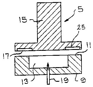
Figs. 1, 2 and 3 show one version of the thrust bearing of the
present invention. The thrust bearing 5 utilizes a bearing 9~ having a
sealing face 11 positioned adjacent a rotating member 15 having a
sealing surface 17. The bearing 9 and rotating member 15 are disposed
so that the sealing face 11 is positioned in spaced apart opposed
relationship with the sealing surface 17. A reservoir 13 is positioned in
the bearing 9 adjacent to the sealing face 11 on the bearing. A
passageway 19 extends through the bearing 19 and into communication
with the reservoir 13. The passageway 19 is used to supply a fluid or
lubricant to the reservoir 13. As shown in Figs. 1-3, the bearing 9 is
substantially cylindrical in shape and the reservoir 13 is also substantially
cylindrical in shape and positioned substantially in the center of the
bearing 9. The rotating member 15 is also substantially cylindrical and
the sealing surface 17 is substantially cylindrical in shape. The diameter
of the sealing surface 17 is substantially the same as the diameter of the
sealing face 11 on the bearing 9.
Positioned in the sealing surface 17 of the rotating member 15
are a plurality of recesses 25. Each recess 25 consists of a pocket 27
and a wedge-shaped chamber 31. The pockets 27 have a uniform depth
and extend radially outwardly from the center portion of the sealing
surface 17. The pockets can increase in width as they extend radially
outwardly on the sealing surface 17. An inner portion 29 of the pocket
27 that is closest to the center of the sealing surface 17 is disposed to
be over the fluid reservoir 13. This inner portion 29 of the pocket 27 is
positioned so that the inner portion 29 is in free communication with the
fluid reservoir 13. The pockets 27 end before they reach the outer
periphery of the sealing surface 17 of the rotating member 15.
CA 02285319 2006-03-09
8
Positioned adjacent and in communication with each pocket 27 is
a wedge-shaped chamber 31. The wedge-shaped chamber 31 extends
radially outwardly on the sealing surface 17 of the rotating member 15.
The wedge-shaped chambers 31 terminate adjacent the outer periphery
of the sealing surface 17 at substantially the same location as- the
pockets 27. The inner portion 33 of the wedge-shaped chambers 31
terminates at a radial location so that the wedge-shaped chambers 31 do
not overlap and are not in communication with the reservoir 13. The
wedge-shaped chambers 31 have a depth that varies across the width of
the chamber. The deepest portion of the wedge-shaped chambers 31 is
located adjacent the pocket 27. As the wedge-shaped chamber 31
moves away from the pocket 27 in a circumferencial direction, the depth
of the wedge-shaped chamber 31 decreases. The portion of the wedge-
shaped chamber 31 that is circumferencially spaced the furthest from the
pocket 27 essentially merges with the sealing surface 17 of the rotating
member 15. The wedge-shaped chambers 31 can increase in width as
they extend radially outwardly on the sealing surface 17.
Figs. 4 and 5 show another embodiment of the invention wherein
an annular reservoir 43 is positioned on a seating face 41 on a bearing
39. At least one passageway 49 is disposed for supplying fluid under
pressure to the annular reservoir 43. In practice, it has been found that
three equally spaced passageways 49 work particularly well in supplying
fluid under pressure to the annular reservoir 43. A flow passageway 51
extends through substantially the center of the bearing 39 to provide
fluid through the rotating member 15. The rotating member 15 has
substantially the same construction as the rotating member previously
described with respect to Figs. 1-3. An inner land 47 separates the
annular reservoir 43 from the flow passageway 51. The flow
passageway 51 can be, for example, a pump inlet passage or a turbine
outlet passage. The pocket 27 of the recess 25 on the rotating member
CA 02285319 2006-03-09
9
15 is positioned so that it is in communication with the annular reservoir
43. The wedge-shaped chamber 31 of the recess 25 is positioned so
that it is in communication with the pocket 27 but not in communication
with the annular reservoir 43. This is essentially the same positioning for
the recesses 25 as previously described with regard to rotating member
15.
Figs. 6-8 show another embodiment of the thrust bearing of the
present invention. In Fig. 6, the thrust bearing is used in a pump or
turbine and the axial thrust is generated by different pressures within the
casing of the pump or turbine. In this embodiment, pressurized fluid can
be drawn from a high pressure region 64 in the casing and used to
pressurize the bearing cavity. As the axial thrust imposed upon the rotor
of the pump or turbine is generated by the different pressures within the
casing, the high pressure that is utilized to pressure the reservoir of the
thrust bearing should always be sufficient to counteract the axial forces
on the rotor. Explained in a different manner, as the axial thrust on the
rotor increases due to increases in pressure in the casing, that same
increased pressure would be available for supply to the reservoir of the
thrust bearing and this effectively counteracts the axial thrust present in
the bearing cavity. In this high pressure region 64 in the pump casing
there is always sufficient pressure to supply fluid to an annular groove
73 of the thrust bearing. This is different than the diffuser section of a
pump where the pressure can drop due to the increase in fluid velocity
at run-out conditions. Thus, using the high pressure region 64 of the
pump prevents reverse flow problems and thrust bearing failure.
The centrifugal pump 57 shown in Fig. 6 has a pump casing 59 and
a bearing housing 61 that encloses a rotating impeller 63. The rotating
impeller 63 is mounted on a shaft 65. The shaft 65 is supported on a
bearing 67 that radially positions the shaft but does not resist axial
forces. A thrust bearing 71 is located in a counterbore of the pump
CA 02285319 2006-03-09
c
casing 59. The thrust bearing 71 has an annular reservoir 73 as
previously described with regard to Figs. 4 and 5. The face 77 of the
rotating impeller 63 has a plurality of recesses 79 that are formed of ,
pockets 81 and wedge-shaped chambers 83. The recesses 79 and the
5 annular reservoir 73 are shown in more detail in Figs. 7 and 8~: The
annular reservoir 73 of the recesses 79 have the same construction and
orientation as shown in Figs. 4 and 5.
The thrust bearing 71 has at least one passageway 87 that
extends from the annular reservoir 73, through the thrust bearing 71 to
10 the impeller discharge region 64 in the pump casing 59. The discharge
region 64 provides a source of high pressure fluid to the annular reservoir
73. In practice, it has been found advantageous to have three equally
spaced passageways 87 positioned in the bearing 71 to supply fluid
under pressure to the annular reservoir 73. A pin 88 can be disposed to
extend from the thrust bearing 71 into the pump casing 59 to prevent the
thrust bearing from rotating in the pump casing as the impeller 63 is
rotated.
Another embodiment of the invention is shown in Fig. 9. This
embodiment is very similar to the centrifugal pump 57 shown in Fig. 6-8
with the exception that a second thrust bearing 71' is positioned in the
bearing housing 61 adjacent to the rotating impeller 63. The thrust
bearing 71' has an annular reservoir 73'. It is substantially the same as
the thrust bearing as described with regard to Fig. 6-8. A plurality of
recesses, the same as the recesses 79 shown in Fig. 8, are positioned on
a second face 77' of the impeller 63 that faces the second thrust bearing
71'. The recesses are as previously described with regard to Fig. 7. The
embodiment shown in Fig. 9 allows the centrifugal pump to counteract
axial thrust that are directed in both directions along the axis of the shaft
65.
CA 02285319 2006-03-09
The operation of the invention will be best understood by referring
to Fig. 6-8 that show the use of the thrust bearing concept with a
centrifugal pump 57. In this embodiment, a liquid is drawn into the pump
inlet 60 by the rotation of the impeller 63. The rotating impeller causes
the fluid to move outwardly in the pump casing 59 to the iiischarge
passageway 89. As the fluid is forced radially outwardly by the rotation
of the impeller 63, the pressure of the liquid is increased. As the impeller
63 rotates, the total pressure forces on the back shroud of the impeller
63 are of a greater magnitude than the pressure force on the front shroud
face 77. This pressure imbalance causes the impeller 63 to move in a
direction toward the pump inlet 60. This motion of the rotating impeller
63 creates an axial thrust along the axis of shaft 65 upon which the
impeller 63 is mounted. The bearing 67 in the bearing housing 61
supports the shaft 65 but does not prevent axial movement of the shaft
65 in a direction that is parallel to the axis of the shaft. It is important
that the rotating impeller 63 not strike the thrust bearing 71 as it moves
in a direction toward the pump inlet 60.
To counteract the axial thrust on the rotating impeller 63, fluid
from the impeller discharge region 64 of the centrifugal pump 57 is
supplied through three equally spaced passageways 87 in the thnrst bearing
7i to the annular reservoir 73 located in the thrust bearing 71. The
pressure of the fluid that is positioned in the annular reservoir 73 acts
against the rotating impeller 63 and assists in maintaining the impeller in
a spaced apart relationship from the thrust bearing 7~1. in addition, the
fluid that is supplied to the annular reservoir 73 is also in communication
with the pockets 81 of the recesses 79 located on the face 77 of the
impeller 63. Thus, some of the fluid under pressure in the annular
reservoir 73 moves into the pockets 81 and also into the wedge-shaped
chambers B3 that are connected to the pockets 81. The rotation of the
impeller 63 causes the liquid that is in the pockets 81 to move in a
CA 02285319 2006-03-09
12
circular or circumferential motion. The rotation of the.impeller 63 also
causes the liquid in the pockets 81 to move radially outwardly in the
pockets as the impeller rotates. The radially outwardly motion of the
fluid causes the pressure to rise through centrifugal force in each pocket
81. The pressure in the pockets 81 continually increases as~ the ~~luid
moves further radially outwardly in the pockets 81. The fluid that is in
the wedge-shaped chambers 83 that are in communication with the
pockets 81 also experiences the same centrifugal force and an increase
in pressure as the liquid in the wedge-shaped chambers 83 moves radially
- outwardly. The tluid pressure that is generated in the pockets 81 and
wedge-shaped chambers 83, due to the rotation of the impeller 63,
generates a fluid pressure that is greater than the fluid pressure present
in the annular reservoir 73. This fluid pressure is exerted between the
rotating impeller 63 and the face 75 of the thrust bearing 71. This fluid
pressure in the pockets 81 and wedge-shaped chambers 83 counteracts
the axial forces acting on the impeller 63 that moves the impeller 63 in
a direction towards the pump inlet 60.
The wedge-shaped chambers 83 also act to generate an additional
pressure gradient to balance the axial thrust on the rotating impeller 63.
The rotation of the impeller 63 drags fluid in the direction of rotation. As
the wedge-shaped chambers 83 decrease in depth as they move away
from the pockets 81, there is a decreasing clearance between the wedge-
shaped chambers 83 and the face 75 of the thrust bearing 71.
Accordingly, the pressure in the wedge-shaped chambers 83 increases
as the fluid moves circumferencially from the portion of the wedge-
shaped chamber 83 that is located adjacent to the pockets 81 to the end
of the wedge-shaped chamber 83 that is spaced apart from the pockets
81. It should be noted that the wedge-shaped chambers 83 are
positioned so that the rotation of the impeller 63 drags the fluid in the
wedge-shaped chambers in this direction. The decrease in clearance
CA 02285319 2006-03-09
a
13
between the wedge-shaped chambers 83 and the face. 75 of the thrust
bearing 71 generates an increase in pressure that acts against the
impeller 63 to offset the axial thrust acting on the impeller.
Since the liquid under pressure is supplied to the annular reservoir
73, this liquid can escape between the face 75 of the thrust bearing 71
and the face 77 of the impeller 63. If there is a large spacing between
the face 77 of the impeller 63 and the face 75 of the thrust bearing 71,
the liquid in the annular reservoir 73 will move out into the discharge and
suction region of the pump casing 59. However, as the face 77 of the
impeller 63 moves toward the face 75 of the thrust bearing 71 there is
less opportunity for the liquid to flow between the thrust bearing 71 and
the impeller 63 into the discharge and suction region of the pump casing
59. In fact, as the impeller 63 gets closer to the thrust bearing 71 more
fluid will be retained in the annular reservoir 73 and the hydrostatic
pressure in the reservoir 73 will increase. More liquid will also be
retained in the pockets 81 and wedge-shaped chambers 83 and the
pressure generated by the centrifugal force of the rotating impeller 63
will cause an increase in the pressure in the recesses 79 as the liquid
moves radially outwardly in the recesses. In addition, the space between
the wedge-shaped chambers 83 and the face 75 of the thrust bearing 71
will be reduced and this will increase the pressure in the wedge-shaped
chambers 83 due to the hydrodynamic effect created by the wedge-
shaped configuration of these chambers. This establishes that the thrust
bearing of the present invention utilizes three methods to resist the axial
force present on the rotating impeller 63, that is, the pressure generated
in the recesses 79 by the centrifugal force supplied by the rotating
impeller, the pressure created by the hydrodynamic effect of the wedge-
shaped chambers, and the hydrostatic pressure present in the annular
reservoir 73. All three pressures act upon the impeller 63 to keep the
impeller 63 spaced apart from the face 75 of the thrust bearing 71.
CA 02285319 2006-03-09
14
Since the pressure that acts upon the impeller 63 varies with the
clearance between the impeller 63 and the thrust bearing 71, the thrust
bearing 71 can accommodate changes in operating conditions for the .
centrifugal pump. If the pump rotates faster and there is a larger axial
thrust applied to the impeller 63, the space between the impeller 63-arid
the thrust bearing 71 decreases which results in an increase in the
effective pressure provided by the fluid that is supplied to the annular
reservoir 73. The pressure that is provided by the fluid supplied to the
annular reservoir 73 will continue to increase until the pressure acting on
the impeller 63 balances the axial thrust experienced by the impeller 63.
As the impeller 63 moves away from the thrust bearing 71, the effect of
the pressure of the liquid supplied to the annular reservoir 73 will
decrease and the impeller 63 w111 be allowed to move toward the thrust
bearing 71 until the axial thrust forces on the impeller 63 are balanced
out.
Since the pressurized fluid is drawn from the impeller discharge
region 64 of the centrifugal pump 57, there should always be sufficient
pressure available in the liquid that is supplied to the annular reservoir 73
to counteract axial thrust forces that are imparted to the rotating impeller
63. Since the axial thrust on the impeller 63 is generated by differential
pressures within the pump casing 59 of the centrifugal pump 57, the
high pressure liquid in the impeller discharge region 89 should always
have sufficient pressure to counteract the axial thrust forces that are
generated by the pressure differentials.
It has been found that sufficient pressure exists at the impeller
discharge thrust bearing outer diameter for all capacities from zero flow
to run out to reliably operate the thrust bearing of this invention. It
should be noted that the combination of hydrostatic and hydrodynamic
operation offers advantages that cannot be achieved when either method
is used individually. For instance, the hydrostatic feature prevents
CA 02285319 2006-03-09
contact between the thrust bearing and impeller during. the time where
the impeller speed is vamping up to an RPM where the hydrodynamic
pressure become effective. Starting and stopping of a pump is usually
the time of greatest wear on bearing. The hydrostatic feature minimized
5 this wear.
As mentioned previously, pump impellers that have a ratio
between the impeller outside diameter and wear ring diameter of less
than 1.5 cannot incorporate sufficient hydrostatic annular groove area to
effectively counterbalance opposing thrust loads of the impeller. With
10 the present invention, the hydrodynamic feature provides the additional
counterbalancing pressure necessary for reliable operation.
Fig. 9 shows an embodiment where a thrust bearing 71 is
positioned on each side of the rotating impeller 63. This embodiment
functions in exactly the same manner as the embodiment described in
15 Figs. 6-8. The only difference is that there is a self-regulating thrust
bearing located on each side of the rotating impeller 63 and this allows
the thrust bearings 73 to counteract axial thrust forces that are imparted
to the impeller in a direction toward the pump inlet 60 or away from the
pump inlet 60.
Figs. 10-13 show another embodiment of a thrust bearing.
This embodiment is similar to the embodiments previously disclosed
but this embodiment works particularly welt with a hydraulic turbo-
charger as shown in U.S. Patent Nos. 4,966,708; 4,983,305 and
5,049,045. Hydraulic turbochargers are usually positioned downstream
of a feed pump and there is a large axial thrust imposed on the rotor
of the turbocharger before there is sufficient hydraulic energy available
in the turbine section to rotate the turbine impeller. A hydrostatic
thrust bearing that is pressurized from either the pump section of the
turbocharger on the inlet pipe to the turbine nozzle could accommodate
CA 02285319 2006-03-09
16
the axial thrust and allow the turbine rotor to rotate. However, there are
several significant drawbacks to such a hydrostatic thrust bearing. The
external pressurization line and fittings that are required are usually made
of stainless steel and costly to produce. Any failure of the external
pressurization line results in an interruption of pressurized fluid to the
thrust bearing and a failure of the thrust bearing to accommodate axial
. thrust loads. Obviously, a failure of the thrust bearing to work properly
results in a failure of the turbocharger. For a hydraulic turbocharger a
purely hydrodynamic thrust bearing will not work because the axial force
on the turbine impeller is of such a magnitude that the rotor cannot
develop sufficient breakout torque to start rotation.
A distinct improvement in hydraulic turbocharger thrust bearings
can be made by combining hydrostatic and hydrodynamic features into
a thrust bearing. However, the hydrodynamic features of the thrust
bearing must be tailored to not create a pumping action that decreases
the efficiency of the hydraulic turbocharger.
The thrust bearing shown in Figs. 10-13 is similar to the previously
described thrust bearings. A thrust bearing 115 is positioned adjacent
the turbine impeller 105 in the turbine casing 107. The turbine impeller
105 has a sealing surface 111. The bearing 115 is positioned in the
bearing housing 117 adjacent to the turbine impeller 105. The bearing
115 has a sealing face 119 that is positioned in spaced apart opposed
relationship to the sealing surface 111 on the turbine impeller 105. A pin
121 extends from the bearing housing 117 in to the bearing 115 to
prevent the bearing from rotating.
An annular groove or fluid reservoir 123 is positioned in the sealing
face 119 of the bearing 115. At feast one passageway 125 connects the
annular groove 123 to a region or volute 129 that is positioned in the
turbine casing 107 adjacent to the outer periphery of the turbine impeller
105.
CA 02285319 2006-03-09
17
A plurality of recesses 131 are positioned in the sealing face 119
of the bearing 115. Each recess 13i has a pocket 133 and a wedge
shaped chamber i 35. The recesses, pockets and wedge shaped
chambers are generally constructed as previously described. However,
the pockets and wedge shaped chambers are positioned in the sealing
face of the bearing 115 instead of the rotating member or impeller as
previously described. Also, the pockets 133 are in direct communication
with the annular groove 123 positioned in the sealing face 119 of the
bearing 115.
In operation, pressurized fluid is introduced into the volute 129 in
the turbine casing 107. This fluid under pressure acts upon the turbine
impeller 105 and causes the impeller 105 to rotate. The fluid also enters
the passageway 125 and is accordingly supplied to the annular groove
123, the pockets 133 and the wedge shaped chambers 135 in the
bearing 115. The hydrostatic area, that is the area of the annular groove
123 and the recesses 131, provides enough fluid pressure on the turbine
impeller 105 to overcome breakout torque and to allow the turbine
impeller to rotate. As the turbine impeller 105 rotates, the fluid supplied
to the recesses 131 is dragged in the direction of rotation. The fluid
pressure increases as the fluid is squeezed by the decreasing clearance
in the wedge shaped chambers 135. This provides a hydrodynamic
pressure balancing force to the counterbalance axial thrust loads on the
turbine impeller 105. The fluid pressure increases in the wedge shaped
chambers 135 due to increasing rotational speed of the turbine impeller,
decreasing clearance between the sealing surface 111 of the turbine
impeller and the seating face 119 on the bearing 115 and with increasing
viscosity of the fluid supplied to the volute 129.
The fluid introduced into the volute 129 to cause the turbine
impeller 105 to rotate is discharged from the turbine 104 at the center
106 or eye region of the turbine impeller 105. By placing the recesses
CA 02285319 2006-03-09
s
18
131 on the sealing face 119 of the bearing 115 a hydrodynamic pressure
is generated to counteract axial forces of the impeller turbine 105.
However, since the recesses 131 are not rotating, there is no pumping
action that causes the fluid to move in a radially outwardly direction.
The elimination of the pumping action increases the efficiency o~ the
turbine 104. tf fluid is pumped radially outwardly by the pumping action
of rotating recesses located on the turbine impeller 105, this fluid
pressure is throttled down to the pressure level existing in the volute 129
and is therefore lost to do useful work and results in decreased
efficiency. By placing the recesses 131 on the non-rotating sealing face
119 of the bearing 115 a hydrodynamic axial thrust balancing force can
be generated for the thrust bearing 103 without significantly reducing the
efficiency of the turbine 104.
It is to be understood that a further thrust bearing can be
positioned on each side of the rotating impeller 105. This embodiment
functions in exactly the same manner as the embodiment described in
Fig. 9 in that there is a self-regulating thrust bearing located on each side
of the rotating impeller which allows the thrust bearings to counteract
axial thrust forces that are imparted to the impeller in a direction toward
the volute 129 or away from the volute 129.
The above detailed description of the present invention is given for
explanatory purposes. It will be apparent to those skilled in the art that
numerous changes and modifications can be made without departing
from the scope of the invention. Accordingly, the whole of the foregoing
description is to be construed in an illustrative and not a limitative sense,
the scope of the invention being defined solely by the appended claims.