Note : Les descriptions sont présentées dans la langue officielle dans laquelle elles ont été soumises.
CA 02285615 1999-10-04
WO 98/45168 PCT/SE98/00610
1
TITLE:
Motorized vehicle
TECHNICAL FIELD:
The present invention relates to a motorized vehicle for
travel on soft ground surfaces, such as snow, according to
the preamble of the appended claim 1.
BACKGROUND OF THE INVENTION:
One problem associated with vehicles for travel on soft
ground surfaces, such as snow, is to provide sufficient
traction to propel the vehicle even if the surface is very
loose, ie. it cannot support large surface pressures
without giving in and collapsing.
On known vehicles of the snowmobile type, generally, two
steerable front skis are provided together with a rear
mounted and suspended drive belt. The vehicle is pressed
down into the ground surface by its own heavy weight in
order to provide any traction, resting upon the front skis
and the drive belt. Thus, if the ground surface is suffi-
ciently soft, the snowmobile will risk sinking too deeply
into the surface and it may become stuck. A vehicle of this
type is disclosed in US Patent 4,133,400 (Shiraishi).
Other known motorized vehicles for utilization on snow
surfaces, or similar, are of the type having one steerable
front ski together with a rear mounted and suspended drive
belt. The full weight of the vehicle rests on the ski and
drive belt, comparable to a snowmobile mentioned above.
w ~5 These vehicles are usually of lighter weight than the
snowmobile type, but, because of their lighter and smaller
construction, lack the relatively large belt drive surface
area of the snowmobile . This impedes their traction on soft
ground surfaces. Known vehicles of this type are disclosed
in the US Patents 4,613,006 (Moss et al.), 4,307,788
CA 02285615 1999-10-04
WO 98145168 PCT/SE98/00610
2
(Shelton), 4,286,682 (Stewart et al.) and 4,244,436 (Condon
et al.).
Other motorized vehicle types for utilization on snow
surfaces, or similar, are of the variety where a tradi- '
tional skiboard has been equipped with a motorized drive
belt having some type of drive profiles arranged
perpendicularly to the direction of travel and protruding
some distance into the snow. This drive belt is not sus-
pended and has its drive surface substantially level with
the gliding surface of the skiboard, to also enable tradi-
tional downhill skiing with this type of skiboard, because
the drive profiles can be folded back to a position flush
with the drive belt. This results in a vehicle having
sufficient traction for motorized travel only on relatively
hard packed snow or similar. Vehicles of this type are
disclosed in the US Patent 4,984,648 (Strzok) and in the
French Patent Application 2 688 701 (Martinez).
Still a further vehicle type claimed to be utilizable on
soft ground surfaces consists of a motorized trackboard
having propelled tracks on each side of a main body
portion. This type of vehicle rests solely on its tracks
during use. A preferred embodiment has a front and a rear
belt pair, where the rear pair is motorized and the front
pair is made steerable. A vehicle of this type is disclosed
in US Patent 5, 305, 846 (Martin) . Vehicles like these, which
rely on tracks for all its ground surface contact, require
relatively large and heavy belts resulting in vehicles
having a large total weight. Thus, if the ground surface is
sufficiently soft, the vehicle will sink too deeply into
the surface and lose all traction (compare snowmobile type
vehicles above).
CA 02285615 1999-10-04
WO 98145168 PCT/SE98/00610
3
SUMMARY OF THE INVENTION:
The object of the present invention is to provide a vehicle
which has improved traction on soft ground surfaces, such
as snow, combined with a mechanically simple construction
to keep manufacturing costs low.
Said object is achieved by the arrangement according to the
present invention, whose features are detailed in appended
claim 1.
Preferred embodiments of the present invention are detailed
in the dependent claims.
t
a
1
CA 02285615 1999-10-04
WO 98!45168 PCT/SE98/00610
4
BRIEF DESCRIPTION OF THE DRAWINGS:
The invention will be described in greater detail in the
following with reference to the accompanying drawings, in '
which
Fig. 1 is a partially sectioned elevational view of a
vehicle according to the present invention,
Fig. 2 is a partially sectioned plan view of a vehicle
according to the invention, whilst
Fig. 3 shows a view from below of a vehicle according to
the invention.
PREFERRED EMBODIMENTS:
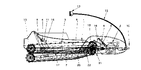
Figs. 1 and 2 show a motorized vehicle having a body unit
1 in which a propulsion unit 2 is carried. Any known power
source which is light and powerful enough can be used as a
propulsion unit, e.g. small i.c. engines, electric motors
- or similar. Speed regulation of the propulsion unit 2 is
accomplished via a hand-held throttle device 13. The
I throttle device 13 is rigidly attached to a front part of
the vehicle by a combined throttle cable/support hose 15,
thus enabling the driver to hold onto the throttle device
13, by pulling backwards, which enhances the driver's
balance.
As is shown in Fig. 3, the body unit 1 comprises gliding
surfaces 5 arranged on the bottom of the body unit, ie.
facing the ground. The gliding surfaces are preferably
covered with some type of coating which enhances the
sliding properties of the gliding surfaces by lowering the
friction between the gliding surfaces and the soft ground ,
surf aces .
CA 02285615 1999-10-04
WO 98/45168 PCT/SE98/00610
The propulsion unit 2 is connected to a drive unit 3 which
is held and guided by a suspension unit 4. The drive unit
3 comprises an endless belt 6 having a traction surface 7
facing the soft ground surface. The total surface area of
5 the gliding surfaces 5 constitutes approximately 50 ~ or
more of the total vehicle-to-ground surface (ie. the sum of
the gliding surfaces 5 and the traction surface 7). The
relatively large gliding surfaces 5 make it possible to use
lower output engines, and thus smaller, quieter and less
polluting engines. The endless belt rotates over a forward
driving roller 18 and a rearward roller 19 whilst gliding
on a slide frame 20. This slide frame 20 may have gliding
strips arranged between it and the endless belt to lower
friction.
The endless belt 6 may comprise standard profile snowmobile
belts, i.e. no special demands are placed on the construc-
tion of the belt because the vehicle of the invention has
a relatively low total weight. The endless belt 6 may have
a typical width of approximately 230 mm. Similarly to a
snowmobile construction, the endless belt 6 can be
lubricated by the snow when the vehicle is used on snowy
ground surfaces.
The propulsion unit 2 may advantageously be equipped with
sealing discs arranged on both sides of the propulsion unit
on its drive shafts, to prevent the ingress of snow, or
other lose material, into the engine compartment inside the
body unit 1 as the snow is thrown from the drive belt 6.
The endless belt traction surface 7 has a forward part 22
and a rearward part I7, where the forward part is angled
upwards in the travel direction of the vehicle so that
loose ground material, eg. snow, is packed under the
forward part. The rearward part 17 is substantially
parallel to the ground surface and is held in a lower
CA 02285615 1999-10-04
WO 98/45168 PCT/SE98/00610
6
position than the forward part 22, i.e. it sinks lower into
the soft ground material. The rearward part 17 is longer
relative to the forward part 22. The traction surface 7 may '
have a length which corresponds to approximately 2/3 of the
total length of the vehicle, which typically may be around
1700 mm.
The suspension unit 4 comprises automatic height adjusting
means 8, 9, 16 for adjusting the position of the drive unit
3 relative to the body unit 1. The automatic height
adjustment means 8, 9, 16 comprise forward and rearward
automatic height adjustment means.
In a preferred embodiment, the suspension unit 4 comprises
front and rear dampers 8, advantageously of the gas-filled
type, affixed at one end of each damper to mounting struts
16 and at another end to the body unit 1. The dampers at
all times (except when the drive unit 3 is in a retracted
transport position) press the drive unit into the soft
ground surfaces in order to achieve good traction. The gas-
filled dampers 8 thus regulate the height of the endless
belt 6, relative to a length axle 10 of the vehicle,
according to the softness of the ground surfaces. One,
possibly two or more, dampers may be used in each of the
front and rear positions. Also gas-filled dampers of the
adjustable type may be used.
The suspension unit 4 further comprises parallel link arms
9 which are arranged so that the movement of the suspension
unit 4 is limited to one plane perpendicular to the general
plane of the soft ground surfaces. The parallel link arms
9 may be attached to each other via a bridge 23. The front
damper's mounting strut is affixed to the parallel link
arms 9 and the rear damper's mounting strut is affixed to
the drive unit 3. The gas-filled dampers 8 may be mounted
in a plurality of mounting holes 11, or similar, arranged
CA 02285615 1999-10-04
WO 98/45168 PCT/SE98/00610
7
on the mounting struts 16, in order to make it possible to
change the geometry of the drive unit/suspension unit
assembly for achieving the desired turning properties of
the vehicle. Factors to consider in this context are, for
example, the weight of the driver and the ground
conditions.
The gliding surfaces 5 advantageously extend on both sides
of the endless drive belt 6 to enhance the turning
capabilities of the vehicle according to the invention. The
drive belt 6 is thus limited to a relative movement
essentially perpendicular to a general plane of the gliding
surfaces 5, which contributes to the good traction
properties of the vehicle.
The driver stands or sits on the body unit 1 which also may
comprise foot ledges 12 on which the driver's feet can
rest. These ledges may advantageously be equipped with some
type of friction surface to enhance grip, e.g. angular
profiles of aluminium or similar having a friction-enhanc-
ing pattern on the surface. The ledges also strengthen the
body unit 1 construction. It is also possible ~co provide
some type of foot straps on these foot ledges 12 to further,
increase grip.
The dampening/downwards pressing effect of the gas-filled
dampers 8 is essential to make it possible to turn the
vehicle since it does not have any steering means as such.
Turning is accomplished by shifting the driver's body
weight from side to side, and possibly from fore to aft and
vice versa. To further facilitate turning, small cutoffs 14
may be incorporated into the outer and rearmost portion of
the gliding surfaces 5. '"
The whole suspension unit 4/driving unit 3 assembly may be
arranged to be foldable into a stowage position where the
CA 02285615 1999-10-04
WO 98J45168 PCTJSE98I00610
8
traction surface 7 of the endless belt 6 is situated
completely inside the lower edge 21 of the body unit 1,
thus enabling the vehicle to glide freely on the ground
surface. This can be used, for example, to glide down hills
without the need for added propulsion. Typically, the
suspension unit 4/driving unit 3 assembly may be located
30-50 mm above the lower edge of the body unit 1 in this
stowage position, compared to a maximum downward position
of typically 150-200 mm at the rear roller 19 and 50-100 mm
below the lower edge 21 of the body unit 1 at the forward
roller 18. The suspension unit 4/driving unit 3 assembly
may also advantageously be in the stowage position during
transportation of the vehicle, eg. on or in a car.
A handle may be affixed to the front of the body unit to
facilitate the carrying or dragging of the vehicle and also
to double as a collision bumper. Splash guards may also be
arranged on the back of the body unit 1.
A small sleigh can be pulled by the vehicle, this sleigh
may also be used to store the vehicle during transport. Any
snow remaining on the vehicle would then run down into the
sleigh if and when the snow would melt.
The operational range of the vehicle according to the
invention depends i.a. on the propulsion unit and the size
of its fuel reservoir, but is generally shorter than that
of a traditional snowmobile, typically 20-50 km compared to
150 km. The total weight of the vehicle according to the
invention may be approximately 30-50 kg compared to more
than 200 kg for a traditional snowmobile. It is thus .
possible for one person to lift the vehicle up onto a cart
or similar. The turning radius of the vehicle is also .
smaller than that of a traditional snowmobile. The vehicle
according to the invention is thus smaller and lighter than
a traditional snowmobile, which means it should cause lower
CA 02285615 1999-10-04
WO 98/45168 PCT/5E98/00610
9
wear and tear to the environment in which it is used. It
also utilises smaller and therefore quieter and less fuel
consuming engines, possibly also electric motors. The lower
weight combined with the gliding surfaces makes the vehicle
according to the invention very suitable for soft and deep
snow conditions, conditions which are extremely unsuitable
for traditional snowmobiles. The vehicle has an approximate
bearing surface towards the ground of 0.85 m' which
translates into a pressure of approximately 1.4 kg/dmz
(including a person weighing 80 kg). A normal snowmobile
weighing 225 kg and having a bearing surface of 0.75 m2
causes a pressure of 4.1 kg/dmz (including a person
weighing 80 kg). The same person on a pair of normal skis
has a pressure towards the ground of approximately 2.9
kg/dm2. The low weight of the vehicle according to the
invention combined with the small dimensions also facili-
tates storage of the vehicle.
The invention is not limited to the description above nor
to the examples shown on the drawings, but may be varied
within the scope of the appended claims. For example, a
possible alternative to gas-filled dampers are standard
springs and shocks, but these are generally heavier and
provide a bouncy ride which might not be desirable.
Advantageously, the propulsion unit is connected to the
drive unit via a variator drive because this provides the
smoothest running characteristics of the vehicle, but a
cheaper alternative is an ordinary centrifugal clutch
although it may provide a jerkier power transmission.