Note : Les descriptions sont présentées dans la langue officielle dans laquelle elles ont été soumises.
CA 02285742 2004-04-28
PRESSURE CASTING OF BATTERY TERMINALS
FIELD OF THE INVENTION
This invention relates generally to pressure casting of lead articles such
as battery terminals.
BACKGROUND OF THE INVENTION
Battery terminals are a typical type of part that is made of lead or a lead
alloy and are usually cold formed in order to produce a battery terminal that
is free of
voids and cracks. If lead or lead alloy battery terminals are pressure cast,
air is left in
the battery terminal cavity in the mold so that as the lead solidifies, the
air bubbles
io prevent the battery terminal from cracking. That is, the air bubbles act as
fillers so the
lead remains distributed in a relatively uniform manner throughout the battery
terminal. Unfortunately, if air bubbles that form within the battery terminal
are too
large or numerous it can cause the battery terminal to be rejected. In order
to
minimize the formation air bubbles in a battery terminal, a vacuum can be
drawn in
is the battery terminal cavity mold. The vacuum removes air from the mold and
inhibits
the forming of air bubbles in the battery terminal, but the battery terminals
cast using a
vacuum in the battery terminal cavity oftentimes solidify in an uneven manner
producing battery terminals with cracks or tears which makes the batters
terminals
unacceptable for use.
20 SUMMARY OF THE INVENTION
According to one aspect of the present invention there is provided a
method of forming a pressure cast battery part free of cracks and voids
comprising
the steps of:
introducing a molten lead under pressure to a battery part cavity
25 including a runner receiving the molten lead therethrough;
sealing off the runner; and
la
CA 02285742 2004-04-28
increasing the pressure of the lead in the battery part cavity.
According to a further aspect of the present invention there is provided a
system for pressure casting of a battery terminal to inhibit formation of
cracks and
tears in the pressure cast battery terminal comprising:
a source of pressurized molten lead;
a mold, said mold having a battery terminal cavity therein, said mold
further having a runner for supplying the molten lead to said battery terminal
cavity;
a vacuum source, said vacuum source connected to said battery
terminal cavity to enable said vacuum source to evacuate the air from said
battery
lo terminal cavity prior to supplying molten lead to said battery terminal
cavity;
a pressure sensor, said pressure sensor mounted in said mold to
monitor the pressure of the lead as the molten lead is supplied to said
battery terminal
cavity;
a pressure responsive piston located in a hot spot of the mold, said
pressure responsive piston movable into said mold to decrease the volume of
the
cavity in response to pressure within the mold indicating a particular phase
of the lead
to thereby produce a pressure cast battery terminal substantially free of
cracks and
tears.
According to a further aspect of the present invention there is provided a
system for molding lead articles under pressure comprising:
a source of pressurizeable molten lead;
a mold having a mold cavity therein, said mold maintainable at
sufficiently low temperature so that a charge of molten lead located in said
mold cavity
solidifies to thereby form a solidified casting in said mold cavity;
a housing having a runner, said runner connecting said mold cavity to
said source of pressurizeable molten lead, said runner maintainable at
sufficiently
lb
CA 02285742 2004-04-28
high temperature to maintain said molten lead in a molten state so that the
mold
cavity can be refilled with a fresh charge of molten lead when a solidified
casting is
removed therefrom; and
a shut-off valve, said shut-off valve having an open position for allowing
the charge of molten lead to flow into said mold cavity and a closed position
to
prevent molten lead from flowing out of said runner as the molten lead in said
cavity
solidifies.
According to a further aspect of the present invention there is provided a
method of pressure casting a lead battery terminal to inhibit the formation of
cracks
io and tears in the battery terminal comprising the steps of:
evacuating a battery terminal cavity to remove air therefrom;
injecting molten lead under pressure into the battery terminal cavity; and
reducing the volume of the battery terminal cavity while the molten lead
is in a liquid-to-solid transformation stage to cause the molten lead to flow
into the
is reduced volume before the molten lead solidifies.
According to a further aspect of the present invention there is provided a
method of pressure casting a lead article comprising the steps of:
increasing the pressure of a source of molten lead sufficiently to force
the molten lead to flow in a liquid state into a mold cavity;
20 maintaining the mold cavity at a sufficiently low temperature so that
when molten lead is injected therein the molten lead solidifies therein;
closing a runner to said mold cavity while maintaining said molten lead
in the runner in a closed system to prevent entrapment of air in the molten
lead in the
runner as a fresh charge of molten lead is introduced into the closed system;
and
25 removing a solidified casting from said mold cavity.
According to a further aspect of the present invention there is provided a
lc
CA 02285742 2004-04-28
system for molding metal articles, the system comprising:
means for maintaining the system in a closed condition to prevent air
from entering the molten metal comprising:
a source of pressurizeable molten metal;
a mold having a mold cavity therein, said mold maintainable at
sufficiently low temperature so that a charge of molten metal located in said
mold
cavity solidifies to thereby form a solidified casting in said mold cavity;
a housing having a runner for flow of molten metal therethrough, said
runner connecting said mold cavity to said source of pressurizeable molten
metal,
io said runner maintainable at sufficiently high temperature to continuously
maintain said
molten metal in a molten state so that the mold cavity can be refilled with a
fresh
charge of molten metal from the runner when a solidified casting is removed
therefrom; and
a shut-off valve, said shut-off valve having an open position for allowing
molten metal to flow into said mold cavity, a closed position to prevent
molten metal
from flowing out of said runner as the molten metal in said cavity solidifies
and an
intensification position to increase the pressure in the mold cavity to
thereby minimize
shrinkage and voids in the casting.
According to a further aspect of the present invention there is provided a
system for pressure casting and at least partially cold forming a battery part
free of
cracks and tears comprising:
a source of pressurized molten lead;
a mold, said mold having a battery part cavity therein with a portion of
the mold having a surface defining a battery part electrical contact surface
and a
further portion of the mold defining a battery part non-electrical contact
surface;
a source of pressurized lead for filling the battery part cavity with molten
ld
CA 02285742 2004-04-28
lead; and
a piston, said piston having a surface positioned proximate the portion of
the battery part cavity defining a non-electrical contact surface for the
molten lead to
flow and solidify thereagainst to thereby produce a solidified battery part
that can
contain cracks and tears, said piston movable toward said solidified battery
part to
decrease the volume of the cavity and thereby cold form the battery part into
a
condition free of cracks and tears.
According to a further aspect of the present invention there is provided a
method for pressure casting and partial cold forming a battery part free of
cracks and
io tears comprising:
forming a mold with a battery part cavity having a non-electrical contact
surface and an electrical contact surface;
placing a piston having an end surface proximate the battery part cavity;
injecting lead under pressure into the battery part cavity;
allowing the lead to solidify therein to produce a solidified battery part
that can contain cracks and tears; and
driving the piston toward the solidified battery part with sufficient force
so as to mechanically deform at least a portion of the solidified battery part
to thereby
remove any cracks or tears from the solidified battery part.
According to a further aspect of the present invention there is provided
an apparatus for forming a two piece battery part comprising;
a mold having a battery part cavity therein;
a retractable member for supporting a core within the battery part cavity
while molten lead solidifies around the core to form a battery part; and
a piston, said piston being located in said mold and being driveable
toward said battery part cavity to simultaneously reduce the volume of the
battery
le
CA 02285742 2006-08-21
cavity and deform at least a portion of a solidified battery part therein.
According to a further aspect of the present invention there is provided a
method of forming a pressure cast battery part free of cracks and voids
comprising
the steps of;
s introducing a molten lead under pressure to a battery part cavity;
sealing off the battery part cavity while the battery part cavity contains
molten lead to thereby form a closed volume for the molten lead; and
increasing the pressure of the molten lead in the battery part cavity.
According to a further aspect of the invention there is provided a system
i o for pressure casting of a battery terminal to inhibit formation of cracks
and tears in the
pressure cast battery terminal comprising;
a source of pressurizable molten lead;
a mold, said mold having a battery terminal cavity therein;
a runner connecting said mold cavity to said source of pressurizeable
is molten lead for supplying the molten lead to said battery terminal cavity;
a vacuum source, said vacuum source connected to said battery
terminal cavity to enable said vacuum source to evacuate the air from said
battery
tenrinal cavity prior to supplying molten lead to said battery terminal
cavity;
a pressure sensor, said pressure sensor mounted in said mold to
2o monitor the pressure of the lead as the molten lead is supplied to said
battery terminal
cavity; and
a pressure responsive piston located in a hot spot of the mold, said
pressure responsive piston movable into said mold to decrease the volume of
the
cavity in response to pressure within the mold indicating a particular phase
of the lead
25 to thereby produce a pressure cast battery terminal substantially free of
cracks and
tears.
if
CA 02285742 2006-08-21
One embodiment of the present invenbon comprises a system for
molding lead articles wherein the system is maintained in a closed condition
to
prevent air from entering the molten lead in the system. The system includes a
mold
having a mold cavity with the mold maintainable at sufficiently low
temperature so that
a charge of molten lead located in the mold cavity solidifies to thereby form
a solidified
casting in the mold cavity. A housing having a runner for the flow of molten
lead
therethraugh connects the mold cavity to a source of pressurizeable molten
lead with
the runner maintainable at a sufficientiy high temperature so as to
continuously
maintain the molten lead in a molten state so that the mold cavity can be
refilled with
io a fresh charge of molten lead from the runner when a solidified casting is
removed
from the mold cavity. The system includes a shut-off valve, having an open
position
for allowing molten lead to flow into the moid cavity and a closed position to
prevent
molten lead from flowing out of the runner as the molten lead in the cavity
solidifies,
and if needed an intensification mode to momentarily increase the pressure of
the
is lead in the mold cavity to thereby minimize shrinkage and the size of voids
or air
pockets in the caeting. When the system is coupled to an immersion housing a
fresh
charge of lead can be introduced into the closed system without introducing
air into
the supply of molten lead.
In one intensification mode state the state of molten lead can be
20 monitored so that when the molten lead enters a transformation stage from
liquid=to-
soiid, the volume of the mold available for the lead to solidify therein is
quickly
reduced to thereby. cause the molten lead to flow into the remaining volume
whife one
maintains pressure on the molten iead. As the molten lead solidifies under the
reduced volume and pressure, It produces a tYattery terminal that is
substantially free
25 of both tears and cracks. In another intensification mode state the battery
terminal is
allowed to solidify in the mold, but before removal of the battery terminal
from the
(g
CA 02285742 2006-08-21
mold a piston is driven into the battery terminal with sufficient force so as
to at least
partially cold form a portion of the battery terminal to thereby produce a
battery
terminal that is fine of cracks and tears. In a further intensifiication mode
state of the
invention the mold is sealed off while the moiten lead is in a molten state
and the
s pressure of the molten lead is increased and maintained until the molten
lead
solidifies.
lh
CA 02285742 1999-10-08
fn
BRIEF DESCRIPTION OF THE DRAWINGS
Figure 1 is a partial schematic of a system for pressure casting of a battery
terminal to
inhibit the cracldng or tearing of the battery terminal during the
solidification process;
Figure 2 is a diagram showing a portion of the mold and the piston that is
driven into the
runner of the mold;
Figure 3 shows a portion of the system of Figure 1 with the piston in the
extended position
that produces a reduced volume for the solidification of a lead or lead alloy;
Figure 4 shows an alternate system wherein a piston is maintained under
pressure during
the casting process;
Figure 5 is a cross-sectional view showing a portion of a mold and a piston
that is
positioned having its end surface at the end surface of the mold cavity during
the pressure
casting process;
Figure 6 is a cross-sectional view of Figure 5 showing the piston driven into
the battery
terminal to deform the metal into a shape free of cracks and tears;
Figure 7 is a cross-sectional view showing a portion of a mold and a piston
that is
positioned having its end surface spaced from the end surface of the mold
cavity during the
pressure casting process;
Figure 8 is a cross-sectional view of Figure 7 showing the end of the piston
driven up to
the end surface of the mold cavity to deform the metal into a shape free of
cracks and tears;
Figure 9 is a cross-sectional view showing a portion of a mold and a piston
that is
positioned having its end surface spaced from the end surface of the mold
cavity during the
3 0 pressure casting process;
Figure 10 is a cross-sectional view of Figure 9 showing the end of the piston
driven to a
condition spaced from the end surface of the mold cavity to deform the metal
into a shape
free of cracks and tears;
2
CA 02285742 1999-10-08
fh
Figure 11 is a view of a battery terminal of Figure 10 with the pressure cast
extension being
sheared off;
Figure 12 is a partial cross-sectional view of the piston of Figure 10 driving
the sheared
pressure cast extension from the mold cavity;
Figure 13 is a front view of a two-metal battery connector;
Figure 14 is a cross-sectional view taken along lines 14-14 of Figure 13;
Figure 15 is cross-sectional view of a mold and holding apparatus for pressure
casting the
battery connector of Figure 13;
Figure 16 is cross-sectional view of a mold and holding apparatus of Figure 15
with a pair
of holding pins in the retracted position and the driving pins in the extended
position;
Figure 17 is a cross-sectional view of a pressure cast battery part with an
extension
pressure cast on the end of the battery with the length of the extension
limited by the end of
an annular drive punch;
Figure 18 shows the battery part of Figure 17 with the annular drive punch
driven into the
extension to cold form the battery part free of cracks and voids; and
Figure 19 shows a mold with a core pin and slidable collar for pressure
casting a battery
part and volume contraction of the battery part to provide a battery part free
of cracks and
tears.
Figure 20 shows a partial schematic of my closed system for pressure casting
lead articles
while maintaining the molten lead in a molten state;
3 0 Figure 21 shows a housing and a mold with a shut-off valve having a
retractable member in
a closed condition with a cavity in the mold housing to be filled with molten
lead;
Figure 22 shows a housing and mold of Figure 21 with the retractable member in
a open
condition to allow a cavity in the mold housing to be filled with molten lead;
3
CA 02285742 1999-10-08
fn
Figure 23 shows a housing and mold of Figure 21 with the retractable member in
a closed
condition and a solidified part in the mold cavity;
Figure 24 shows an alternate embodiment of Figure 21 wherein the mold is
spaced from
the housing as the molten lead solidifies;
Figure 25 shows the embodiment of Figure 24 wherein the mold is engaged with
the
housing so that molten lead can be transferred to the mold;
Figure 26 shows the embodiment of Figure 24 wherein the mold cavity is in
fluid
communication and physical contact with the housing and the retractable member
is
retracted to allow molten lead to flow into the mold cavity;
Figure 27 shows the embodiment of Figure 24 wherein the molten lead in the
mold has
solidified;
Figure 28 shows the embodiment of Figure 24 wherein the mold has been
separated from
the housing to minimize heat transfer to the mold from the housing;
Figure 29 shows a partial cross-sectional view of the mechanism for providing
a source of
pressurizeable lead located in an pre-pressurizing position;
Figure 30 shows a partial cross-sectional view of the mechanism for providing
a source of
pressurizeable lead located in the pressurizing position;
Figure 31 shows a partial cross-sectional view of the mechanism for providing
a source of
pressurizeable lead located in a negative pressure position; and
Figure 32 shows a partial cross-sectional view of the mechanism for providing
a source of
3 0 pressurizeable lead located in a position for drawing a fresh charge of
molten lead into the
closed system.
DESCRIPTION OF THE PREFERRED EMBODIMENT
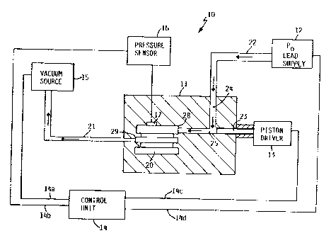
Referring to Figure 1, reference numeral 10 generally identifies a system for
pressure
3 5 casting of a battery terminal or battery part to inhibit formation of
cracks and tears in the
pressure cast battery terminal or battery part. The system 10 incudes a source
of
4
CA 02285742 1999-10-08
fn
pressurized molten lead 12 (which could be a source of pressurized alloy of
lead) for
directing molten lead under pressure into a mold 11. Mold 11 has a battery
terminal cavity
20 located therein with a runner 24 extending therefrom for supplying molten
pressurized
lead from pressurized lead source 12 to battery terminal cavity 20.
System 10 includes a vacuum source 15 which is connected to a cold spot i.e. a
spot that
cools at a rapid rate and cools before the rest of the molten metal in the
battery terminal
cavity 20. This enables the vacuum source 15 to evacuate the air from battery
terminal
cavity 20 through passage 21 prior to supplying molten lead to the battery
terminal cavity
20.
System 10 also includes a pressure sensor 16 having a probe 17 mounted in mold
11 with
probe 17 mounted in position to form a portion of the mold surface surrounding
the battery
terminal cavity 20. Pressure sensor probe 17 is preferably placed in a hot
spot of the mold,
i.e. a spot that cools at a slower rate. By placing the probe 17 in a portion
of the mold that
remains in a liquid state, one can monitor the pressure of the molten lead in
the liquid state
as the molten lead is supplied to battery terminal cavity 20.
Located in slideable relationship in passage 25 is a cylindrical piston 23 for
driving into
runner passage 25 of mold 11. A piston driver 13, which carries piston 23
connects to
mold 11 to hold piston 23 in an out of the way condition as molten lead is
being forced into
battery terminal cavity 20. Piston 23 provides a mechanical means for reducing
the volume
available for solidification of the lead therein.
In order to control the operation of system 10, a control unit 14 is included
with system 10.
Control unit 14 connects to vacuum source 15 via electrical lead 14a and to
pressure sensor
16 via electrical lead 14b. Similarly, control unit 14 connects to molten lead
supply 12
through electrical lead 14d and to piston driver 13 through electrical lead
14c.
3 0 The control unit 14, which can be a computer with appropriate software,
receives signals
from pressure sensor 16, which transmits the pressure of the molten lead in
battery terminal
cavity 20. That is, as the molten lead from the pressurized lead source 12
fills the battery
terminal cavity 20, the pressure on probe 17 is continually transmitted to
pressure sensor
16 and onward to control unit 14. When the pressure in battery terminal cavity
20 reaches
3 5 a predetermined level, control unit 14 sends a signal to piston driver 13
through electrical
lead 14c which quickly drives piston 23 into passage 25 to simultaneously
cutoff and seal
5
CA 02285742 1999-10-08
fn
passage 25 to prevent continued lead flow from runner 24. As piston 23 plunges
into the
passage, it reduces the volume for the lead that is in the liquid-to-solid
transformation
stage. By reducing the volume of the lead during the liquid-to-solid
transformation stage,
one can compensate for the lead shrinking and contracting as the molten lead
solidifies.
Consequently, the finished cast product is free of the tears and cracks that
would have a
detrimental effect on the performance of the battery terminal.
The system of Figure 1 is described with respect to volume shrinkage during
the liquid-to-
solid transformation stage; however, the system of Figure 1 can also be used
with the
method of volume shrinkage when the molten lead is in the molten state. If the
pressure of
the molten lead is to be increased the vacuum source connected to the mold is
sealed off
while the lead is in the molten state. This leaves a closed mold with liquid
molten metal
having substantially the same pressure throughout the mold. Next, with the
pressure of the
molten lead being maintained by the source of pressurized lead 22 a piston 23
is driven
inward to simultaneously shut off the supply of further molten lead while at
the same time
substantially increasing the liquid pressure throughout the mold. By
increasing the
pressure of the molten lead sufficiently the molten lead can solidify into a
part free of cracks
and tears. This process may not be used with all types of molds as it may not
be feasible to
build a mold to withstand the required high pressures throughout the mold. The
required
pressure of the molten lead to achieve a battery part free of cracks and tears
will to a certain
extend depend on the shape of the battery part and can be readily determined
through trial
and error.
Referring to Figure 2, mold 11 has been opened to reveal a portion of mold 11
and piston
2 5 23 which are shown in perspective view in relation to a portion of battery
terminal cavity
20. Extending out of one side of mold 11 is piston 23 having a head 31 for
engagement
with a hydraulic cylinder or the like. Battery terminal cavity 20 is defined
by a set of radial
fins 34 that project into the battery terminal cavity 20.
3 0 With system 10 one can pressure cast a lead battery terminal to inhibit
formation of tears
and cracks in the battery terminal. In order to inhibit the formation of tears
and cracks in
the cast battery terminal, the state of molten lead is continuously monitored
so that when the
molten lead enters the liquid-to-solid transformation stage, the volume of the
mold available
for the lead to solidify therein can be quickly reduced to force the lead,
while it is still
3 5 flowable, into the smaller volume. By rapidly reducing the volume and
maintaining
pressure on the molten lead during the critical liquid-to-solid transformation
stage, one
6
CA 02285742 1999-10-08
fn
causes the molten lead to solidify as a solid terminal or battery part
substantially free of
tears and cracks. It should be pointed out that in the liquid-to-solid
transformation stage,
the lead is in a condition where it can flow and is sometimes referred to as a
"mush".
Normally, as the molten lead goes through the liquid-to-solid transformation
stage, the
volume of lead contracts which results in a finished product that will have
cracks or tears
when it is completely solidified. The step of volume contraction at the moment
when the
lead is in the liquid-to-solid transformation stage produces a battery part
when cooled that is
substantially free of cracks and tears. This procedure is particularly useful
where the battery
cavity may have an unusual shape as the pressure produced by volume
contraction can be
transmitted throughout the part to produce sufficient pressure to prevent the
formation of
cracks and tears in the battery part.
Referring to Figure 1 to illustrate the operation of system 10, the mold 11 is
assembled
with the battery terminal cavity 20 located within the mold. One end of a
vacuum conduit
21 is attached to vacuum source 15, and the other end of vacuum conduit 21 is
attached to a
location on the mold 11 which is referred to as a "cold spot". That is, the
lead in this
portion of the mold is referred to as a "cold spot" as the molten lead in this
region will
solidify sooner than the molten lead being fed into the mold through runner
passage 25.
Consequently, as the lead begins to solidify in the "cold spot" the solidified
lead
immediately closes the end of conduit 21 which prevents molten lead from being
drawn
into the vacuum source 15. The location of a cold spot or cold spots will vary
depending
on the shape and size of the casting. For any particular shape battery
casting, one can
generally determine the cold spots by determining the regions of the mold that
are less
massive than others. If needed, one can also determine the cold spot through
trial and
error.
In addition to the position of a vacuum passage in mold 11, one places a
pressure probe 17
on the surface boundary of the battery mold cavity 20 in order to determine
when the
molten lead is in the liquid-to-solid transformation stage. While the
temperature could be
3 0 measured to determine when the lead reaches the liquid-to-solid
transformation stage, the
time lag between the actual temperature of the lead and the measured
temperature may be
sufficiently long so that the actual temperature of the molten lead may have
cooled
sufficiently so the lead is no longer in the liquid-to-solid transformation
stage even though
the temperature probe indicates that the temperature of the lead is in the
liquid-to-solid
3 5 transformation stage. However, by measuring the pressure using a pressure
probe, one is
able to obtain a pressure reading which can more quickly determine when the
molten lead
7
CA 02285742 1999-10-08
fn
enters the liquid-to-solid transformation stage. By being able to more quickly
determine the
molten state of the lead, one still has sufficient time to active the piston
driver 13 to drive
the piston 23 into the molten lead and force the molten lead to flow into a
reduced volume
before the molten lead passes completely through the liquid-to-solid
transformation stage.
With the system 10 in the condition shown in Figure 1, the control unit 14 can
activate the
molten lead supply to deliver molten lead under pressures of 40,000 psi or
higher to deliver
molten lead to pipe 22 which delivers the molten lead under pressure to runner
24. The
molten lead flows in the directions indicated by the arrows in runners 24 and
25. Note, in
this condition piston 23 is located behind runner 24 so that molten lead flows
from runner
24 to runner 25 and into battery terminal cavity 20. While the molten lead is
flowing into
battery terminal cavity 20, the vacuum source is removing air from battery
terminal cavity
with the air flowing through vacuum source 15 as indicated by arrow in conduit
21. As
previously mentioned, air evacuation conduit 21 terminates at a cold spot
indicated by
15 reference numera129 while the molten lead enter battery terminal cavity at
what is
considered a hot spot 28 , i.e. an area where the lead solidifies last.
Once the molten lead enters the battery terminal cavity 20, the molten lead
fills up the
battery terminal cavity and the lead in the cold spot 29 begins to solidify
thereby preventing
20 further molten lead from being drawn out of the mold and into conduit 21.
It should be
pointed out that the size of the opening in the cold spot is kept sufficiently
small so that the
molten lead will solidify and quickly fill the open end of conduit 21, yet the
conduit 21 is
sufficiently large so that the air can quickly be evacuated from the battery
terminal cavity
20.
As the vacuum passage 21 is sealed off, the pressure in the battery terminal
cavity 20
begins to rise under the pressure of the molten lead supply. When the pressure
reaches a
predetermined level, which can be determined by the shape and size of the
battery terminal
being cast, the control unit 14 senses the pressure and sends a signal to
piston driver 13.
3 0 Piston driver 13 includes a quick action hydraulic cylinder or the like
which quickly fires
piston 23 foreword, which simultaneously cuts off the supply of additional
molten lead
from runner 24, while reducing the volume in which the lead will solidify.
If desired, the decrease in volume can be determined based on trial and error.
That is, by
3 5 observing the finished product for cracks and tears, one can determine if
more volume
8
CA 02285742 1999-10-08
fh
reduction is necessary as insufficient volume reduction of the lead or lead
alloy leaves
cracks and tears in the finished battery terminal.
Figure 3 shows a portion of system 10 with mold 11. In the condition shown in
Figure 3
the piston 23 has been driven into the passage 25 thereby cutting off the flow
of additional
molten lead through runner 24. At the same time the end of piston 23 has
forced the molten
lead in passage 25 into the mold by pushing the molten lead ahead of end 23a
of piston 23.
Thus the volume for molten lead to solidify therein has been decreased by
forcing the
piston end 23a proximate the battery terminal cavity 20. In the preferred
method, the piston
end 23a is driven to the outer confines of the battery terminal cavity 20
thereby eliminating
a protrusion on the battery casting. That is, the end 23a, when in the piston
shown in
Figure 3 defines the end of a portion of the battery terminal being cast
therein.
Figure 4 shows an alternate embodiment of my system that uses a piston 41 that
is
maintained under a predetermined pressure. The components of system 50 that
are identical
to the components in system 10 are shown with identical numbers. System 50
includes a
housing 40 which is secured to mold 11. Housing 40 includes a cylinder 42 that
has a
slidable piston 41 located therein. A chamber 43 is located above the top end
of piston 41.
A high pressure source 45 connects to chamber 43 though conduit 46. The
control for high
pressure 45 source comes from control unit 14 and through lead 14e. Piston 41
is shown in
the slightly elevated condition and during the course of its operation the
lower end 41 a of
piston 41 will move from a position flush with the surface of the battery
terminal casting 20
to a position above the battery terminal casting 20 (shown in Figure 4) and
eventually again
to a position where end 41a is flush with the surface of the lead battery
terminal casting 20.
In the embodiment shown in Figure 4, the piston 41 is positioned in a hot spot
in the mold.
The lead is then injected under pressure into mold 28 though runner 24. During
this stage
of the molding process the injection pressure of the lead builds to a level
where the pressure
of the lead in the mold is sufficient to force piston 41 upward as shown in
Figure 4. As the
mold begins to cool and the supply of lead to the battery terminal cavity is
terminated, the
pressure in the battery terminal cavity 20 begins to decrease. As the pressure
in the mold
decreases, it reaches a point where the pressure forces on the top end of
piston 41 become
greater than the pressure forces on the bottom end 41a of piston 41. In this
condition piston
41 is driven downward by the pressurized air in chamber 43 causing the volume
available
3 5 for the lead to solidify in to be reduced. As long as the piston 41 is
located in a hot spot on
the mold, the lead is forced into a smaller volume as it solidifies.
Consequently, the
9
CA 02285742 1999-10-08
~
reduction of volume causes the battery casting formed therefrom to be formed
substantially
free of cracks. If desired, one can ensure that the lead does not solidify in
the area where
the piston contacts the molten the piston by maintaining a temperature of the
piston in
excess of the molten lead in the mold.
Figure 5 is a cross-sectional view showing a portion of a mold 50 in cross
section. A
battery terminal cavity 51 is shown therein having an upper cylindrical
electrical contact
surface 51a and a lower non-electrical contact surface 51b. The electrical
contact surface is
defined as the surface of the battery terminal that is mechanically clamped to
a battery cable
to transmit electrical energy from the battery terminal to the battery cable.
The non-electrical
contact surface 51b is the surface of the battery terminal that is either
connected to the
battery casing, remains free of contact with another part or is fused to
another battery part.
Generally, the electrical contact surface should have a smooth and continuous
fmish for
mechanically engaging a battery clamp thereto while smoothness and continuous
of the
non-electrical contact surface is less critical because there are no
mechanical connections
thereto. Mold 50 includes a blow hole or vent passage 56 for removing air from
the battery
mold cavity. Depending upon the conditions of molding, a vacuum source could
be
connected thereto to remove air more rapidly. A cylindrical piston 54 is
positioned in a
cylindrical passage with the piston 54 having an end source 51b flush with the
surface of
the non-electrical contact surface of the mold cavity during the pressure
casting process. A
piston driver 53 is positioned proximate the mold 50 and includes therein
means (not
shown) for driving the piston 54 toward the battery terminal cavity 51 or for
retracting the
piston 54 away from the battery terminal cavity.
2 5 Figure 6 is a cross-sectional view of the mold in Figure 5 showing a
solidified battery
terminal 60 located in battery cavity 51. The piston 54 has been driven into
the solidified
battery terminal 60 with sufficient force so as to at least pa.rtially cold
form the solidified
lead into a battery terminal which is free of cracks and tears. That is, the
end of piston 54a
is shown penetrating into the batter terminal to decrease the volume of the
battery terminal
3 0 cavity while at the same time mechanically deforming at a least a portion
of the battery
terminal 601oca.ted therein. In the embodiment shown, the mechanical pressure
is sufficient
to force solidified lead through passage 56 and out of mold 50 as indicated by
solidified
lead 60a extending from vent passage 56. Thus, one can pressure cast a battery
part and
allow the pressure cast battery part to solidify and while the battery part is
still in the mold
3 5 but in the solidified state a piston can be driven into the solidified
part to mechanically
deform the lead which will remove cracks or tears in the battery terminal that
occur as a
CA 02285742 1999-10-08
fn
result of the pressure casting process. Figure 6 shows that the piston can be
driven into the
battery terminal 60 to leave a recess within the battery terminal. As the
piston is driven into
the portion of the battery terminal that contains the non-electrical contact
surface, a feature
such as a recess can be tolerated thereon without adverse conditions for
operation of the
battery terminal. This procedure of volume contraction is suitable when the
battery part has
a shape so that the volume contraction can cause the deformation of the lead
in remote
portions of the battery part. That is, in some battery parts the configuration
of the battery
part may be such that a volume reduction in one region produces only partial
cold
deformation or reworking the battery part thereby leaving a battery part with
a crack or tear.
However, in those battery parts where the cold deformation can effectively
move metal
throughout the battery cavity the volume contraction can be performed after
the
solidification of the battery part. The advantage of this method is that the
internal pressure
within the mold is increased locally but not throughout the mold as the
solidified battery
part does not transmit pressure forces in the same manner as if it were a
liquid.
Figure 7 is a cross-sectional view showing a portion of a mold 50 and a piston
54 that is
positioned having its end surface 54a spaced from the non-electrical contact
surface 51b. A
pressure cast solidified battery terminal 65 is shown therein with a
solidified extension 65a
extending outward from the battery terminal 65 to the end surface 54a of
piston 54. In this
condition, the extension 65a has solidified as an integral part of the battery
terminal. Battery
terminal 65 having been formed by a pressure cast process can include cracks
and tears. In
order to remove any tears or cracks the piston 54 is driven toward battery
terminal post 65
with sufficient force to force the material in extension 65a into the battery
terminal and
thereby mechanically deform the battery terminal to a condition wherein the
tears and cracks
are removed.
Figure 8 illustrates the driving of the piston to a condition flush with the
surface of the
battery terminal. By driving the piston end 54a to a condition flush with the
battery
terminal 65, the battery terminal is provided with a continuous surface.
Consequently, the
3 0 method illustrated by Figure 8 can be used on either the non-electrical
contact surface or the
electrical contact surface as the finished surface remains flush with the
adjacent surface.
Figure 9 is a cross-sectional view showing a portion of a mold 55 with a
solidified battery
terminal 66 therein. A piston 54 is positioned having its end surface 54a
spaced from the
3 5 mold cavity end surface 51b. In the condition shown, a solidified
cylindrical extension of
length Ll extends from battery terminal 66.
11
CA 02285742 1999-10-08
fn
Figure 10 is a cross-sectional view of the mold in Figure 9 showing the end of
the piston
driven to a condition which is also spaced from the end surface of the mold
cavity. That is
the piston has been driven in passage 55 until the extension 66b has been
shortened to
length L2. The purpose of mechanically reducing the volume of the solidified
battery
terminal 66 is to cold form at least a portion of the metal in the battery
terminal to thereby
relieve any cracks or tears in the pressure cast battery terminal. The method
illustrated in
Figures 9 and 10 requires less precession in the piston movement to deform the
metal into a
shape free of cracks and tears. For example, the amount of force applied to
piston 53 could
be the determining factor of the travel of the piston rather than the length
of piston travel
determining the pressure of deformation on the battery terminal.
Figure 11 is a view of a battery terminal of Figure 10 with the pressure cast
extension 66b
being schematically shown as being sheared off. In practice the removal of the
battery
terminal 66 from the mold may cause the extension 66b to shear off and remain
in
cylindrical passage 55. That is, the extension 66b is sufficiently small in
diameter so that
the extension can be broken with the battery terminal removal force.
To illustrate the removal of the extension 66b from the mold, reference should
be made to
Figure 12 which is a partial cross-sectional view of the piston of Figure 10.
Piston 53 is
shown driving the pressure cast extension 66b from the passage 55. Thus with
the method
illustrated in Figures 9-12 one can leave an extension on the cast battery
terminal and then
break the extension off during the removal of the battery terminal. The use of
the piston 54
allows one to clear the passage 55 for the next casting.
Figure 13 is a front view of a two-metal battery connector 70 having an
intermediate
member 73 with a first connector end 71 having an opening 71a and a second
connector
end 72 having an opening 72a therein. The exterior of connector 70 is lead.
3 0 Figure 14 is a cross-sectional view taken along lines 14-14 of Figure 13
showing the
extension connector 73 of lead and the inner core 75 which is a different
metal such as
copper. Core 75 is surrounded by a lead sheathing that has been pressure cast
thereon.
To illustra.te the pressure casting of the battery part of Figure 13,
reference should be made
3 5 to Figure 15 which is a cross-sectional view of a mold 80 and a holding
apparatus for
pressure casting the battery connector of Figure 13. Holding apparatus
comprises a pair of
12
CA 02285742 1999-10-08
fh
retractable members 82 and 83 that are oppositely disposed with the core 75
being
supported therebetween in a condition that leaves an envelope of space 86
around core 75
to allow for molten metal to flow therein. Retractable members 82 and 83 are
held in
pressure contact with core 75 through means not shown. A source of pressured
lead 81 is
located in fluid communication with mold cavity 86 through feed runner 82. In
the
condition shown, the mold 80 is ready to receive molten lead. In the condition
to receive
molten lead a first piston 84 is located in a retracted condition to provide a
mold space 84a
in front of the end of piston 84 and similarly, piston 85 is located in a
retracted condition to
provide mold space 85a in front of the end of piston 85. During the pressure
casting of
connector 70, the molten lead will be forced into void 86 and into the space
85a and 85b.
Once the lead in the mold has solidified to support core therein, the
retractable members 82
and 83 are retracted leaving the pressure cast lead to support the core
therein. The
withdrawn of the retractable members 82 and 83 will leave a void in the
solidified material
in mold 80. In order to fill the voids produced by retraction of retractable
members 82 and
83, the pistons 84 and 85 are driven inward to a condition flush with the
exterior of the
remaining portion of the mold.
Figure 16 is cross-sectional view of a mold and holding apparatus of Figure 15
with a pair
of retractable members 82 and 83 in the retracted position and the driving
pistons 84 and 85
in the extended position. In this condition, the metal present in region 85a
and 84a of figure
14 has been forced into the voids produced by the withdrawal of retractable
members 82
and 83. Consequently, the connector 70 can be formed in a pressure cast
process with the
completion of the battery connector accomplished with a deformation of the
pressure cast
lead to thereby produce a finished product.
Figure 17 is a cross-sectional view of an alternate embodiment of a pressure
cast part 91
that has formed a cylindrical extension 91a thereon. The length of the
cylindrical extension
91a is limited by the end of an annular drive punch 95.
Figure 18 shows the battery part of Figure 17 with the annular drive punch 95
driven into
the solidified extension 91a to cold form the battery part 91 free of cracks
and voids. Thus
with the present process, one can pressure cast a variety of battery parts and
through a
process of decreasing the volume during either the pre-solidification state or
the solidified
state, one can produce a battery terminal that is free of tears and cracks.
13
CA 02285742 1999-10-08
fh
Figure 19 shows a mold 100 with a core pin 101 and slidable collar 108 for
pressure
casting a battery part which is defined by cavity 110 which includes the
annular cavity
surrounding core pin 101. In operation of the mold of Figure 19, molten lead
under
pressure enters runners 103 to fill the battery part cavity 110. A slidable
collar 108 is
located within fixed collar 109 with the end of collar 108 and the inner
portion of collar 109
defining a portion of the battery part. Casting of the battery part with the
collars in the
position shown produces an annular extension of the battery part in the
battery cavity
portion defined by 110a. In order to provide the volume contraction of the
battery part to
provide a battery part free of cracks and tears, there is included a piston
106 that is slidable
in chamber 107. A first port 104 receives a first fluid and a second port 105
receives a
second fluid. When the pressure in port 105 is increased rapidly, it forces
piston 106
upward which drives collar 108 upward into the battery cavity region 110a
which
compresses the annular lead extension located therein by reducing the volume
available for
the lead extension. In the mold shown in Figure 19, the collar 108 can be
driven upward to
reduce the volume while the lead is in the transition state between liquid and
solid or when
the lead has cooled. If the lead has cooled to solid state before the
slideable collar 108 is
driven upward the lead is cold formed into a battery part. The piston 106 can
be lowered
again by increasing the pressure in port 104 and reducing the pressure in port
105, thus
withdrawing the piston 106 from the drive collar 108.
Figure 20 shows a partial schematic of my closed system 210 for pressure
casting lead
articles while maintaining the molten lead in the runners in a molten state.
Closed system
210 for molding lead articles under pressure incudes a source of
pressurizeable molten lead
212, a control module 211, a runner 214 for directing molten lead to a housing
215 which
includes a shut-off valve that controls the flow of molten lead into a mold
219. Control
module 211, which may be a computer with appropriate software, connects to the
source of
molten lead 212 through a lead 213. Similarly, control module 211 connects to
a power
cylinder 218 through a lead 217. A third lead 216 connects control module 211
to a power
cylinder located in housing 215.
In the embodiment shown in Figure 21, mold 219a includes a bleed chamber 231
for
allowing air to escape from the mold cavity therein. Bleed chambers are known
in the art
and generally comprise a small necked passage that allows air to escape from
the mold
cavity as the molten lead is injected into the mold cavity. The passage has a
small neck to
3 5 allow air to escape but when lead enters the small necked bleed passage it
quickly cools and
solidifies thereby closing off the passage and preventing the escape of molten
lead.
14
CA 02285742 1999-10-08
fn
Mold 219 is shown mounted on a pair of rails 221 to permit one to slide mold
219 with
connector 222 into temporary engagement with a connector 223 on housing 215
through a
power cylinder 218. The embodiment as described in Figure 21 with housing 215
in
section is shown in further detail in Figures 24-28. In a further embodiment
illustrated in
Figures 1-23 the mold connector 222 remains in contact with connector 223
during the
molding process.
With the closed system operation of the present invention, the molten lead is
maintained in
a molten state by having the housing 215 , which is usually iron, at a
temperature above the
melting point of lead. This ensures that the molten lead therein will remain
in a molten
state. However, in order to cast a product, the mold 219 must be maintainable
at
sufficiently low temperature so that molten lead injected into mold 219 can
solidify therein.
In order to ensure that the mold is at sufficiently low temperature, either of
two systems can
be used to minimize heat transfer between the mold 219 and the housing 215.
One system
may be suitable for molds that can rapidly dissipate excess heat and the other
system may
be more suitable for molds that cannot dissipate heat as rapidly.
In the embodiment shown in Figures 21 and Figures 24-28 the mold is
temporarily
maintained in contact with the housing 215 by sliding mold 219 away from
housing 215
during a portion of the molding cycle thereby limiting the amount of
conductive heat
transfer from the housing 215 to mold 219 by limiting the time of contact
between housing
215 and mold 219. In the embodiment shown in Figures 2-4 thermal insulation is
used to
thermally isolate the mold from the housing 215 to thereby limit the amount of
heat transfer
from housing 215 to mold 219.
The housing 215 and mold 219a of an alternate embodiment are shown in cross-
section in
Figures 2-4. Mold 219a includes a mold cavity 230 with a bleed passage 231
connected
thereto. Bleed passages are known in the art and are generally narrow passages
that
connect to the mold cavity to allow air to escape from the mold as the molten
lead is injected
into the mold. As the passage is narrow, the entrance of molten lead therein
is quickly
cooled thereby causing the passage to be blocked by the molten lead. If it is
desired to have
the cast part free of small air pockets, one can use an air bleed passage, on
the other hand if
small air pockets are acceptable in the cast part the bleed passage need not
be used at all.
3 5 Mold 219a is shown with connector 233 in engagement with connector 234 and
the mold
219a thermally isolated from housing 215 by insulation pads 232.
CA 02285742 1999-10-08
rn
Housing 215 includes a power cylinder 235 that includes a slidable piston 236
that can be
powered in either direction by a signal from control module 211. Connected to
slidable
piston 236 is a cylindrical retractable and extendible member 237 that coacts
with runner
214 to form a shut off valve 239 to control the injection of molten lead into
mold cavity
230. Runner 214 is shown in Figure 22 to include a cylindrical chamber 214c, a
smaller
cylindrical passage 214b located at a right angle to chamber 214c and a
further cylindrical
passage 214a located in mold 219a which connects to mold cavity 230. Housing
215
including shut off valve 239 are maintained at sufficiently high temperature
through an
external heat source (not shown) so that molten lead located therein will
remain in the
molten state.
Shut-off valve 239 has a closed position, which is illustrated in Figure 21,
to prevent
molten lead from flowing out of runner 214 and an open position, which is
illustrated in
Figure 22, for allowing molten lead to flow into mold cavity 230a. In the
closed position
as shown in Figure 21, the slidable piston or cylindrical member 237 seals off
runner
passage 214b to prevent further molten lead from entering mold cavity 230a.
The seal is
obtained by a close tolerance fit between the outside diameter of member 237
and the inside
diameter of runner passageway 214b. In the open position, which is shown in
Figure 22,
the molten lead is allowed to flow through runner passage 214c, 214b, and 214a
and into
cavity 30a as indicated by the arrows. In this condition, the molten lead is
injected under
pressure into cavity 30a which is generated by a slidable piston in an
immersion housing
261. In order to provide smooth operation, the mold and the housing include
mating
members for providing a continuous inline passage between the mold cavity and
the
housing, and an alignment guide such as a beveled annular edge on either the
end of
cylindrical member 237 or the passageway 214b to ensure that any misalignment
of the
cylindrical member with the passageway is self correctable.
Figures 24-28 show the embodiment wherein the mold 219 is slid into temporary
engagement with the housing 215. Referring to Figure 24, mold 219 is shown
setting on
rails 221 with mold 219 connected to an extension and retractable member 218a
which is
driven by the two way power cylinder 218 shown in Figure 21. The mold 219 is
shown
without an air bleed passage. Figure 24 shows the mold in a position to
minimize heat
transfer between housing 215 and mold 219. In this condition, connector 233
and
3 5 connector 234 are in disengagement and mold 219 is spaced from housing 215
to thereby
limit conduction heat transfer from housing 215 to mold 219. In this condition
the cylinder
16
CA 02285742 1999-10-08
fn
member 237 is shown sealing the runner 214 to prevent molten lead from
entering mold
cavity 230.
Figure 25 shows that mold 219 has been brought into engagement with housing
215
through extension of member 218a, which causes mold 219 to slide along rails
21. In this
condition the mold cavity 230 is ready to receive molten lead through the
runner 214a,
however, the cylindrical member 237 is maintaining molten lead within the
runner 214 by
the close tolerance fit between cylindrical member 237 and cylindrical runner
passage 214b.
The step of closing the runner includes positioning piston 237 sufficiently
far so as not to
be in engagement with the mold but sufficiently far so as to maintain the
piston in a
blocking condition in the runner to thereby prevent molten lead from escaping
from the
runner.
Figure 26 shows shut-off valve 239 in the open position with the molten lead
flowing into
mold cavity 230. Note, the end 237e of cylindrical member 237 is positioned in
a retracted
condition so as not to block flow of molten lead into passage 214b.
Figure 27 shows the shut-off valve 239 in the closed condition with end 237e
extending
into runner passage 214b to seal off the passage 214b and prevent further
molten lead from
flowing into cavity 230. The molten lead 251 is in a state of solidifying in
cavity 230 and
the lead 251 includes a neck 251a that extends into runner passage 214a. A
feature of the
present invention is that one can introduce the intensification process to the
forming of the
lead part in cavity 230.
In the intensification process, the state of molten lead is monitored so that
when the molten
lead enters a transformation stage from liquid-to-solid, the volume of the
mold available for
the lead to solidify therein is quickly reduced to thereby cause the molten
lead to flow into
the remaining volume while one maintains increased pressures on the molten
lead. As the
molten lead solidifies under the reduced volume and increased pressure, it
produces a lead
3 0 part that is substantially free of both tears and cracks. In still another
variation of the
process, the lead part is allowed to solidify in the mold, but before removal
of the lead part
from the mold a piston is driven into the lead part with sufficient force so
as to at least
partially cold form a portion of the lead part to thereby produce a lead part
that is free of
cracks and tears. Thus, it is apparent that with the present process of a
closed system the
3 5 cylindrical member 237e is configured to not only shut off the flow of
molten lead but also
can be driven into the solidifying lead in mold cavity 230 to increase or
intensify the
17
CA 02285742 1999-10-08
fn
pressure to produce a lead part that is substantially free of both tears and
cracks. Thus the
shut-off valve can both control the flow of molten lead to the mold cavity and
intensify the
pressure of the lead in the mold.
While the transfer of molten lead from the runner 214 to the mold 219 had been
described,
the closed system also includes a source of pressurized lead 212. The source
of
pressurized lead is shown in Figures 29-13.
Figure 29 shows a source of pressurizeable molten lead 212 including a vat 260
of molten
lead 29 having an immersion housing 261 therein with a slidable piston 262 for
increasing
the pressure of the molten lead in the immersion housing 261 and runner 214.
The
immersion housing 261 has an inlet 263 which is maintainable in the lower
portion of the
vat 260 of molten lead to prevent air from being drawn into the immersion
housing when a
fresh charge of molten lead is brought into the housing. That is the inlet 263
is located
below the top 229a of the vat of molten lead. Immersion housing 261 is known
in the art
and is used to force lead from a vat of molten lead. In the present system,
the immersion
housing is coupled to the mold cavity through a closed system that enables a
charge of lead
to be removed from the system or added to the closed system without disrupting
the
condition of the molten lead in the system.
Figure 29 shows the piston 262 at the beginning of the cycle with molten lead
2291oca.ted
in chamber 265. As lead is substantially incompressible, the forcing of piston
262
downward forces molten lead trough runner passage 214e and runner 214. Runner
214
comprises a passage in a housing that is maintained at a temperature to
maintain the lead in
2 5 a molten state and provides an airtight passageway between immersion
housing 261 and
mold 219.
Figure 30 shows piston 262 in the compressed position where the lead 29 in the
runners
214 has been forced into the cavity of mold 219. After compressing the lead to
the position
3 0 shown in Figure 30 the shut-off valve 235 is closed by extending
cylindrical member 239
into the passage 214b. Consequently no air can get into the runners. By
maintaining the
appropriate pressure on the lead in the immersion housing, one can maintain
the pressure of
the lead in the runners at a fixed level.
3 5 Figure 31 illustrates what happens in the next step as the piston 262 is
raised by a signal
from the control module. As the piston is lifted upward, a vacuum is formed in
the system.
18
CA 02285742 1999-10-08
fn
That is the runners now have a negative pressure as the piston 262 is brought
upward to
expand the volume of the system without introducing air or molten lead into
the system.
Figure 32 shows the piston drawn up slightly further to expose the inlets 265a
which
allows molten lead 29 to be drawn into chamber 265 through the vacuum within
the
system. In this condition the system has received a fresh charge of molten
lead and is
ready to force a charge of molten lead into the mold cavity.
Thus with the present system I have provided a method of pressure casting a
lead article
comprising the steps of 1) increasing the pressure of a source of molten lead
sufficiently to
force the molten lead to flow in a liquid state into a mold cavity 2)
maintaining the mold
cavity at a sufficiently low temperature so that when molten lead is injected
therein the
molten lead solidifies and 3) closing a runner to mold cavity 219 while
maintaining molten
lead 229 in a closed system to prevent entrapment of air in the molten lead so
that a fresh
charge of molten lead can be introduced into the closed system by retracting
piston 262.
The closed system shown for molding lead articles without the introduction of
air includes
a control module 211 which can automaticaily control the sequence of system
operations.
The system further includes a source of pressurizeable molten lead 212 and a
runner 214
that connects to a mold 219 having a mold cavity 230. The mold is maintainable
at
sufficiently low temperature so that a charge of molten lead located in mold
cavity can
quickly solidify to thereby form a solidified casting. In order to provide for
continuous
production of cast parts the housing 215 includes a runner 214 for flow of
molten lead
therethrough and for maintaining the lead in a molten state either through
heating of the
runner with an external heater or by maintaining insulation about the runner
or housing. In
either case, the runner is maintainable at sufficiently high temperature to
continuously
maintain molten lead therein in a molten state so that the mold cavity can be
refilled with a
fresh charge of molten lead from the runner when a solidified casting is
removed. In order
to start or stop the flow of molten lead to the mold, shut-off valve 239 has
an open position
3 0 that allows molten lead to flow into the mold cavity 230 and a closed
position that prevents
molten lead from flowing out of the runner 214. During the molding process as
the lead in
the mold cavity solidifies, one can intensify the pressure by driving cylinder
member 237
of the shut-off valve 239 along the runner and toward the mold cavity to
further increase
the pressure in what is referred to as an intensification position. Once the
molded part is
3 5 released from the mold, the process is repeated.
19
CA 02285742 1999-10-08
tn
It will be appreciated that with the present system not only can lead be
maintained in a
molten state, but that the entire system for handling the molten lead need not
be built to
withstand the pressure of intensification as only the mold experiences the
high
intensification pressures.
While the system has been described with respect to use with lead it is
envisioned that the
system can be used with other metals.