Sélection de la langue

Search

Sommaire du brevet 2285887 

Énoncé de désistement de responsabilité concernant l'information provenant de tiers

Une partie des informations de ce site Web a été fournie par des sources externes. Le gouvernement du Canada n'assume aucune responsabilité concernant la précision, l'actualité ou la fiabilité des informations fournies par les sources externes. Les utilisateurs qui désirent employer cette information devraient consulter directement la source des informations. Le contenu fourni par les sources externes n'est pas assujetti aux exigences sur les langues officielles, la protection des renseignements personnels et l'accessibilité.

Disponibilité de l'Abrégé et des Revendications

L'apparition de différences dans le texte et l'image des Revendications et de l'Abrégé dépend du moment auquel le document est publié. Les textes des Revendications et de l'Abrégé sont affichés :

  • lorsque la demande peut être examinée par le public;
  • lorsque le brevet est émis (délivrance).
(12) Demande de brevet: (11) CA 2285887
(54) Titre français: SUPPORT DE SUSPENSION VERROUILLABLE
(54) Titre anglais: LOCKABLE SUSPENSION HANGER
Statut: Réputée abandonnée et au-delà du délai pour le rétablissement - en attente de la réponse à l’avis de communication rejetée
Données bibliographiques
(51) Classification internationale des brevets (CIB):
  • E05B 65/00 (2006.01)
  • B62D 43/00 (2006.01)
  • B62H 03/12 (2006.01)
(72) Inventeurs :
  • SUNDHAGEN, GUNNAR (Norvège)
(73) Titulaires :
  • LENA SUNDHAGEN
(71) Demandeurs :
  • LENA SUNDHAGEN (Norvège)
(74) Agent: ROBIC AGENCE PI S.E.C./ROBIC IP AGENCY LP
(74) Co-agent:
(45) Délivré:
(22) Date de dépôt: 1999-10-15
(41) Mise à la disponibilité du public: 2000-04-16
Licence disponible: S.O.
Cédé au domaine public: S.O.
(25) Langue des documents déposés: Anglais

Traité de coopération en matière de brevets (PCT): Non

(30) Données de priorité de la demande:
Numéro de la demande Pays / territoire Date
19984850 (Norvège) 1998-10-16

Abrégés

Abrégé anglais


Lockable suspension hanger (1) to firmly hold and firmly lock one or more
items to a
wall or any other mainly vertical surface. The suspension hanger comprises a
bracket
(2) that is designated to be attached to the wall, at least one outwards
oriented rod (3)
and a lock (4), which is designated to be attached to the rod (3) and locked
onto this.
The rod (3) is pivot mounted in the bracket (2), so that the rod (3) in unused
position
can be swung against the wall.

Revendications

Note : Les revendications sont présentées dans la langue officielle dans laquelle elles ont été soumises.


6
c l a i m s
1.
Lockable suspension hanger (1) to firmly hold and firmly lock one or more
items to a
wall or another mainly vertical surface, comprising a bracket (2) which is
designated to
be attached to the wall or similar, at least one outward oriented rod (3) and
a lock (4),
which is designated to be attached to the rod (3) and firmly locked to this to
prevent the
item from being removed from the rod (3), characterized in that the rod (3)
being pivotable supported in the bracket (2), so that the rod (3) in unused
position can
be swung against the wall.
2.
Lockable suspension hanger according to claim 1, characterized in that the
rod (3) comprises a first part (8), which is pivot mounted in the bracket, and
a second
part (9), which is outward oriented from the bracket (2), which first and
second part (8,
9) are firmly connected to each other in a mainly right angle.
3.
Lockable suspension hanger according to claim 2, characterized in that the
first part (8) is rotatable received in the bracket (2) in a channel (7) which
is formed by
oppositely modelled protuberances (7) in the bracket (2).
4.
Lockable suspension hanger according to one of the claims 1-3, characterized
in that the rod's (3) outward oriented part (9) comprising at least one groove
(10),
notch or similar in which a locking pawl or similar on the lock (4) can come
into
position.
5.
Lockable suspension hanger according to claim 4, characterized in that the
rod (3) comprises several subsequently placed grooves (10), notches or
similar, in
which the lock (4) selectively can be firmly locked in a chosen position from
the bracket
(2).

7
6.
Lockable suspension hanger according to claim 5, characterized in that the
lock's (4) locking pawl and the rod's (3) grooves (10) or similar are shaped
in such a
proportion to each other that a ramp is formed on the locking pawl and/or on
each
groove (10), so that the lock (4) can be pushed over the grooves (10) in
locked position
in direction towards the bracket (2), but that in the opposite direction is
formed an
engagement between the locking pawl and the grooves (10), so that the lock (4)
is
restrained from relocating in this direction when the lock (4) is locked.
7.
Lockable suspension hanger according to one of the claims 4-6, characterized
in that the lock (4) comprises a continuous hole (12), through which the rod's
(3)
outward oriented part (9) can come into engagement with the lock (4).
8.
Lockable suspension hanger according to one of the previous claims 1-7,
characterized in that the bracket (2) is designated to be attached by means of
screws to the wall or similar, said screws being designated to be covered by
the firmly
locked item when the suspension hanger (1) is in use.
9.
Application of the lockable suspension hanger (1), comprising a bracket (2)
which is
designated to be fastened to a wall or any other mainly vertical surface, with
at least one
from the bracket (2) outward oriented rod (3) and a lock (4), which is
designated to be
attached to the rod (3) and firmly locked to this, to prevent the item from
being removed
from the rod (3), where the rod (3) is pivot mounted in the bracket (2), so
that the rod
(3) in unused position can be swung against the wall, for firmly locking at
least one
vehicle wheel or mounting wheel, by the rod (3) being thread through an
opening in the
mounting wheel, like a wheel bolt hole or a hub hole, the wheel or mounting
wheel
being brought to close contact with the wall or similar and the lock (4) being
placed in
tight contact against the mounting wheel, so that the bracket (2) becomes
inaccessible
from the outside.

Description

Note : Les descriptions sont présentées dans la langue officielle dans laquelle elles ont été soumises.

CA 02285887 1999-10-15
1
Lockable suspension hanger
The present invention relates to a lockable suspension hanger in order to keep
in
s position and to lock one or more items to a wall or any other mainly
vertical surfaces,
comprising a bracket which is designated to be attached to a wall or similar,
at least one
outward oriented rod and a lock, which is designated to be attached to the rod
and
locked onto this.
io Several suspension hangers of the above mentioned type are known:
US-5.638.710 shows firm locking of a spare tyre in a special lifting appliance
which is
used on certain car models. The tyre is here placed horizontally and is
hanging in a wire
20, and the locking appliance is designated to have the function to prevent
the tyre to be
is removed from the lifting appliance.
US-4.328.687 shows an appliance for locking a firearm fixedly to a wall. The
appliance
involves two parts, one part comprising a cylindrical lock which is to be
attached to the
wall, and one part comprising a rod and a disc, which are to be lead through
the arm's
zo trigger guard. To prevent that the locking appliance can be unscrewed from
the wall, it
also comprises a disc 34, which covers the screws that attach the appliance to
the wall.
The appliance is not pivotable in relation to the wall. The rod part may be
removed, but
implies however, the disadvantage that it might be lost.
zs US-4.751.833 shows a locking appliance for firm locking of a spare tyre to
a fastening
bracket on a vehicle. The locking appliance comprises several parts, among
others nuts
34, which has to be screwed on and unscrewed when the spare tyre is to be
fixed or
removed. The appliance is firmly locked by the help of an ordinary padlock.
This device
can not pivot in relation to the side of the vehicle.
US-1.790.656 shows an additional appliance to fasten a spare tyre to a
vehicle. The
locking appliance replaces one of the nuts that fixes the spare tyre to the
fastening
bracket, and is operated by a cylinder lock. Nor this appliance can be
pivoted.

CA 02285887 1999-10-15
2
SE-436376 shows an additional locking appliance for firm locking of several
spare tyres
either to the floor or to the wall. The appliance comprises a padlock that can
be run
through one or more holes in a rod. Neither this appliance can be pivoted to
the wall.
US 4679717 shows a carrier for spare wheels, for mounting to an automobile. It
comprises a bracket and an arm linked to the bracket. Distal on the arm a
spare wheel
can be attached by bolts and nuts. The arm can be swung outwardly from the
car.
io Us 5806736 describes a similar device, in which the arm can be locked
against the car
by a pad lock.
US 4794771 describes a device similar to US 5638710. The main difference being
that
the arm is connected to a tube on the underside of the car and can be pivoted
relative to
is this tube around an axis transverse to the tube.
US 3940178 show a device to attach a spare wheel to the inside wall of a pick
up. It
comprises a pivotable arm, which can be swung upwardly. If released it will
fall down
into a protruding position again. The wheel can be locked by a chain extending
from the
zo arm to a place at the opposite side of a wheel well.
US 4153188 show a device to attach a spare wheel to an automobile. It
comprises an
arm, which at one end can be detachable inserted into a bracket on the
vehicle. At its
opposite end the arm has a series of holes or notches which a lever arm can be
brought
zs to engagement with. The lever is used to press the spare wheel against the
surface on
which the bracket is mounted.
An essential disadvantage with several of the known hanging appliances for
wall
installations is that a rod will protrude from the wall also when the hanging
appliance is
3o not in use. For instance with U-4.328.687 the rod, however, can be removed
but then at
the risk that this will be lost.

CA 02285887 1999-10-15
3
The arm of US 4679717 and of US 5806736 can be swung against the side of the
car,
but nevertheless the bolts to attach the spare wheel onto will protrude from
the side of
the car. In total the mounting device will protrude just as much as the other
devices
described above.
Should a theoretical attempt be made to mount the arm of US 4794771 onto a
wall, it
will protrude in a slanted angle from the wall, and thus be unable to carry,
e.g. a wheel.
Us 4153188 has a major disadvantage in that force has to be exerted to press
the lever
io down. The wheel may in many instances be easily removed by releasing the
air from the
tyre and then slide the arm out of the bracket.
It is clearly a need for a suspension device for mounting an item, e.g., a
wheel, to, e.g., a
wall, that is simple to use, secure and that can easily be swung out of the
way when it is
is not in use. The present invention is therefore aiming to remove this
disadvantage of the
known hanging appliances. This is achieved by the rod being pivotable
supported in the
bracket, so that the rod when not used can be swung against the wall.
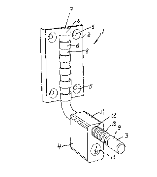
The invention will be explained in more detail below with reference to the one
2o accompanying figure. This figure shows in perspective a lockable hanging
appliance
according to the present invention.
The hanging appliance 1 comprises a bracket 2 and one outward oriented rod 3
connected to the bracket, plus a lock 4, which is aligned to be connected with
the rod 3.
2s The bracket 2 is a plate formed body, wherein a hole 5 is shaped, through
which can be
inserted screws, rivets or similar for fastening the bracket 2 for example to
a wall.
On the bracket 2 is modelled a number of protuberances 6, which every second
is
curved to the opposite side. These protuberances define a channel 7 that
expands all
3o along bracket 2. The procedure for modelling such protuberances is
described in detail
in PCT/N097/00080. It shall therefore not be explained in detail here.

CA 02285887 1999-10-15
4
The rod 3 consists of two main parts. A first part 8, which is received
rotatable in
channel 7, and a second part 9, which is connected in approximately at right
angle with
the first part 8 and when in use mainly protrudes at right angle from the
bracket's 2
level.
s
On the rod's 3 second part 9 are formed grooves, notches or similar, which
stretch along
a section of the second part 9.
The lock 4 comprises a locking case 11, through which a continuous hole 12 is
formed.
io In the locking case there is also mounted a conventional cylinder lock 13,
which in a
conventional way is equipped with a pawl mechanism (not shown), which can come
into engagement with the grooves or notches 10 within the hole 12.
The present hanging appliance is first and foremost intended for firm locking
of vehicle
is tyres or rim wheels to a wall. In such a case a wheel bolt hole or hub hole
on the rim
wheel can be threaded into the rod's 3 second part 9 so far that the wheel or
rim will
touch the wall. Thereafter the lock 4 is conducted into the rod 3's second
part 9 until the
locking case is touching the rim. The cylindrical lock 13 is then locked so
that the pawl
mechanism comes in gear with the grooves or notches 10.
zo
In a preferred design the grooves or notches 10 and the pawl mechanism are
adapted to
each other so that, by the help of corresponding sloping surfaces, the lock 4
can be
conducted along the rod's 3 second part 9 also after the locking cylinder 13
is locked.
The pawl mechanism and the grooves or notches 10 are, however, adapted to each
other
zs so that the lock 4 cannot be pulled along the rod's 3 second part 9 after
the locking
cylinder 13 is locked. With other words the pawl mechanism and the grooves or
notches
will work as a pawl and ratchet mechanism.
When the suspension hanger 1 according to the invention is not in use the rod
3 can be
3o swung towards the wall by the rod's 3 first part 8 rotates in the channel
7. The
suspension hanger can therefore be brought to a position where is will not be
in the way
nor expose persons to danger. The rod's 3 first part 8 is locked axially in
the channel 7,
for instance by a bulb (not shown).

CA 02285887 1999-10-15
If the bracket 2 is fastened to the wall with the help of conventional screws,
the
appliance which is to be locked preferably ought to have a form so that it
covers the
screws and make these inaccessible from the outside. In cases where the
appliance will
s not cover the holes 5, the bracket 2 ought to be fastened by the help of
fastening
arrangement which does not easily open, for instance rivets or so called one
way
screws, or a cover/disc is mounted which covers the fastening arrangements.
It is also conceivable to hang more than one item on the same suspension
hanger, for
io instance two or more vehicle tyres or rims. Two or more suspension hangers
can
according to the present invention also be used to lock up larger items, such
as for
example a bicycle.
Even if the suspension hanger specifically is described as a wall suspension
hanger, this
~s can of course also be attached to any other approximately vertical surface,
as for
instance the rear hatch of a vehicle.

Dessin représentatif
Une figure unique qui représente un dessin illustrant l'invention.
États administratifs

2024-08-01 : Dans le cadre de la transition vers les Brevets de nouvelle génération (BNG), la base de données sur les brevets canadiens (BDBC) contient désormais un Historique d'événement plus détaillé, qui reproduit le Journal des événements de notre nouvelle solution interne.

Veuillez noter que les événements débutant par « Inactive : » se réfèrent à des événements qui ne sont plus utilisés dans notre nouvelle solution interne.

Pour une meilleure compréhension de l'état de la demande ou brevet qui figure sur cette page, la rubrique Mise en garde , et les descriptions de Brevet , Historique d'événement , Taxes périodiques et Historique des paiements devraient être consultées.

Historique d'événement

Description Date
Inactive : CIB de MCD 2006-03-12
Le délai pour l'annulation est expiré 2005-10-17
Demande non rétablie avant l'échéance 2005-10-17
Inactive : Abandon.-RE+surtaxe impayées-Corr envoyée 2004-10-15
Réputée abandonnée - omission de répondre à un avis sur les taxes pour le maintien en état 2004-10-15
Lettre envoyée 2001-11-19
Exigences de rétablissement - réputé conforme pour tous les motifs d'abandon 2001-11-01
Réputée abandonnée - omission de répondre à un avis sur les taxes pour le maintien en état 2001-10-15
Inactive : Page couverture publiée 2000-04-16
Demande publiée (accessible au public) 2000-04-16
Lettre envoyée 2000-01-24
Inactive : Transfert individuel 1999-12-23
Inactive : CIB en 1re position 1999-11-26
Inactive : Lettre de courtoisie - Preuve 1999-11-09
Inactive : Certificat de dépôt - Sans RE (Anglais) 1999-11-08
Inactive : Demandeur supprimé 1999-11-05
Demande reçue - nationale ordinaire 1999-11-05

Historique d'abandonnement

Date d'abandonnement Raison Date de rétablissement
2004-10-15
2001-10-15

Taxes périodiques

Le dernier paiement a été reçu le 2003-09-23

Avis : Si le paiement en totalité n'a pas été reçu au plus tard à la date indiquée, une taxe supplémentaire peut être imposée, soit une des taxes suivantes :

  • taxe de rétablissement ;
  • taxe pour paiement en souffrance ; ou
  • taxe additionnelle pour le renversement d'une péremption réputée.

Les taxes sur les brevets sont ajustées au 1er janvier de chaque année. Les montants ci-dessus sont les montants actuels s'ils sont reçus au plus tard le 31 décembre de l'année en cours.
Veuillez vous référer à la page web des taxes sur les brevets de l'OPIC pour voir tous les montants actuels des taxes.

Historique des taxes

Type de taxes Anniversaire Échéance Date payée
Taxe pour le dépôt - petite 1999-10-15
Enregistrement d'un document 1999-12-23
TM (demande, 2e anniv.) - petite 02 2001-10-15 2001-11-01
Rétablissement 2001-11-01
TM (demande, 3e anniv.) - petite 03 2002-10-15 2002-09-18
TM (demande, 4e anniv.) - petite 04 2003-10-15 2003-09-23
Titulaires au dossier

Les titulaires actuels et antérieures au dossier sont affichés en ordre alphabétique.

Titulaires actuels au dossier
LENA SUNDHAGEN
Titulaires antérieures au dossier
GUNNAR SUNDHAGEN
Les propriétaires antérieurs qui ne figurent pas dans la liste des « Propriétaires au dossier » apparaîtront dans d'autres documents au dossier.
Documents

Pour visionner les fichiers sélectionnés, entrer le code reCAPTCHA :


Pour visualiser une image, cliquer sur un lien dans la colonne description du document. Pour télécharger l'image (les images), cliquer l'une ou plusieurs cases à cocher dans la première colonne et ensuite cliquer sur le bouton "Télécharger sélection en format PDF (archive Zip)" ou le bouton "Télécharger sélection (en un fichier PDF fusionné)".

Liste des documents de brevet publiés et non publiés sur la BDBC .

Si vous avez des difficultés à accéder au contenu, veuillez communiquer avec le Centre de services à la clientèle au 1-866-997-1936, ou envoyer un courriel au Centre de service à la clientèle de l'OPIC.


Description du
Document 
Date
(aaaa-mm-jj) 
Nombre de pages   Taille de l'image (Ko) 
Dessin représentatif 2000-04-06 1 7
Abrégé 1999-10-14 1 13
Description 1999-10-14 5 215
Revendications 1999-10-14 2 87
Dessins 1999-10-14 1 15
Certificat de dépôt (anglais) 1999-11-07 1 164
Courtoisie - Certificat d'enregistrement (document(s) connexe(s)) 2000-01-23 1 115
Rappel de taxe de maintien due 2001-06-17 1 112
Courtoisie - Lettre d'abandon (taxe de maintien en état) 2001-11-12 1 183
Avis de retablissement 2001-11-18 1 171
Rappel - requête d'examen 2004-06-15 1 116
Courtoisie - Lettre d'abandon (taxe de maintien en état) 2004-12-12 1 176
Courtoisie - Lettre d'abandon (requête d'examen) 2004-12-28 1 167
Correspondance 1999-11-07 1 14
Taxes 2003-09-22 1 30
Taxes 2001-10-31 1 38