Note : Les descriptions sont présentées dans la langue officielle dans laquelle elles ont été soumises.
CA 02286675 1999-10-08
WO 98/48855 PCT/US97/07633
MOISTURE SENSITIVE ITEM DRYING APPLIANCE
l3ackaround Of The Invention
Fie1_d Of The Invention
This invention concerns a drying appliance for
demoisturizing small items which come into contact with
the human body, e.g., with body cavities such as ear
canals, the mouth, or the like, and particularly concerns
items which are sensitive to moisture or bacteria such as
hearing aids, hearing aid or other batteries, custom
molded ear plugs and hearing protectors, tooth brushes,
medical devices or the like, and for storing such items
in a substantially dry and sanitized environment, whereby
the longevity of the item and its long term functionality
are markedly enhanced, and/or its sterilization is
effected. The invention particularly concerns such an
appliance which is readily transportable, self-contained,
and especially adapted for maintaining the operability
and sterile condition of moisture or bacteria sensitive
hearing aids and other small and intricate electrical or
electronic devices.
It is a common characteristic of electrical or
electronic devices or items, particularly where
electrical or electronic switching components, or
miniaturized batteries or the like are involved, for the
circuitry to become corroded, short circuited, chemically
attacked, or otherwise rendered less effective or
completely inoperable by contact of the item with
moisture, either from the ambient atmosphere, by
structure damaging accident o;r, as in the case of hearing
aids, from contact also with 'the user's moist body
tissues and the bacteria or fungi carried thereon, and by
ambient humidity which fosters, in particular, chemical
activity and bacterial growth. Also, and of marked
concern is the fact that external otitis (infection in
the ear canal) is a common malady for hearing aid users.
The insertion of a hearing aid or mold into the ear canal
reduces the ability of air to circulate causing increased
CA 02286675 1999-10-08
WO 98/48855 PCT/US97/07633
- 2 -
moisture in the canal and also produces ideal conditions
for bacteria development. In this regard, many hearing
air users utilize ear drops at night which dry the ear
canal and tend to keep it acidic in order to prevent or
reduce otitis. However, each day's insertion of a
hearing aid can reintroduce old bacteria or earmold from
the hearing aid back into the ear canal.
Desc_r,'_ption of the Prior Art
Heretofore, storage units for small electrical items
such as button type batteries, and solar powered hearing
aids have been developed as exemplified in U.S. patents:
5,129,546; 5,210,804; and Des. 333,385. While these
units are no doubt useful for their intended purposes,
they do not address the moisture problems discussed above
and are not capable of functioning in a truly effective
demoisturizing manner.
Objects Of The Invention
Objects, therefore, of the present invention are: to
provide an appliance means for demoisturizing moisture
sensitive items, and for storing the same under dry
conditions; to provide such appliance which is self-
contained and easily transportable; to provide such
appliance with structure which affords protection to the
item against damage while not in use and which also
affords a convenient and attractive storage facility
therefor; to provide such appliance in a structural form
which allows for easy assembly of the structural
components thereof, and thus its maintenance; to provide
such appliance with safety means comprising automatic
electrical switching means activated by proper placement
of essential components and items therein; and to provide
such appliance in a miniaturized form whereby it can be
easily carried in a handbag, small suitcase or the like.
CA 02286675 1999-10-08
WO 98/48855 PCT/US97/07633
Summary Of The Invention
These and other objects hereinafter becoming evident
have been attained in accordance with the present
invention through the discovery of certain structure for
an appliance for demoisturizing moisture sensitive items,
which structure, in its broad aspects, comprises housing
means formed by wall means and adapted to provide
substantially sealed chamber :means containing a
substantially singular quantity of gas, access port means
formed thru said wall means and providing access to said
chamber means, said wall mean:a providing removable
closure means for said port means for substantially
sealing said port means to gaa flow there through,
support or carriage means in raid chamber means for
carrying at least one moistures sensitive item therein
such as electronic hearing aids, toothbrushes, medicinal
preparations and devices, and the like, and also for
carrying desiccant means, regulating or control means for
said gas in said chamber means for heating and
maintaining a flow of said gas in a circulation path in
said chamber means, said support means being positioned
in said circulation path whereby the circulated gas will
come into contact with said dea iccant means and said item
in said chamber means for heating said gas to a
ta~perature which enhances evaporation of moisture from
said item without damaging said item or said desiccant
means.
In certain preferred embodiments:
(a) said support means comprises a first carriage
means for carrying at least one said item, and further
comprises a second carriage means for carrying said
desiccant means, said desiccant means substantially
divides said chamber means into first and second regions,
passage means is provided interconnecting said first and
second regions for providing a gas flow circulation path
CA 02286675 1999-10-08
WO 98/48855 PCT/US97/07633
- 4 -
there through, said circulation path comprising (a) gas
flow from said second region into contact with and
through said desiccant means, (b) then into and thru said
first region whereby said item is contacted with at least
partially desiccated air, (c) then thru said passage
means back into said second region, and (d) then again
into contact with said desiccant means to continue said
circulation;
(b) said gas moving means comprises fan means
mounted upstream of said desiccant means, and wherein
said heater means is mounted between said desiccant means
and said fan means, said fan means, desiccant means and
heater means all being within said circulation path;
(c) said desiccant means and its mounting provide a
substantially closed path for passage of circulating
heated gas into said first region;
(d) said first carriage means comprises flexible
net means having a contact area of less than about 10% of
the surface area of the portion of said item which is in
contact with said contact area;
(e) said support means is laterally displaced from
said passage means whereby a substantial amount of the
circulating gas moves into close proximity to said item;
(f) said desiccant means is removably carried by
said second carriage means such that it can be readily
replaced when its desired desiccating capacity is
depleted;
(g) locator means is provided on interior portions
of said housing means for functioning in cooperation with
said support means and control means to position the same
within said housing means;
(h) said support means is located within said first
region for supporting both said item and said desiccant
means therein in substantially the same horizontal plane;
CA 02286675 1999-10-08
WO 98/48855 PCT/US97107633
- F~ -
(i) sterilizing or germicidal means such as
ultraviolet generating lamp means or replaceable chemical
means such as alcohol or antibiotic containing, slow
release pads, or ejector means for atomizing or spraying
germicidal or anti-fungal material into the air flow
stream is provided within the circulation path;
(j) said support means is in the form of a drawer
means which can be easily slid in or out of the chamber
means through said port means thru said wall means of
said housing means;
(k) said heater means a:Lso functions as said fan
means by energizing the gas molecules to f low in an
upward direction toward said j=first region of said chamber
means;
(1) an electrical circu»t means is provided for
controlling operation of said heater means and said fan
means, and a safety switch is provided in said circuit
means, and a specially constructed drawer means is
provided as said support mean: for carrying said
desiccant means and/or said item, wherein said drawer
means and/or said desiccant means has a closing means for
said switch whereby said switch is closed only when said
drawer means and/or said desiccant means is properly
positioned within said chamber means whereby the
appliance can then be electrically energized, e.g., by a
manual on/off button; and
(m) said support means comprises a drawer means
provided with a first compartment for said item, and a
second compartment for said desiccant means, and
reflector means for W radiation is positioned in said
second compartment for focusing said radiation toward
said item.
The present appliance provides an attractive storage
space for hearing aids which are not in use, while
providing a drying and sterilizing environment for
CA 02286675 1999-10-08
WO 98/48855 PCT/US97/07633
- 6 -
reducing or eliminating moisture and, at the same time,
sterilizing the hearing aid, against earmold or the like.
The dry environment also dries cerumen (ear wax) which
coats onto the item, thus making removal of the cerumen
therefrom much easier. When a W lamp is employed, the
ozone produced acts as a deodorizer, while direct
irradiation of the item directly kills bacteria or the
like.
In a general embodiment, the present appliance
consists of a closed chamber with a miniature fan
circulating heated air which is passed directly over the
hearing aids. Situated anywhere within the chamber is a
desiccant which absorbs moisture, which desiccant is
easily removed when saturated and may be dried at a
higher temperature such as in an oven, and reused
repeatedly in the appliance. The chamber also preferably
contains a germicidal lamp which may be directed into the
air flow circulation path or directly onto the hearing
aid or other item, thereby sterilizing the surface of the
item as well as the circulated air. The heating element
preferably is controlled by a thermostat for maintaining
a constant temperature ideal for drying. An on/off
switch and an indicator lamp for all electrically
operated components may also be included. A special
drawer may be provided for convenient insertion and
removal of the item and/or the desiccant.
R_rief Description Of The Drawinas
The invention will be further understood from the
drawings herein of certain preferred embodiments, wherein
the structures are not drawn to scale, and the following
description thereof, wherein:
Fig. 1 is a longitudinal, vertical, cross-sectional
view of the appliance;
Fig. 2 is a lateral cross-sectional view taken along
line 2-2 of Fig. 1 in the direction of the arrows;
CA 02286675 1999-10-08
WO 98/48855 PCT/US97/07633
Fig. 3 is a top view of a preferred net form
embodiment of the item support means;
Fig. 4 is a cross-sectional view taken along line 4-
4 of Fig. 3 in the direction of the arrows;
Fig. 5 is a view taken along line 5-5 of Fig. 4 in
the direction of the arrows;
Fig. 6 is a view as in F'ig. 2 with the item support,
desiccant means, and heater means removed for clarity,
and with the housing means configured generally circular
1o in cross-section;
Fig. 7 is a view taken along line 7-7 of Fig. 1 in
the direction of the arrows;
Fig. 8 is a schematic of an electrical circuit
useful in the present appliance;
Fig. 9 is a side view of an item supported on a net,
the cords of which are shown in cross-section in order to
show the area "A" referred to herein;
Fig. l0 is a cross-sectional view as in Fig. 1
showing an alternative arrangement of the various
components of the appliance within the circulation path;
Fig. 11 is a view as in :figs. 1 and 2 showing a
variation in the carriages, i.e., a pull out drawer type
carriage means for carrying either of the items or
desiccant means;
Fig. 12 is a front view of the appliance employing
separate drawers for the item and desiccant;
Fig. 13 is a cross-sectional view taken along line
13-13 of Fig. Z2 with portion; broken away for clarity
and showing the desiccant drawer, i.e., the second
y 30 carriage or support means, provided with electrical
switching means for making or breaking one or more safety
or other electrical circuits of the appliance;
Fig. 14 is a partially cross-sectional view similar
to Fig. 13 of a unitary desiccant package and pull-out
drawer means of the present invention;
CA 02286675 1999-10-08
WO 98/48855 PCT/US97/07633
- g -
Fig. 15 is a cross sectional view taken along the
line 15-15 of Fig. 14;
Fig. 16 is an enlarged cross-sectional view taken
along line 16-16 of Fig. 15 and showing the drawer
biasing mechanism;
Figs. 17 and 18 are electrical circuit schematics
for controlling operations of the fan motor, the heater
means, germicidal lamp means, and safety and indicator
light means;
l0 Fig. 19 is a partially cross-sectional view showing
one preferred, single drawer arrangement of the
appliance;
Fig. 20 is a cross-sectional view taken along line
20-20 of Fig. 19 and showing a specialized drawer
arrangement for the item and desiccant and employing W
radiation focusing means;
Fig. 21 is a cross-sectional view of the drawer of
Fig. 20 taken along line 21-21 of Fig. 20;
Fig. 22 is a cross-sectional view of a variation of
the structure of Fig. 14 taken along line 22-22 thereof;
Fig. 23 is a top view of a variation of the item
carriage means of the drawer of Fig. 20; and
Fig. 24 is a cross-sectional view taken along line
24-24 of Fig. 23 with a W lamp shown in dotted outline.
Description of the Preferred Embodiments
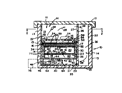
Referring to the drawings, particularly Figs. 1 and
2 and with particular reference to the claims hereof, the
present appliance in one preferred embodiment comprises
housing means generally designated 10 formed by wall
means generally designated 13 having an access opening or
port means 11 and a removable cap means 12 for providing
substantially sealed chamber means generally designated
14 and access thereto, support means generally designated
15 comprising, in this particular embodiment, a first
carriage means 22 for supporting an item, and a second
CA 02286675 1999-10-08
WO 98/48855 PCT/US97/07633
carriage means 114 for a desiccant means, said desiccant
means 16 comprising any moisture absorbing material such
as supported granular CaO, CaCl2, ZnCl2, CuS04, silica gel
or the like, panel means 17 mounted in said chamber means
and forming a passage means 26 therein, said first and/or
said second carriage means substantially dividing said
chamber means 14 into first 18 and second 20 regions,
openings 27 and 29 thru said ,panel means 17, which
openings in combination with the plurality of aperture
means 19 in first carriage means 22, and apertures 60 and
62 in second carriage means 114, interconnect said first
and second regions for providing a gas flow, e.g., air
flow circulation path genera lly designated 28 through
said chamber means, said circulation path comprising (a)
gas flow from said second region 20 into contact with and
through said desiccant means :16, (b) then into said first
region 18 for contact with said item, (c) then thru said
passage means 26 back into said second region 20, and (d)
then back into contact with said desiccant means 16 to
continue said circulation path, and gas moving means 30
mounted in said chamber means 14 for forcing and
maintaining said gas flow circulation path 28, and heater
means 36 mounted in said chamber means for heating said
gas.
The housing means 10 can be of any configuration and
material, for example, with a lateral cross-sectional
shape of square, rectangular, oval or round, and of
plastic, wood, ceramic or metal. As shown in Figs. 1, 2
and 6, the housing may consist. of an outer section 32 and
an inner section 34 which, preferably, is in the general
form of a removable cup 35. Mounted in the cup, or if
only section 32 is employed, mounted on the inner wall
portions and floor of the housing wall means 13, are the
components 22, 16, 30, and heater 36 which heater
preferably comprises a miniature electrical grid or
CA 02286675 1999-10-08
WO 98/48855 PCT/US97/07633
- 10 -
resistance heater wherein the spacings 21 between the
resistance wires 23 thereof allow air flow thru the
heater to continue the circulation path 28.
Cap means 12 may be threaded onto the housing wall
or dimensioned to provide a light friction f it which
allows its removal by simple hand twisting and pulling
force. This cap may be of any configuration and
dimension such as and including the front piece 87 of the
drawer type carriage means of Figs. 13 and 14, and may be
positioned anywhere on the housing. In this regard, a
top access port may be eliminated in embodiments wherein
the housing means is substantially permanently sealed and
accesses to the aforesaid components is provided thru one
or more access ports, e.g., thru a side of the housing
wherein the components are supported on drawer means such
as described below in regard to Figs. 13 and 14.
In the construction shown in Fig. 1, the cup sides
are provided with shoulder means 38 on which baffle plate
40 rests, said plate providing thru its circular opening
42 a portion of circulation path 28. The blade 44 of fan
preferably is mounted closely adjacent opening 42 such
that its air moving efficiency is maximized and back flow
wherein the desiccant means can be by-passed, is
minimized.
25 In the embodiment of Fig. 11 which illustrates the
drawer type support for the item and/or desiccant
components of the appliance, a first port means 96 and a
second port means 97 are formed thru the front wall of
the housing for receiving first carriage means 22 and
30 second carriage means 76 respectively. Each drawer 45,
as illustrated for the first carriage means 22 and also
for the second carriage means 76 comprises a floor means
51 having an adequate number of aperture means 53 there
through for allowing proper drying air flow thru the
carriage means. Each drawer preferably has a front piece
CA 02286675 1999-10-08
WO 98/48855 PCT/US97/07633
- 1:L -
55 affixed to or integrally formed therewith and provided
with handle means 57 such as ~~ recess formed therein for
being finger gripped for pulling the drawers out of the
chamber. The floor means 51 is slidable on support rail
means 66 affixed to each of the inner surfaces of
opposite sides 68, 70 of the dousing means and running
from front to back of the hou:~ing.
Referring to Figs. 13 and 15, the drawer means 45 of
this embodiment and comprising the second carriage means
76 can be constructed similarly to that of Fig. 11 and
comprises the apertured floor means 51, side walls 78 and
85, rear wall 98 and a modified front piece 87. This
front piece is adapted to substantially seal against
facing portions 88 of the front of the housing means 10
when the drawer is pushed thru the rectangular second
port means 89 in the front of the housing wall into the
chamber to its operative position as shown in Fig. 13,
i.e., the position where the operational safety
requirements of the appliance are satisfied, and switch
SW3 of Fig. 18 is closed. In this regard, sealing means
90 such as compressible polyurethane strip may be secured
all the way around the peripheral portions 95 of the
front piece to bear against the front facing portions 88
of the housing wall which define said port means and
thereby assist in preventing tine loss of desiccated air
from chamber 14 during the drying and storage of the
item, and thus preventing inopportune rehumidification of
the item.
Referring further to Fig. 13, this particular
embodiment of the desiccant means comprises a specially
constructed package or packet <.~1, e.g., of from about
0.25 to about 1.5 inches in the' thickness as shown in
Fig. 15 and enclosed by a fine mesh, coarse fabric or
plastic net material or the lil~:e 92 having openings 93
there through between the fibers or plastic strands or
CA 02286675 1999-10-08
WO 98/48855 PCTNS97107633
- 12 -
the like sufficient to readily allow air flow thru the
loose or matrix block shaped granular or powder desiccant
material 94 contained therein. While the packet is made
somewhat cushionable in this embodiment such that it can
be fairly tightly pushed down into the drawer cavity 115,
it is preferred that the packet be provided with
stiffening sides such as shown at 99 of plastic material
such as, e.g., 20-30 mil thick sheet of polypropylene,
cellulose ester, polyamide, or the like, such that the
packet can be pre-dimensioned to fit snugly against all
sides or walls 78, 85, 98 of the drawer and remain so
during its life, i.e., while it is still effective for
the dehumidification.
In this regard, and with respect to providing the
appliance with an electrical safety mechanism, and
referring further to Figs. 13 and 18, safety switch SW3
comprises, in one embodiment, a metal contact strip 100
which is also termed herein as a switch closure means, is
adhesively or otherwise affixed to any surface portion of
the desiccant packet, preferably to a side thereof as
shown as 99. A pair of electrical contacts 101 and 102
are mounted thru a side such as 85 of the drawer and
extend a short distance beyond its inside surface 103
such that strip 100 will slide on the contacts but firmly
make an electrical connection between the contacts as the
packet is placed into its operative position in the
drawer as shown in Fig. 13. With the electrical
connection thus made, the drawer can then be pushed into
the housing thru the second port means 89 to the position
shown in Fig. 13 such that the outer ends 104 and 105 of
contacts 101 and 102 respectively make electrical contact
with terminals 106 and 107 respectively as indicated in
Fig. 13 to thereby place the electrical circuit in
readiness. These terminals are electrically connected
into the circuit of Fig. 18 by suitable leads 112, 113
CA 02286675 1999-10-08
WO 98/48855 PCT/US97/07633
- 13 -
shown in Fig. 18. In order to assist in proper drawer
placement, the inner or rearward corner 108 of the drawer
is beveled to allow it to readily slide over the
terminals. In order to urge side wall 85 of the drawer
and said contact ends 104 and 105 toward the terminals,
one or more biasing means suclh as spring 109 mounted on
the housing wall as shown in more detail in Fig. 16 may
be employed. This spring, when flexed inwardly by the
drawer wall can partially retreat into a cavity 110 in
the housing wall as shown by dotted line in Fig. 16 and
maintain a sufficient lateral force on the drawer to
insure good contact of ends 104 and 105 with said
terminals.
Referring to Figs. 14 anc~ 15, the desiccant packet
and drawer means comprise a unitary desiccant unit
generally designated 111 and is of the same general
structure as packet 91 with equivalent structure numbered
the same. This unit however, is preferably provided with
somewhat more rigid structure than the packet 91 since
the unit functions also as the: second carriage means or
drawer. To this end, the front wall of packet 111 may be
affixed to the rigid front piece 87 by adhesive or the
like, and the sides 99 and rear wall 98 of the packet are
thickened, e.g., 0.125 in., and made fairly rigid such as
to reduce lateral distortionability of the unit.
In this embodiment of Fig. 14, the biasing springs
109 are not employed to bias the drawer, but rather to
serve as the terminals 106 and 107 such that a firm
electrical connection between 'the contact strip or switch
closure means 100 and said terminals is made and
maintained when the desiccant packet is pushed inwardly
thru port 89 to its operative ~gosition shown in Fig. 13.
It is noted that equivalent swatch devices can be placed
at practically any position on either or both of said
first or second carriage means and adjacent housing
CA 02286675 1999-10-08
WO 98/48855 PCT/US97/07633
- 14 -
portions such that the electrical system of the appliance
cannot be actuated, e.g., by a hand operated push button,
toggle, or voltage change responsive touch type switch
until both of said carriage means, or at least the
desiccant means is in its operative position in chamber
14.
Referring further to Fig. 15, the concept is
illustrated of employing the desiccant unit 111 also as
the first carriage means whereby the items 24 may rest
directly on the upper fabric surface 116 of the desiccant
unit or on a highly porous fabric cushion or basket or
the like, such as the radiation reflective cup means of
Figs. 23 and 24 hereinafter described in detail and
positioned on said upper surface 116. In this embodiment
the port means for the desiccant unit must be made of
sufficient height dimensions as to allow the carriage
means to slide in and out there through without causing
contact of the items with the housing portions forming
the top edge of the port means.
In all of the embodiments of the desiccant means
described herein, and particularly those of Figs. 13 and
14, the desiccant means itself may be provided with an
indicator means such as a humidity sensitive patch
located on a visible portion thereof which, e.g.,
undergoes a change in color, e.g., pink to blue as the
desiccant material progressively loses its effectiveness.
In this regard, it is preferred that said material be of
a type and form which can be readily refurbished or
regenerated by moderate heating, e.g., in a household
oven for a period of, e.g., one or two hours. Such
useful desiccants are market available as shown in the
brochure entitled "MULTIFORM DESICCANTS", ~1996, of
Multisorb Technologies, 325 Harlem Road, Buffalo, N.Y.
14224-1893, which brochure is hereby incorporated herein
by reference.
CA 02286675 1999-10-08
WO 98/48855 PCT/US97/07633
- 15 -
In one particular embodiment wherein the appliance
is to be used to sanitize special items which require
treatment with special chemicals or other germicidal
materials other than or in addition to UV radiation and
dehumidification, a syringe needle penetrable gland
element such as 97 of elastom~eric material, or other
closure structure, including .3 removable stopper means or
the like, is provided in the housing wall at any location
such that a hypodermic syringe or other ejector device
can be used to spray, inject or atomize said materials
into the gas flow stream.
Referring to Figs. 17 and 18, a preferred electronic
circuit for operating the present appliance can be seen
as four distinct sections: power supply, lamp driver,
fan/heater and control components.
Power Supply:
The power supply is a 117VAC to 15VDC unregulated
supply including components T7., D1, D2, C2 and R7. All
portions of the circuitry have: been protected via fuse
F1.
Lamp Driver:
When activated, IC3 provides AC power. Components
C1, Q1, R1 are used to both start and run a low power
fluorescent lamp. The lamp is. at a remote location and
tied to the printed circuit board via connector J2.
Fan/Heater:
When activated, IC2 provides AC power for both the
fan and the heating element R2. The heating element is
used to quickly bring the dryer to, e.g., a 35 degree
Celsius operating temperature. It is noted that this
circuit can be adjusted to give any desired temperature
range and any desired operating cycle or period to the
heater and to the fan. When operating temperature is
attained, thermal switch SW1 opens turning off the
heating element. It for any reason the temperature drops
CA 02286675 1999-10-08
WO 98/48855 PCT/US97/07633
- 16 -
below about 30 degrees Celsius or any other such desired
low point, the heating element is reactivated. Since the
fan is mounted remote, connector J1 is used to tie the
fan to the printed circuit board. Preferably, the fan
runs whenever the dryer is in operation.
Control:
ICI, a dual timer, provides timing functions for
both IC2 and IC3, plus control of start and safety stop.
Components R11, C6, C5 with ICI provide for the overall
length of time the dryer is to be active. R3 and IC2, a
solid state relay, provide isolation between the AC power
and control circuits. They also provide power control
for the fan/heater circuit. R6 and D4, a light emitting
diode are used to indicate the dryer is functioning.
This diode can be placed at any desired location within
or on the housing such that it is readily visible to the
user. Components R8, R9, C3 and C4 with ICI provide the
on cycle and duration of the W lamp. R4 and IC3,
another solid state relay, provide isolation and control
for the W lamp circuit. R5 and D3 indicates when the UV
lamp is lit. Components R12 and SW2 start the timing
functions when SW2 is depressed. Components R12 and SW3
stop all functions and remove power from the W lamp and
fan if the dryer is opened. Switch SW3 is at a remote
location and is tied to the printed circuit board using
J3.
It is noted that such structural features as herein
described are important to the preferred embodiments of
the present invention in that the miniature sizes and
powers of the components employed require conservative
engineering in order to be efficient in the very limited
spaces available for them. In this regard, a useful set
of operating parameters for an electrically operated fan
30 and heater 36 are that the fan motor and the heater
preferably can operate from either a permanent power
CA 02286675 1999-10-08
WO 98/48855 PC1'/US97/07633
1-~
source such as above described or from a three to six
volt battery for about 30 minutes, with an airflow of
from about 10 to about 50 cu._Ln./min., and a heat output
of from about 0.5 to about 5.0 calories/min. Should such
be desired, a solar panel dev~~_ce may be mounted on sun-
exposed portions of the housing to generate sufficient
electricity to recharge batteries or to directly power
the fan and/or heater.
Such warmed, desiccated air-flow generally will
satisfactorily dry a moist electronic item. Thereafter,
the battery 46 can be recharged by any known and suitably
reduced voltage power means th.ru, e.g., electrical prong
and socket access port 48. Th.e aforesaid operating
parameters can, of course, be widely varied as also may
the type and power consumption and output energies of the
fan and heater and the voltage and operating life of
their power supply. It is particularly noted that the
type of heater which may be employed includes the
chemical heater pack type which can be activated when
desired and placed within the lower cavity 64. Such
heating packs are typified by boot type warmers typically
employing iron powder, water, 'vermiculite, activated
charcoal and salts which, when exposed to oxygen within
the contained package will chemically react and stay
warm, e.g., about 100°F for several hours. For such a
heating means, access port 48 may comprise a laterally
elongated slot provided with a suitable cover whereby the
chemical pack can be inserted :into and removed from
cavity 64.
In the embodiment shown in Fig. 1, each component
36, 16, and 22 is provided with its own peripherally
surrounding base means 50, 52 and 54 respectively which
can be readily slid down into and stacked into cup 35.
One or more screws such as 56 or other fastening means
may be provided to fix base 54 to the cup side to thereby
CA 02286675 1999-10-08
WO 98/48855 PCT/US97/07633
- 18 -
maintain the relative positions of all of the said
components within the housing. It is noted that the
support component 22 can actually be part of the top 58
of the desiccant means 16 within the scope of the
terminology of the broad claims herein, in which case,
screw 56 could be used alternatively in conjunction with
base means 52. With such a stacking arrangement within
cup 35, all of the components are rendered readily
accessible for replacement or repair, e.g., replacement
of the desiccant material simply by sliding the cup out
of the outer section 32 of the housing, removing screw 56
and then lifting the components out of the cup. In this
regard, the desiccant material is preferably carried in a
module shell 59 comprising bottom plate 61 and top plate
58 having a sufficient number of inlet apertures 60 and
outlet apertures 62 respectively to allow proper flow of
recirculating air thru the desiccant.
Referring to Figs. 7 and 8, the battery 46 and motor
30 may be attached to each other in any suitable manner
and affixed in position on the floor 37 of cup 35 by a
strong and essentially inflexible bracket or clip 63, the
ends 65 of which are pushed into tight fitting recesses
67 in the wall of section 32, and the nib 69 of which is
inserted into recess 71 in the motor shell. With this
construction, or with any equivalent construction, the
motor and battery can be conveniently secured, but
removably so, at a proper position in the appliance.
A useful electrical circuit is shown schematically
in Fig. 9 and in enlarged Fig. 8 wherein the connection
of the battery to the motor, and of the battery to a
charging unit 75 is made by plug in type connectors 73,
and a push type, on/off switch 77 is mounted in wall 32,
preferably f lush with or inset from the outer surface of
said wall for avoiding inopportune activation of the
appliance during travel or the like. If desired, a
CA 02286675 1999-10-08
WO 98/48855 PCT/US97/07633
- 19 -
second such switch 79 may be provided for the heater
circuit such that the air circulation can proceed
independently of heating the air. For extended periods
of residency of the item in the appliance, this feature
is very advantageous. It is noted that in situations
where electrical power is available, the charging unit 75
and battery 30 may be replaced by a transformer device
such that, e.g., normal house current may be used, in
reduced voltage, to power the motor and heater. In this
regard, the fan motor and elecarical heater may be
constructed to operate on hou:~e electrical power, e.g.,
110 V, where, e.g., use of the: appliance is to be only
where such power is available.
The gas flow or circulation path 28 is initiated and
maintained by gas moving mean: comprising either or both
of fan 30 or heater 36. Where: the residence time of the
hearing aid in the appliance is, e.g., overnight, then
the heater by itself will effect sufficient air flow
upwardly thru the desiccant and cause sufficient air
recirculation to subject the hearing aid to a
continuously and sufficiently demoisturized gas flow to
demoisturize the same. The obviously preferred gas is,
of course air, however, for certain items which, e.g.,
may be prone to oxidation, a singular quantity, i.e.,
trapped amount of recirculatin~g gas such as Helium may be
injected by suitable means int~a the capped chamber and
the air flushed therefrom and 'then resealed, whereby the
Helium acts as the moisture pi~~k-up medium.
A germicidal means such a:~ a W lamp 72 is
preferably provided in any pori~ion of the chamber means
for purifying the recirculatinc~ air and the item.
Suitable battery or house currE~nt electrical contact
means 74 may extend through then housing wall for plug-in
type, separate electrical connection. However, it is
highly preferred that the lamp circuit be integrated into
CA 02286675 1999-10-08
WO 98/48855 PCT/US97/07633
- 20 -
the overall appliance circuit such as shown in Figs. 17
and 18. Such useful germicidal lamps and their
specifications are described in the 16 page General
Electric, Large Lamp Department publication, TP-122,
October, 1970.
The net form construction 80 of the item support or
carriage means as shown in Figs. 3-5 may be of any
natural or synthetic material, but preferably of fine
denier cotton, silk, rayon or the like. This
construction insures that the item will be essentially
totally exposed to dry air flow since the netting covers
only a minuscule surface area of the item. In this
regard, such a small contact area, e.g., less than about
10 o and preferably less than about 2% or less of the
"total area" of the item surface which is substantially
laterally covered by the cord 81 of the support means,
and the nearly complete lack of mass of the netting
cords, eliminates any formation of hot spots which might
otherwise and damage the same.
The aforesaid total area is the aggregate of the
areas "A" of the contacting cords which may be of
dimensions and strengths such as that of heavy duty
sewing thread. In a preferred form of the net, one or
more pocket means generally designated 82 are formed
therein, e.g., by stitching around the periphery of the
pocket as at 83 or hot forming of, e.g., the polyester or
Nylon thread, to receive the item, and preferably are
provided with a cover portion 84 stitched or adhesively
secured as at 85 around the pocket means and shaped to
provide an access opening 86 through which the item can
be passed. It is noted that the net type of construction
for the pocket means 82 and cover portion 84 readily
allows the netting to be flexibly expanded around the
opening 86 for facilitating entry and removal of the item
into and from the pocket and then closing slightly to
CA 02286675 1999-10-08
WO 98/48855 PCT/US97/07633
- 2.L -
secure the item therein. It .is noted further that this
net type of support provides considerable anti-shock
safety for the item should the appliance be jostled about
when being transported, or knocked from a night table, or
the like.
Referring to Fig. 10 wherein the identical or
equivalent structures of Fig. 1 are numbered the same,
the demoisturizing appliance comprises housing means 10
having removable cap means 12 for providing substantially
sealed chamber means 14 and access thereto, desiccant
means 16 mounted in said chamber means, support means 22
in a first region 18 in said chamber means for supporting
at least one moisture sensitive item 24 therein, and gas
moving means 30 in said chamber means for forcing and
maintaining gas flow circulation in said chamber means
and into contact with said desiccant means and said item,
said circulation path comprising gas flow into contact
with and through said desiccant means, then into and thru
a first region 18 whereby said item is contacted with at
least partially desiccated air, then into and thru a
second region 20, and then again into contact with said
desiccant means to continue said circulation.
In this embodiment, the grid heater 36, if a heater
is to be employed, is supported by a plurality of members
such as 31 which are secured ait one end to the housing
inner wall 25 and extend in a apider fashion radially
inwardly to provide support end portions 33 for the
heater. The desiccant means 16 may be of annular
configuration with its radially outer periphery 39
affixed to wall 25, or the desiccant means may comprises,
e.g., a plurality of arc-like segments affixed to wall
25. Referring to the embodiment of support means 22 of
Fig. 10, a plurality, e.g., four circumferentially spaced
hanger members 41 are affixed at their upper ends 43 to
cap 12 and are secured at their lower ends 49 by adhesive
CA 02286675 1999-10-08
WO 98/48855 PCT/US97/07633
- 22 -
or other means to a basket shaped net 45, the sides 47 of
which extend upwardly a selected and sufficient distance
to retain the items to the extent desired while allowing
easy finger access thereto for entry into and removal
from the support.
It is noted that region 18 is shown generally by
dotted single outline, and region 20 is shown generally
by dotted double outline. These regions are, of course,
variable in scope, configuration, and location within
said chamber means and within the context of the present
invention, as are the particular locations and dimensions
of the various components.
Referring to Figs. 19-21 wherein structures
equivalent to those previously described are numbered the
same, the fan 30 is suspended in or under opening 42 in
baffle plate 40 by means of one or more spider arms 117
affixed to the plate and the fan motor housing 118.
These arms 117 are spaced apart circumferentially to
allow plenty of space for the flow of gas upwardly thru
the fan blades 119. In this embodiment, the W lamp 72
is suspended from the inside of a hinged cover 120 such
that when the cover is swung open around hinge means 121,
the drawer or support means 45 for both the desiccant and
items is fully exposed such that the items and desiccant
can be easily installed or removed. The hinge means is
preferably spring biased such that it continually urges
the cover 120 to its closed position to ensure that the
desiccant is protected against excessive atmospheric
humidity due to unintentionally leaving the access port
11 open. Sealing cushion 90 secured either to the cover
or housing wall assists in sealing port 11 and eliminates
any thump should the cover 120 be allowed to spring
closed.
In this embodiment, the desiccant packet and general
structure of the drawer means, and the electrical contact
CA 02286675 1999-10-08
WO 98/48855 PCT/US97/07633
_ 2 ~~ _
circuitry may be as shown in F'ig. 13. The item carriage
portion of the drawer is preferably provided with
reflective coated side sections 122, 123 and center
section 124. These sections may be plastic sheet coated
with aluminum, tin, or any other reflective material by
adhesive means, metal vapor deposition, or the like.
These sections assist in focusing extraneous W radiation
onto the item.
In Fig. 22, a variation of the desiccant carriage
l0 means 76 is provided with a pull-out tab 126 and a spring
biased pull down door 128. The desiccant in this Figure
is granular silica gel bound into a highly porous block
shape by a shrink wrap of polyolefin having a large
number of holes 130 there through for allowing easy
25 passage of air thru the granular desiccant.
Referring to Figs. 23 and 24, the radiation
reflective means is shown as c~~up means 132 having a
conical configuration with its side 134 coated with
reflective metal or ceramic 135 on its inside surface.
20 The bottom 138 of the cup may loe configured with a tailor
made pocket 14o for holding the item in any desired
posture whereby the irradiation thereof is enhanced.
Spider arms such as 142 conneci~ side 134 and bottom 138
while providing sufficient spaces 144 for adequate gas
25 flow to the items from between the carriage strands I46
or ribs.
The invention has been de:~cribed in detail with
particular reference to preferred embodiments thereof,
but it will be understood that variations and
30 modifications will be effected with the spirit and scope
of the invention.