Sélection de la langue

Search

Sommaire du brevet 2287868 

Énoncé de désistement de responsabilité concernant l'information provenant de tiers

Une partie des informations de ce site Web a été fournie par des sources externes. Le gouvernement du Canada n'assume aucune responsabilité concernant la précision, l'actualité ou la fiabilité des informations fournies par les sources externes. Les utilisateurs qui désirent employer cette information devraient consulter directement la source des informations. Le contenu fourni par les sources externes n'est pas assujetti aux exigences sur les langues officielles, la protection des renseignements personnels et l'accessibilité.

Disponibilité de l'Abrégé et des Revendications

L'apparition de différences dans le texte et l'image des Revendications et de l'Abrégé dépend du moment auquel le document est publié. Les textes des Revendications et de l'Abrégé sont affichés :

  • lorsque la demande peut être examinée par le public;
  • lorsque le brevet est émis (délivrance).
(12) Demande de brevet: (11) CA 2287868
(54) Titre français: DISPOSITIF DE RESTRUCTURATION POUR ELECTRODE DE SOUDAGE
(54) Titre anglais: WELDING ELECTRODE RESHAPING DEVICE
Statut: Réputée abandonnée et au-delà du délai pour le rétablissement - en attente de la réponse à l’avis de communication rejetée
Données bibliographiques
(51) Classification internationale des brevets (CIB):
  • B23K 11/30 (2006.01)
(72) Inventeurs :
  • DI ROSA, GAETANO (Italie)
  • CAPPA, SERGIO (Italie)
  • ROSSI, CRISTIANO (Italie)
(73) Titulaires :
  • FATA AUTOMATION S.P.A.
(71) Demandeurs :
  • FATA AUTOMATION S.P.A. (Italie)
(74) Agent: SMART & BIGGAR LP
(74) Co-agent:
(45) Délivré:
(22) Date de dépôt: 1999-11-01
(41) Mise à la disponibilité du public: 2000-05-11
Licence disponible: S.O.
Cédé au domaine public: S.O.
(25) Langue des documents déposés: Anglais

Traité de coopération en matière de brevets (PCT): Non

(30) Données de priorité de la demande:
Numéro de la demande Pays / territoire Date
MI 98 A 002444 (Italie) 1998-11-11

Abrégés

Abrégé anglais


A welding electrode dressing device in particular in
automated welding stations comprises an electrode treatment
head (11, 111) equipped with upsetting members (15, 115)
which reshape the tip of an electrode inserted in it
without removing material. Advantageously the treatment
head (11, 111) comprises two treatment seats (19, 119)
arranged on opposite sides thereof to each receive the end
(12) of a pair of welding gun electrodes.

Revendications

Note : Les revendications sont présentées dans la langue officielle dans laquelle elles ont été soumises.


8
CLAIMS
1. Welding electrode dressing device in particular in
automated welding stations and comprising an electrode
treatment head (11, 111) equipped with upsetting members
(15, 115) which reshape the tip of an electrode inserted in
it without removing material.
2. Device in accordance with claim 1 characterized in that
the treatment head (11, 111) comprises two treatment seats
(19, 119) arranged on opposite sides thereof to each
receive the end (12) of an electrode of a pair of
electrodes of a welding gun.
3. Device in accordance with claim 1 characterized in that
the upsetting members comprise three satellites (15, 115)
with periphery (17) shaped for the desired upsetting and
arranged with rotation axis (18) at the vertices of an
equilateral triangle with the three satellites (15, 115)
being supported on a satellite holder (20) rotated by a
motor (14, 114) with the mutually facing parts of the three
satellites (15, 115) defining an upsetting seat for the
electrode tip.
4. Device in accordance with claim 1 characterized in that
it comprises another treatment head (125, 225) with tool
(126, 226) for cleaning the ends of electrodes brought into
contact therewith.
5. Device in accordance with claim 4 characterized in that
the cleaning tool comprises at least one rotating abrasive
disk (126, 226).

9
6. Device in accordance with claim 4 characterized in that
the cleaning tool comprises two parallel disks (226a, 226b)
mounted in such a way as to slide on a rotation shaft (240)
between the two disks with there being a thrust spring
(241) to provide a sprung sliding support for the two
disks.
7. Device in accordance with claim 1 characterized in that
it comprises a ground support (113) arranged in an
intermediate position between the treatment motor and head
(111).
8. Device in accordance with claim 1 characterized in that
it comprises a ground support (113) with sprung support
means (130).
9. Device in accordance with claim 7 characterized in that
the sprung support means (130) comprise pins (131)
constrained to the device body (136) and running in seats
(135) in the support (113) with there being fitted on each
pin mutually opposing thrust springs (133, 134) between
ends of the respective pin and support (113) to supply a
2-way sprung support.

Description

Note : Les descriptions sont présentées dans la langue officielle dans laquelle elles ont été soumises.

CA 02287868 1999-11-O1
1
"Welding electrode reshaping device"
The present invention relates to a device for dressing
welding electrodes and in particular in automatic welding
stations.
It is known that the electrodes which make contact with the
sheet metal to be welded are the consumable part of a
resistance welding system. For reasons of conductivity and
contact resistance the electrodes must be made of nearly
pure copper which is well known to be a ductile and
malleable material. During use the electrodes are subject
cyclically to high pressures with high temperatures and
undergo a plastic deformation process which changes their
shape to the detriment of welding quality. To limit
deterioration of quality beyond acceptable limits in
practice devices termed electrode dressers which
periodically mill the upset material with small shaped
milling cutters to restore the original shape of the
electrode tip are used.
Since the dressers work by material removal they can only
intervene a small number of times. The dressing operations
are therefore spaced in time and between one operation and
the next the quality of the welding tips undergoes
progressive deterioration to the limit of acceptability.
However, the dressers removing material shorten
considerably the useful life of the electrodes with
resulting increase in operating costs.
The general purpose of the present invention is to overcome
the above mentioned drawbacks by making available a

CA 02287868 1999-11-O1
2
dressing device which could be used frequently with optimal
results and without limiting the useful life of the
electrodes.
In view of this purpose it is sought to provide in
accordance with the present invention a device for welding
electrode dressing in particular in automated welding
stations and comprising an electrode treatment head fitted
with upsetting members which reshape the electrode tip
inserted in it without removing material.
To clarify the explanation of the innovative principles of
the present invention and its advantages compared with the
prior art there are described below with the aid of the
annexed drawings possible embodiments thereof by way of
non-limiting examples applying said principles. In the
drawings:
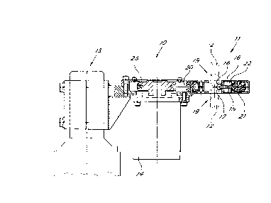
FIG 1 shows a diagrammatic side view partially cross
sectioned along plane of cut I-I of FIG 2 of a device in
accordance with the present invention, and
FIG 2 shows a plan view of the device of FIG 1,
FIG 3 shows a side elevation view cross sectioned along
plane of cut III of FIG 4 of a possible variant of the
device in accordance with the present invention,
FIG 4 shows a plan view cross sectioned along plane of cut
IV-IV of FIG 3, and
FIG 5 is a scrap view of another variant of the device of
FIG 3.
With reference to the FIGS FIG 1 shows a reshaping device
indicated as a whole by reference number 10 comprising a
treatment head 11 for dressing electrodes 12 of a robotized

CA 02287868 1999-11-O1
3
welding gun. The gun is not shown nor described here since
it is essentially prior art. This gun can be part of an
automated welding station where a plurality of robotized
arms perform processing on an object such as for example an
automobile body. The device 10 is supported by a support
13 appropriately arranged in the station so that the
robotized arms can carry the electrodes and grasp the
treatment head on the two sides.
An electric motor 14 drives upsetting members 15 located in
the treatment head to do the electrode tip upsetting by
exploiting the malleability and ductility of the material
making up the electrodes. The upsetting members have a
shape such as to define an upsetting seat 16, 17 for each
electrode of the gun with the seat being shaped as desired
for the electrode tip.
As may be seen also in FIG 2 in the embodiment described
the upsetting members are made in the form of three
satellites 15 with periphery shaped with seats 16 and 17.
The satellites are arranged with rotation axis 18 at the
vertices of an equilateral triangle to face each other
opposite an opening 19 for introduction of the electrode
tip in the reshaping device. The satellites 15 are
supported by means of their own plain bearings 22 by a
satellite holder 20 having bearings 21 supporting the body
of the device.
The satellite holder 20 is rotated by the motor 14 by means
of a drive belt 23.
In use after a predetermined number of welds or even a
single weld the welding gun closes on the head 11 so as to

CA 02287868 1999-11-O1
4
arrange the electrodes with the tips as shown in FIG 1.
Rotation of the satellite holder and consequently of the
satellites around the electrode tips perform the upsetting
of the tips to reshape them in the original shape. It
should be noted that the flat shape of the upsetting head
11 makes it perfectly compatible with the normal openings
of welding guns.
FIG.3 shows a second embodiment of a device in accordance
with the present invention. For the sake of convenience
details similar to those of the above embodiment are
indicated by the same numbering increased by 100.
The device of FIG 3 indicated as a whole by reference
number 110 comprises a treatment head 111 for dressing the
electrodes 12 and is supported by a support 113.
Differently from the device 10 the device 110 is supported
in an intermediate position between its ends with the motor
114 arranged overhanging on the side opposite the treatment
head. The motor 114 drives through a belt 123 upsetting
members 115 located in the head 111.
The upsetting head 111 is essentially similar to the head
11 described above to perform upsetting of the electrodes
inserted in an opposing manner therein through the openings
119.
Advantageously as may by seen in FIG 3 the support for the
device 110 is sprung by means of a spring units 130 and
comprises pins 131 integral with the body 136 of the device
110 and running in seats 135 made in a plate 132 of the
support 113. On the two sides of the plate 132 are located
springs 133, 134 each reacting between one end of the

CA 02287868 1999-11-O1
respective pin and the plate itself so as to provide a 2-
way elastic support in the direction of thrust of the
electrodes against the device. This elastic support allows
the device to move adequately under the thrust of the
5 welding guns which are brought into contact with the two
processing heads.
In addition to the upsetting head 111 the device 110 has a
second processing head or cleaning head indicated generally
by reference number 125. This second head 125 comprises a
tool 126 designed for performing surface cleaning with
negligible material removal. The tool is powered by the
motor 114 through a second belt 127.
The tool can be for example in the form of a lightly
diamond-coated abrasive or some other tool suitable for the
purpose for example with an appropriate cutting edge.
As may be seen in FIG 4 the tool 126 projects from a
protective hood 128 through an opening 129 so that the pair
of electrodes 12 of one gun can rest on the work surface of
the tool 126.
Thus it is possible to perform cleaning of the electrode
end which is a slightly flattened area (termed 'lens')
remaining despite the action of the reshaping rollers. In
this area are fixed oxides, zinc slag and the like which
alloy with the metal of the electrodes and reduce passage
of electrical current with resulting reduction of weld
quality.
Advantageously the tool can be configured to maintain a
slight curvature of the lens. This can be easily obtained

CA 02287868 1999-11-O1
6
with a tool shaped from a soft 'floating' disk or from a
brush.
Bearing of the disk tool can take place first for one
electrode and then for the other or simultaneously for both
electrodes by partial closing of the gun on the disk. In
the latter case it is necessary to check the gun closing
force to have the right pressure necessary for smoothing.
FIG-5 shows a variant of the smoothing head indicated as a
whole by reference number 225. In this variant the head
225 comprises two cleaning disks 226a, 226b mounted and
keyed in a running manner on a shaft 240 rotated by the
belt 127. Between the two disks is arranged a spring 241
which pushes them apart.
The two electrodes draw near to the two disks from opposite
directions and each electrode rests on the work surface of
one of the two disks.
Support can take place first for one electrode and then for
the other or simultaneously by partial closing of the gun.
The support force of the electrode on the disk is
determined by the spring 240. It is thus easy to supply a
predetermined support force even allowing for the
variability of positioning of the electrode tip which also
depends on consumption of the electrode due to welding
work.
It is now clear that the preset purposes have been
achieved. As no material is removed the possible number of
operations on one electrode is theoretically unlimited and
at each welding cycle the electrode appears practically
like new with assured quality for the entire cycle. The

CA 02287868 1999-11-O1
7
useful life of the electrodes is considerably prolonged
with considerable cost savings.
Even using the cleaning head, material removal is
negligible since this head basically only removes the
superficial oxides and does not reshape the electrode.
As another advantage, with assurance of welding tip quality
it will be possible to reduce the quantity of redundant
tips normally applied to the object being welded with
resulting advantages in production times and costs.
Lastly, no chips which must be removed from the processing
area are produced.
Naturally the above description of embodiments applying the
innovative principles of the present invention is given by
way of non-limiting examples of said principles within the
scope of the exclusive right claimed here.
For example shapes and proportions of component parts of
the device can vary with specific needs.

Dessin représentatif
Une figure unique qui représente un dessin illustrant l'invention.
États administratifs

2024-08-01 : Dans le cadre de la transition vers les Brevets de nouvelle génération (BNG), la base de données sur les brevets canadiens (BDBC) contient désormais un Historique d'événement plus détaillé, qui reproduit le Journal des événements de notre nouvelle solution interne.

Veuillez noter que les événements débutant par « Inactive : » se réfèrent à des événements qui ne sont plus utilisés dans notre nouvelle solution interne.

Pour une meilleure compréhension de l'état de la demande ou brevet qui figure sur cette page, la rubrique Mise en garde , et les descriptions de Brevet , Historique d'événement , Taxes périodiques et Historique des paiements devraient être consultées.

Historique d'événement

Description Date
Demande non rétablie avant l'échéance 2005-11-01
Le délai pour l'annulation est expiré 2005-11-01
Inactive : Abandon.-RE+surtaxe impayées-Corr envoyée 2004-11-01
Réputée abandonnée - omission de répondre à un avis sur les taxes pour le maintien en état 2004-11-01
Lettre envoyée 2004-05-13
Exigences de rétablissement - réputé conforme pour tous les motifs d'abandon 2004-04-30
Réputée abandonnée - omission de répondre à un avis sur les taxes pour le maintien en état 2003-11-03
Inactive : Lettre officielle 2001-12-05
Demande publiée (accessible au public) 2000-05-11
Inactive : Page couverture publiée 2000-05-10
Inactive : CIB en 1re position 2000-01-19
Lettre envoyée 1999-12-02
Inactive : Certificat de dépôt - Sans RE (Anglais) 1999-12-02
Demande reçue - nationale ordinaire 1999-11-26

Historique d'abandonnement

Date d'abandonnement Raison Date de rétablissement
2004-11-01
2003-11-03

Taxes périodiques

Le dernier paiement a été reçu le 2004-04-30

Avis : Si le paiement en totalité n'a pas été reçu au plus tard à la date indiquée, une taxe supplémentaire peut être imposée, soit une des taxes suivantes :

  • taxe de rétablissement ;
  • taxe pour paiement en souffrance ; ou
  • taxe additionnelle pour le renversement d'une péremption réputée.

Les taxes sur les brevets sont ajustées au 1er janvier de chaque année. Les montants ci-dessus sont les montants actuels s'ils sont reçus au plus tard le 31 décembre de l'année en cours.
Veuillez vous référer à la page web des taxes sur les brevets de l'OPIC pour voir tous les montants actuels des taxes.

Historique des taxes

Type de taxes Anniversaire Échéance Date payée
Enregistrement d'un document 1999-11-01
Taxe pour le dépôt - générale 1999-11-01
TM (demande, 2e anniv.) - générale 02 2001-11-01 2001-10-24
TM (demande, 3e anniv.) - générale 03 2002-11-01 2002-11-01
TM (demande, 4e anniv.) - générale 04 2003-11-03 2004-04-30
Rétablissement 2004-04-30
Titulaires au dossier

Les titulaires actuels et antérieures au dossier sont affichés en ordre alphabétique.

Titulaires actuels au dossier
FATA AUTOMATION S.P.A.
Titulaires antérieures au dossier
CRISTIANO ROSSI
GAETANO DI ROSA
SERGIO CAPPA
Les propriétaires antérieurs qui ne figurent pas dans la liste des « Propriétaires au dossier » apparaîtront dans d'autres documents au dossier.
Documents

Pour visionner les fichiers sélectionnés, entrer le code reCAPTCHA :


Pour visualiser une image, cliquer sur un lien dans la colonne description du document. Pour télécharger l'image (les images), cliquer l'une ou plusieurs cases à cocher dans la première colonne et ensuite cliquer sur le bouton "Télécharger sélection en format PDF (archive Zip)" ou le bouton "Télécharger sélection (en un fichier PDF fusionné)".

Liste des documents de brevet publiés et non publiés sur la BDBC .

Si vous avez des difficultés à accéder au contenu, veuillez communiquer avec le Centre de services à la clientèle au 1-866-997-1936, ou envoyer un courriel au Centre de service à la clientèle de l'OPIC.


Description du
Document 
Date
(aaaa-mm-jj) 
Nombre de pages   Taille de l'image (Ko) 
Dessin représentatif 2000-05-01 1 8
Abrégé 1999-10-31 1 14
Description 1999-10-31 7 269
Revendications 1999-10-31 2 64
Dessins 1999-10-31 4 121
Courtoisie - Certificat d'enregistrement (document(s) connexe(s)) 1999-12-01 1 115
Certificat de dépôt (anglais) 1999-12-01 1 164
Rappel de taxe de maintien due 2001-07-03 1 112
Courtoisie - Lettre d'abandon (taxe de maintien en état) 2003-12-28 1 177
Avis de retablissement 2004-05-12 1 166
Rappel - requête d'examen 2004-07-04 1 117
Courtoisie - Lettre d'abandon (requête d'examen) 2005-01-09 1 167
Courtoisie - Lettre d'abandon (taxe de maintien en état) 2004-12-28 1 175
Correspondance 2001-12-04 1 21
Taxes 2001-10-23 1 37
Taxes 2002-10-31 1 42
Taxes 2004-04-29 2 65