Sélection de la langue

Search

Sommaire du brevet 2288164 

Énoncé de désistement de responsabilité concernant l'information provenant de tiers

Une partie des informations de ce site Web a été fournie par des sources externes. Le gouvernement du Canada n'assume aucune responsabilité concernant la précision, l'actualité ou la fiabilité des informations fournies par les sources externes. Les utilisateurs qui désirent employer cette information devraient consulter directement la source des informations. Le contenu fourni par les sources externes n'est pas assujetti aux exigences sur les langues officielles, la protection des renseignements personnels et l'accessibilité.

Disponibilité de l'Abrégé et des Revendications

L'apparition de différences dans le texte et l'image des Revendications et de l'Abrégé dépend du moment auquel le document est publié. Les textes des Revendications et de l'Abrégé sont affichés :

  • lorsque la demande peut être examinée par le public;
  • lorsque le brevet est émis (délivrance).
(12) Brevet: (11) CA 2288164
(54) Titre français: DISPOSITIF DE PROTECTION APPLIQUE A UNE PORTE
(54) Titre anglais: DOOR SAFETY DEVICE
Statut: Durée expirée - au-delà du délai suivant l'octroi
Données bibliographiques
Abrégés

Abrégé français

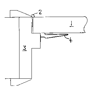
L'invention concerne un dispositif de protection appliqué à une porte. Ce dispositif comporte une gaine protectrice (4) contre le vide situé au niveau du côté charnière d'un ensemble porte (1) et encadrement de porte (3). La gaine de protection (4) est une bande de matière rigide, articulée autour de son axe secondaire, la bande étant dotée d'éléments de fixation situés au niveau de ses bords allongés grâce auxquels chaque bord peut être fixé individuellement à la porte (1) et à l'encadrement de la porte (3). La bande peut comporter une charnière orientée de manière longitudinale. Les éléments de fixation peuvent permettre un mouvement vertical d'une porte à charnières du type à goupille protubérante.


Abrégé anglais


A door safety device comprises a cover (4) for the gap at the hinge side of a
door (1) and
door frame (3) combination. The cover (4) is a strip of a rigid material which
is flexible
about its major axis, the strip having attachment means at its long edges
whereby each edge
may be secured respectively to the door (1) and door frame (3). The attachment
means being
arranged such that one edge is firmly fixed to one of the door/door frame
combination and the
other edge is fixed to the other member of the combination in a way that
allows some vertical
movement of that edge. The cover (4) is formed with rigid portions and
longitudinally-directed
fold areas such that part of the cover may be supported against a vertical
edge of the
door when the door is in an open condition.
This arrangement allows the safety device to be fitted to doors with either
the conventional
or the rising-butt type of hinge and it can prevent a child's hand from being
inserted into the
gap and thus being at risk of injury.

Revendications

Note : Les revendications sont présentées dans la langue officielle dans laquelle elles ont été soumises.


CLAIMS
The embodiments of the invention in which an exclusive property or privilege
is claimed
are defined as follows:
1. A door safety device comprising a cover for a gap at a hinge side of a door
and door
frame combination, the cover comprising a step of a rigid material which is
flexible about its
major axis, said strip having first and second long edges, the strip having
securing means at its
long edges such that the said first edge may ba secured to the door and the
said second edge to
the door frame of the combination, the securing means being such that one edge
is firmly fixed to
one of the door/door frame combination whilst the other edge is fixed in a
manner that allows a
vertical movement of that edge with respect to the other member of the
combination, and the
cover being formed with rigid portions and three longitudinally-directed
hinges, the arrangement
being such that 3 vertical edge of a door when present forms a support for one
rigid vertical
portion of the device whereby the device will be maintained in a generally
convex attitude whilst
the door is being opened and closed.
2. A device as claimed in Claim 1, in which the cover is formed of four rigid
portions
connected by three fold areas.
3. A device as claimed in Claim 1 or 3, in which the cover is formed of a
fibrous or fluted
board material.
4. A device as claimed in any one of Claims 1 to 3, in which one strip edge is
formed in a T-
shape, the said edge being positioned in a C-shaped housing for vertical
movement with respect
to the housing.
5. A device as claimed in any one of Claims 1 to 4, in which the cover is
shaped from a
plastics material with the fold areas being formed integrally in a plastics
moulding construction.
6. A method of making a door safety device as claimed in any one of claims 1
to 5, the
method comprising the step of moulding the said strip of rigid material in a
plastics extrusion
process with the hinge areas of the strip being formed of a soft plastic
material in a co-extrusion
process.

Description

Note : Les descriptions sont présentées dans la langue officielle dans laquelle elles ont été soumises.


CA 02288164 2005-02-15
-I-
DOOR SAFETY DEVICE
This invention relates to a door safety device. It relates particularly to a
device for fitting
at the hinge side of a door and door frame in order to reduce the risk of
injury to a child's fingers
if they should attempt to enter this space.
When a door is in the open position, the hinge side of the opening between the
door side
and the door frame offers a gap into which a young child's hand or fingers can
very easily be
inserted. If the door should then be closed, possibly by another child or by
pressure from a
draught of wind, there is a serious risk that the hand or fingers will become
hurt or badly
damaged. In time, of course, any child will learn that the gap at the edge of
a door that is being
closed is a dangerous area in the home and any fingers should be kept well
away from this zone.
However, the younger child will not be aware of this risk and may suffer a
crushed finger.
The present invention was devised to provide a shield that would reduce the
risk of injury
to a child's hand.
According to the invention, there is provided a door safety device comprising
a cover for
a gap at the hinge side of a door and door frame combination, the cover
comprising a strip of
rigid material which is flexible about its major axis, said strip having first
and second long edges,
the strip having attachment means at its long edges so that the fwst edge may
be secured to the
door and the said second edge to the door frame of the combination, the
securing means being
such at one edge is firmly fixed to one of the door/door frame combination
whilst the other edge
is fixed in a manner that allows a vertical movement of that edge with respect
to the other
member of the doorldoor frame combination, and the cover being formed with
rigid portions and
longitudinally-directed hinges, the arrangement being such that a vertical
edge of a door when
present forms a support for one rigid portion of the device whereby the device
will be maintained
in a generally convex attitude whilst the door is being opened and closed.

CA 02288164 1999-10-29
-2-
The cover may be formed of four rigid portions connected by three fold areas.
The cover
may be made of a fibrous or fluted board material.
The attachment means at one side of the strip may include the strip edge being
formed in a
T-shape and this edge being positioned in a C-shaped housing which will hold
the T-shape
yet allow the necessary vertical movement.
By way of example, some particular embodiments of the invention will now be
described
with reference to the accompanying drawings, in which:
Figure 1 is a partial horizontal cross-sectional view through a door and door
frame when
fitted with the door safety device,
Figure 2 is a view similar to that of Figure 1 when the door has been opened
through an
angle of sixty degrees,
Figure 3 is a similar view when the door has been opened fully,
Figure 4 is a cross-sectional view through the safety device,
Figures 5 and 6 are similar views of a different embodiment of safety device,
Figures 7 and 8 show a further embodiment, and,
Figure 9 depicts on a reduced scale a view of a door and door frame with a
fitted safety
device.
As shown particularly in Figure 1, the safety device is intended to be fitted
at the hinge
side of a door located in a door frame so that it will cover the large gap
that appears when the
door is opened. It is not necessary for the device to extend the full length
of the vertical door
side because a young child cannot be expected to reach very far up the door
side. Therefore,
a cover which extends a little more than halfway up the door side is likely in
practice to be
sufficient protection.
~ ,.: 'r.,.~ yF ~'~ ~ ' : .

CA 02288164 1999-10-29
-3-
Figures 1 to 3 show the door being opened to different angles with respect to
the door
frame. The door 1 is mounted on hinges 2 that are located on the door frame 3.
The safety
device 4 is adhesively secured at one side to the door 1 and at the other side
to the door frame
3. When the door is in the closed position (Figure 1), the safety device 4
forms a flattened
shape which occupies the corner where the door and frame come together. As the
door is
opened, the device 4 unfolds into a generally convex shape (Figures 2 and 3)
which will tend
to cover over the gap that appears with the greater angle of opening. A
child's fingers will
thus be prevented from entering this gap so there will be a reduced risk of
accidental damage
when the door closes. Upon closure of the door, the safety device 4 becomes
folded again so
that it will return to the position of Figure 1.
Figure 4 shows a cross-sectional view of the safety device which was made of a
PVC
composition with sections of rigid and flexible material. At the left hand
side, the view
depicts a T-shaped foot 6 which carries an adhesive pad 7. The foot 6 is
attached by means
of a fold area 8 to a rigid portion 9 and then by a further fold area 8 to a
second rigid portion
11. The second rigid portion 11 is attached by another fold area 8 to a plate
12 on which a
further adhesive pad 7 is located.
In operation of the safety device, the pads 7 are secured in the positions
shown in Figure 1
to the door and door frame. The installation is effected with the rigid
portions (9,11) being
bent about their connecting fold area 8. Upon opening the door 1, the rigid
portions (9,11)
then unfold from one another and open outwards so that a convex shield is
provided over the
door edge gap. When the door reaches the position depicted in Figure 3, the
second rigid
portion 11 is seen to lie in contact with the flat surface of the door 1 so
that the door edge 13
forms a fulcrum for supporting the rigid portion 11. The door edge 13 thus
serves to
~'''f;~:'°' :'° ° :. :;;_ ,. ..

CA 02288164 1999-10-29
-4-
maintain the convex shape of the safety device 4 so that it is unlikely to be
distorted by
pressure from a child's fingers.
Figures S and 6 show a further embodiment which is particularly suitable for
being made
from a board material such as a rigid cardboard, a fluted board or a board
made of a plastics
material. The different parts have the same reference numerals as those
already described. In
Figure 6, the fold areas 8 are made by a creasing operation on the board.
Whilst the embodiments already described are suitable for use on doors with
conventional
door hinges, there is also in common use a different hinge termed a rising-
butt hinge which
allows a small vertical movement of the door upon opening so that a raised
carpet edge can be
cleared. The embodiment shown in Figures 5 and 6 is readily adapted for this
type of hinge
since the board material of the device can be allowed vertical movement by
providing a
vertical column of diagonally directed slits along the length of the device.
There are also
other ways of obtaining the vertical movement capability such as combinations
of cutting and
creasing and these techniques will be well-known to those familiar with this
material.
In order to provide a safety device that was suited to both conventional and
rising-butt
door hinges, the embodiment shown in Figures 7 and 8 was devised. In this
construction,
the foot 6 is replaced by an anchor 14 in the shape of a letter T which is
capable of being
secured in a C-shaped housing 16. The housing 16 is provided with its own
adhesive pad 7
by which it may be attached to the door frame 3. The housing 16 thus forms a
secure fixing
for the anchor 14 but it permits the anchor to move up and down along the
housing as may be
required to compensate for the vertical movement of a door mounted on rising-
butt hinges.
Figure 9 shows a door 1 located in a door frame 3 with the safety device 4 of
the invention
mounted at the hinge side of the door 1. It will be seen that the device 4
does not need to

CA 02288164 1999-10-29
-S-
extend up the full height of the door because a young child will not be able
to reach much
more than halfway up the door. The safety device 4 is designed to fold
automatically upon
closure of the door so that it can remain unobtrusive in appearance.
The foregoing description of embodiments of the invention has been given by
way of
example only and a number of modifications may be made without departing from
the scope
of the invention as defined in the appended claims. For instance, instead of
the safety device
edges being secured by adhesive pads, an alternative method such as screw
fixings could be
used. The plastics material used for the safety device has been described as a
combination
of rigid and flexible PVC material. This is preferably a translucent PVC or
even a PVC that
has been given a light blue tint. It is also preferred that the safety device
will have an
unobtrusive appearance when it is located on the protected door and there are
likely to be
many other plastics and alternative materials that will fulfil this object.
....~ si=; : .:-~~=.~

Dessin représentatif
Une figure unique qui représente un dessin illustrant l'invention.
États administratifs

2024-08-01 : Dans le cadre de la transition vers les Brevets de nouvelle génération (BNG), la base de données sur les brevets canadiens (BDBC) contient désormais un Historique d'événement plus détaillé, qui reproduit le Journal des événements de notre nouvelle solution interne.

Veuillez noter que les événements débutant par « Inactive : » se réfèrent à des événements qui ne sont plus utilisés dans notre nouvelle solution interne.

Pour une meilleure compréhension de l'état de la demande ou brevet qui figure sur cette page, la rubrique Mise en garde , et les descriptions de Brevet , Historique d'événement , Taxes périodiques et Historique des paiements devraient être consultées.

Historique d'événement

Description Date
Inactive : Périmé (brevet - nouvelle loi) 2017-05-01
Inactive : TME en retard traitée 2015-07-30
Lettre envoyée 2015-05-01
Inactive : Lettre officielle 2011-08-11
Inactive : TME en retard traitée 2008-05-02
Lettre envoyée 2008-05-01
Accordé par délivrance 2007-01-23
Inactive : Page couverture publiée 2007-01-22
Préoctroi 2006-11-09
Inactive : Taxe finale reçue 2006-11-09
Un avis d'acceptation est envoyé 2006-05-11
Lettre envoyée 2006-05-11
month 2006-05-11
Un avis d'acceptation est envoyé 2006-05-11
Inactive : Approuvée aux fins d'acceptation (AFA) 2006-03-03
Modification reçue - modification volontaire 2005-12-22
Inactive : Dem. de l'examinateur par.30(2) Règles 2005-07-04
Modification reçue - modification volontaire 2005-02-15
Inactive : Dem. de l'examinateur par.30(2) Règles 2004-08-16
Inactive : Lettre officielle 2004-06-08
Exigences relatives à la révocation de la nomination d'un agent - jugée conforme 2004-06-08
Exigences relatives à la nomination d'un agent - jugée conforme 2004-06-08
Demande visant la nomination d'un agent 2004-04-28
Demande visant la révocation de la nomination d'un agent 2004-04-28
Modification reçue - modification volontaire 2002-11-29
Lettre envoyée 2002-06-19
Requête d'examen reçue 2002-04-29
Exigences pour une requête d'examen - jugée conforme 2002-04-29
Toutes les exigences pour l'examen - jugée conforme 2002-04-29
Inactive : Page couverture publiée 1999-12-21
Inactive : CIB attribuée 1999-12-15
Inactive : CIB en 1re position 1999-12-15
Inactive : Notice - Entrée phase nat. - Pas de RE 1999-12-01
Demande reçue - PCT 1999-11-29
Déclaration du statut de petite entité jugée conforme 1999-10-29
Demande publiée (accessible au public) 1998-11-12

Historique d'abandonnement

Il n'y a pas d'historique d'abandonnement

Taxes périodiques

Le dernier paiement a été reçu le 2006-04-28

Avis : Si le paiement en totalité n'a pas été reçu au plus tard à la date indiquée, une taxe supplémentaire peut être imposée, soit une des taxes suivantes :

  • taxe de rétablissement ;
  • taxe pour paiement en souffrance ; ou
  • taxe additionnelle pour le renversement d'une péremption réputée.

Les taxes sur les brevets sont ajustées au 1er janvier de chaque année. Les montants ci-dessus sont les montants actuels s'ils sont reçus au plus tard le 31 décembre de l'année en cours.
Veuillez vous référer à la page web des taxes sur les brevets de l'OPIC pour voir tous les montants actuels des taxes.

Historique des taxes

Type de taxes Anniversaire Échéance Date payée
TM (demande, 2e anniv.) - petite 02 1999-05-03 1999-10-29
Taxe nationale de base - petite 1999-10-29
TM (demande, 3e anniv.) - petite 03 2000-05-01 2000-04-28
TM (demande, 4e anniv.) - petite 04 2001-05-01 2001-04-30
Requête d'examen - petite 2002-04-29
TM (demande, 5e anniv.) - petite 05 2002-05-01 2002-04-29
TM (demande, 6e anniv.) - petite 06 2003-05-01 2003-05-01
TM (demande, 7e anniv.) - petite 07 2004-05-03 2004-04-28
TM (demande, 8e anniv.) - petite 08 2005-05-02 2005-04-29
TM (demande, 9e anniv.) - petite 09 2006-05-01 2006-04-28
Taxe finale - petite 2006-11-09
TM (brevet, 10e anniv.) - petite 2007-05-01 2007-05-01
TM (brevet, 11e anniv.) - générale 2008-05-01 2008-05-02
Annulation de la péremption réputée 2015-05-01 2008-05-02
TM (brevet, 12e anniv.) - petite 2009-05-01 2009-05-01
TM (brevet, 13e anniv.) - petite 2010-05-03 2010-05-03
TM (brevet, 14e anniv.) - petite 2011-05-02 2011-05-02
TM (brevet, 15e anniv.) - générale 2012-05-01 2012-04-11
TM (brevet, 16e anniv.) - petite 2013-05-01 2013-04-29
TM (brevet, 17e anniv.) - générale 2014-05-01 2014-04-28
Annulation de la péremption réputée 2015-05-01 2015-07-30
TM (brevet, 18e anniv.) - petite 2015-05-01 2015-07-30
TM (brevet, 19e anniv.) - petite 2016-05-02 2016-04-29
Titulaires au dossier

Les titulaires actuels et antérieures au dossier sont affichés en ordre alphabétique.

Titulaires actuels au dossier
STEPHEN ROBERT WEBB
Titulaires antérieures au dossier
S.O.
Les propriétaires antérieurs qui ne figurent pas dans la liste des « Propriétaires au dossier » apparaîtront dans d'autres documents au dossier.
Documents

Pour visionner les fichiers sélectionnés, entrer le code reCAPTCHA :


Pour visualiser une image, cliquer sur un lien dans la colonne description du document (Temporairement non-disponible). Pour télécharger l'image (les images), cliquer l'une ou plusieurs cases à cocher dans la première colonne et ensuite cliquer sur le bouton "Télécharger sélection en format PDF (archive Zip)" ou le bouton "Télécharger sélection (en un fichier PDF fusionné)".

Liste des documents de brevet publiés et non publiés sur la BDBC .

Si vous avez des difficultés à accéder au contenu, veuillez communiquer avec le Centre de services à la clientèle au 1-866-997-1936, ou envoyer un courriel au Centre de service à la clientèle de l'OPIC.

({010=Tous les documents, 020=Au moment du dépôt, 030=Au moment de la mise à la disponibilité du public, 040=À la délivrance, 050=Examen, 060=Correspondance reçue, 070=Divers, 080=Correspondance envoyée, 090=Paiement})


Description du
Document 
Date
(aaaa-mm-jj) 
Nombre de pages   Taille de l'image (Ko) 
Dessin représentatif 1999-12-20 1 3
Abrégé 1999-10-28 1 26
Description 1999-10-28 5 195
Revendications 1999-10-28 2 48
Dessins 1999-10-28 2 27
Description 2005-02-14 5 200
Revendications 2005-02-14 1 50
Revendications 2005-12-21 1 38
Abrégé 2006-11-20 1 26
Dessin représentatif 2006-11-27 1 3
Avis d'entree dans la phase nationale 1999-11-30 1 193
Rappel - requête d'examen 2002-01-02 1 117
Accusé de réception de la requête d'examen 2002-06-18 1 193
Avis du commissaire - Demande jugée acceptable 2006-05-10 1 162
Avis concernant la taxe de maintien 2008-05-15 1 172
Quittance d'un paiement en retard 2008-05-15 1 165
Avis concernant la taxe de maintien 2015-06-11 1 171
Quittance d'un paiement en retard 2015-07-29 1 164
Taxes 2013-04-28 1 155
PCT 1999-10-28 28 740
Taxes 2003-04-30 1 30
Taxes 2002-04-28 1 30
Taxes 2001-04-29 1 29
Taxes 2000-04-27 1 30
Correspondance 2004-04-27 1 34
Taxes 2004-04-27 1 34
Correspondance 2004-06-07 1 17
Correspondance 2004-06-07 1 14
Taxes 2005-04-28 1 31
Taxes 2006-04-27 1 34
Correspondance 2006-11-08 1 29
Taxes 2007-04-30 1 31
Taxes 2008-05-01 1 30
Taxes 2009-04-30 1 28
Taxes 2010-05-02 1 30
Taxes 2011-05-01 1 28