Note : Les descriptions sont présentées dans la langue officielle dans laquelle elles ont été soumises.
CA 02288324 1999-11-02
TRUCK HOIST
FIELD OF THE INVENTION
This invention relates to new and improved hoists
useful for raising or lowering the dump bed of a truck.
More particularly, this invention relates to underbody
hoists which provide substantially improved lifting
efficiency of the hydraulic cylinder and optionally provide
a mechanism for locking the cylinder in place to provide
greater stability when the dump bed is elevated during the
dumping operation.
BACKGROUND OF THE INVENTION
Many types of hydraulic hoists have been developed
over the years which are particularly useful as underbody
hoists for raising and lowering a dump bed, such as the
dump bed of a heavy duty dump truck or trailer. Generally
speaking, these hoists employ hydraulic cylinders which,
when activated, pivot the dump bed about its rear pivots
connected to the~frame of the truck chassis.
1
CA 02288324 1999-11-02
In a typical hydraulic truck hoist, a hydraulic
cylinder lies lengthwise between the framerails of the
vehicle and underneath the truck bed. As the hoist's
cylinder extends, one end pushes against the underside of
the dump bed while the other end of the cylinder, being
pivotally attached to the frame members (usually cross
members) of the vehicle, pivots to allow the dump bed to
raise. At the beginning of the lifting process, the
cylinder is nearly parallel to the dump bed and thus has
very little initial leverage. Most of the force of the
cylinder at this point in the lift process is directed
towards the rear hinge that connects the dump bed to the
truck frame. Due to this inefficiency, large cylinders are
required to provide the substantial forces necessary to
achieve this initial lift.
Many types of hydraulic hoists have been developed to
address this initial lift problem. In one example,
telescopic cylinders are mounted farther forward on the
truck frame. This provides the cylinder with greater
initial leverage. However, the cylinder in such devices
usually must have a rather long stroke to achieve a
sufficient dump angle.
2
CA 02288324 1999-11-02
Other attempts to improve these hoists have included
the use of a simple lever arm to provide the lifting motion
in an attempt to obtain a more efficient lift angle.
Examples include those hoists disclosed in U.S. Patent No.
4,052,105. Other designs include those disclosed in U.S.
Patent Nos. 2,509,911; 2,603,518; and 4,762,370. These
patents disclose hoist designs where a lever provides the
initial lift of the truck bed, and a cylinder completes the
lifting process.
Generally speaking, truck hoist designs known prior to
the subject invention have one or more drawbacks associated
with their use. For the most part, they often require
large and expensive cylinders. Many are difficult to
install or manufacture. Other designs are subject to large
stresses, are potentially unstable when elevated, or do not
achieve superior initial lift. Stability problems have
been known to occur, for example, when wet loads are
carried and the entire load is riot eliminated during the
dumping operation, leaving, for example, some of the load
in the most elevated part of the dump bed.
In view of the above, it is apparent that there exists
a need in the art for a hoist which can efficiently raise
3
CA 02288324 1999-11-02
and lower a truck bed and which is not subject to the above
drawbacks. It is a purpose of this invention to fulfill
this need in the art, as well as other needs which will
become apparent to the skilled artisan once given the
following disclosure.
SUMMARY OF INVENTION
Generally speaking, this invention fulfills the above-
described needs in the art by providing a hoist for raising
or lowering a truck bed to and from a truck frame which is
capable of being located between the bed and the frame, the
hoist comprising: an extendible and retractable cylinder
connected at one end to a lever mechanism and at the other
end connectable to the underside of a bed, the lever
mechanism comprising at least a first pivot, a first pivot
centerline, a second pivot, and an elongated arm, the first
pivot being attachable to a truck frame and the second
pivot being rotatably attached to the cylinder, the second
pivot being located at a first offset distance from the
centerline of the first pivot, and being rotatable about
the first pivot when the cylinder is extended or retracted,
4
CA 02288324 1999-11-02
the elongated arm being pivotally connected to the first
pivot at one end and comprising a first roller mechanism
for engagement with a truck bed at the other end, the
elongated arm extending and angling upwardly from the first
pivot; the lever mechanism being so located that when the
cylinder is caused to extend, the cylinder pushes against
the lever mechanism causing the lever mechanism to rotate
about the first pivot, and causing the elongated arm to
raise the bed from the frame; the hoist further including
a stop mechanism so located at a selected offset distance
from the first pivot centerline opposite the side of the
first pivot centerline of the first offset distance, such
that when the second pivot is caused to rotate into contact
with the stop mechanism, further extension of the cylinder
causes the cylinder to raise the bed further from the
f rame .
In certain further embodiments of this invention, a
hoist for raising or lowering a truck bed to and from a
truck frame capable of being located between the bed and
the frame comprises: an extendible and retractable
cylinder connected at one end to a lever mechanism and at
the other end connectable to the underside of the bed, the
S
CA 02288324 1999-11-02
lever mechanism comprising at least a first pivot, a second
pivot, and an elongated arm, the first pivot being
attachable to the truck frame and the second pivot being
rotatably attached to the cylinder, the second pivot being
located at a first offset distance from the centerline of
the first pivot, and being rotatable about the first pivot
when the cylinder is extended or retracted, the elongated
arm being pivotally connected to the first pivot at one end
and designed for engagement with the truck bed at the other
end, the elongated arm extending from the first pivot; the
lever mechanism being so located that when the cylinder is
caused to extend, the cylinder pushes against the lever
mechanism causing the lever mechanism to rotate about the
first pivot, and causing the elongated arm to raise the
bed from the frame; the hoist further including a stop
mechanism such that when the lever mechanism is caused to
stop by the stop mechanism, further extension of the
cylinder causes the cylinder to raise the bed further from
the frame; the hoist further comprising a locking device to
lock the second pivot at its point of rotation about the
first pivot.
6
CA 02288324 1999-11-02
In certain other embodiments, the locking device
comprises at least one locking mechanism pivotally
connected to the hoist, at least one linkage mechanism
pivotally attached to the lever mechanism on the first
S pivot and pivotally attached to the locking mechanism, a
second roller mechanism pivotally attached to the linkage,
whereby, when the cylinder raises the bed, the second
roller mechanism rolls against the cylinder causing the
linkage mechanism to position the locking mechanism against
the force of a biasing mechanism, such that the second
pivot locks at its position of rotation about the first
pivot.
In still further embodiments, a track mechanism is
provided which is connectable to the underside of the truck
bed for engagement with the elongated arm. This track may
extend either parallel to or at angle to the truck bed.
This invention will now be described with respect to
certain embodiments thereof as set forth in the
accompanying illustrations, wherein:
7
CA 02288324 1999-11-02
IN THE DRAWINGS
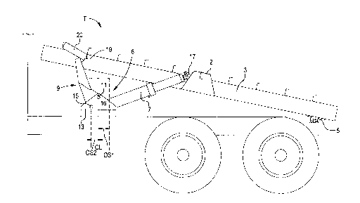
FIG. 1 is a partial side view of a truck having a
raisable and lowerable dump bed, embodying a hoist
according to the subject invention.
FIG. 2 is a side plan view of the embodiment of FIG.1
illustrating the hoist near the end of the first lift
phase.
FIG. 3 is a partial side view of the embodiment of
FIG.1 showing the hoist during the second lift phase.
FIG. 4 is a partial, 3-dimensional view of the lever
mechanism, top plate removed, according to the subject
invention.
FIG. 5 is a partial 3-dimensional view of the
embodiment of FIG.1 with certain parts shown in X-ray.
FIG. 6 is a partial side view of the embodiment of
FIG. 1 further including a locking device according to the
subject invention.
FIG. 7 is a partial rearward 3-dimensional view of the
embodiment of FIG. 4 illustrating the locking device i n
its "locked" position.
8
CA 02288324 1999-11-02
FIG. 8 is a diagrammatic representation of a partial
side sectional view of the embodiment of FIG. 3
illustrating the operation of the locking device.
DETAILED DESCRIPTION OF CERTAIN
EMBODIMENTS
With initial reference to FIG. 1, there is illustrated
a partial view of a conventional dump truck T with various
conventional parts not shown so as to better illustrate
novel hoist 6. Generally speaking, however, dump truck T's
relevant parts as they relate to this embodiment of the
invention include a pair of longitudinal truck frame rails
1 on either side of the vehicle, frame 3 of a typical dump
bed (the actual bed being omitted for clarity), and a rear
pivot 5, all conventional in the art. Further illustrated
in FIGS. 2, 3, 4, and 5 are the various elements of a hoist
6, as one exemplar embodiment according to this invention.
As illustrated, hoist 6 is attached between truck frame
rails 1 and frame 3 of the dump bed by mounting bracket 13.
Hoist 6 is further pivotally attached at pivot 17 to dump
bed frame mounting bracket 2. Dump bed frame mounting
9
CA 02288324 1999-11-02
bracket 2 is fixedly connected to the underside of dump bed
frame 3 and contains pivot 17. Hoist 6 is comprised of an
extendible and retractable cylinder 7 and a lever mechanism
generally indicated at 9. Optionally, a track 20 is
attached parallel or at an angle to dump bed frame 3.
Referring particularly to FIGS. 4, 5, and 7, lever
mechanism 9 includes roller 19, pivot 11, pivot 15, and an
extended arm comprised of two parallel side plates 10 and
12 and optionally, a top plate structure made up of plates
14 (not shown in FIG. 4 for clarity). Roller 19 is
designed for engagement with track 20 which is located on
cross members 90 and 91 intermediate frame rails 3 of the
dump bed. Roller 19 can be of several types including an
actual roller or one which merely slides on track 20.
Pivot 11 connects lever mechanism 9 to mounting
bracket 13 and has a centerline CL whose importance to this
invention will be disclosed more fully below. Pivot 15 on
lever mechanism 9 serves as it's pivotal connection to
cylinder 7. More specifically, cylinder 7 is pivotally
attached at its base to pivot 15 between parallel side
plates 10 and 12. At its opposite end, cylinder 7 is
pivotally connected to dump bed frame mounting bracket 2 at
CA 02288324 1999-11-02
pivot 17. When hoist 6 is in the lowered position as in
FIG. 1, pivot 15 is located at a first selected offset
distance OS1 from centerline CL of pivot 11, towards the
rear pivot 5 of the vehicle. Top plate structure 14
S comprises a plurality of flanges (plate members) extending
perpendicular from side plates 10 and 12. Top plate
structure 14 joins side plates 10 and 12 along the length
of lever mechanism 9 from pivot 11 to roller 19, leaving
lever mechanism 9 substantially open at pivot 15 for
connection to cylinder 7. Referring to FIGS. 3 and 4, the
embodiment of lever mechanism 9, as illustrated, further
includes three segments 21, 23, and 25. These segments
form an obtuse angle at the junction of segments 21 and 23
and at the junction of segments 23 and 25. Segment 23
angles upwardly and rearwardly as it extends from its
junction with segment 21, and segment 25 angles further
upwardly and rearwardly as it extends from its junction
with segment 23.
It is understood, of course, that it is the relative
location of roller 19 and pivots 11 and 15 which
principally enables the efficiency of the subject
invention. Lever mechanism 9, as is apparent to the
11
CA 02288324 1999-11-02
skilled artisan, may be of a different construction while
still incorporating the important relative locations of
these pivots etc.
Referring now to FIG. 5, pivot 11 comprises a cross-
shaft assembly which substantially spans the width between
frame rails 1 and pivotally attaches lever mechanism 9 to
mounting bracket 13. Mounting bracket 13 is fixedly
attached to truck frame rails 1. Mounting bracket 13
comprises two opposing parallel side plates 16 and 18, each
fixedly mounted on a truck frame rail 1. Mounr_;na hra~kAr
13 further includes stop mechanism 27. Stop mechanism 27
comprises two longitudinal cross-members spanning truck
frame rails 1 between opposing parallel side plates 16 and
18 and is fixedly connected to each plate. Alternatively,
stop mechanism 27 may comprise a single cross-member or may
be connected to truck frame rails 1, or may be connected to
both truck frame rails 1 and side plates 16 and 18. Stop
mechanism 27 is further located at a selected second offset
distance OS2 from centerline CL of pivot 11 on the side
opposite that of OS1.
The hoist, of course, can include more than one
cylinder or lever mechanism. Cylinders may be used that
12
CA 02288324 1999-11-02
are either single stage or multi-stage telescopic, with
multi-stage being preferred, because the forward mounting
causes less stress and strain on the entire assembly. If
single stage cylinders are used, the hoist assembly should
normally be mounted towards the rear of the truck frame 1.
The unique operation of hoist 6 will now be described.
As will be seen, hoist 6 lifts in two distinct lift phases,
wherein during the critical first phase there is a two
point lift, but while in the second phase, only one point
of lift is employed, thereby achieving the unique efficient
results of this invention.
As shown in FIG. 1, the hoist is in its lowered
position before the lifting process begins. The extendible
and retractable cylinder 7 lies substantially horizontal
and lengthwise between truck frame rails 1 and underneath
truck bed frame 3. Pivot 15 is located at its first
selected offset distance OS1 from the centerline CL of
pivot 11, on the side of centerline CL towards rear pivot
5. As cylinder 7 is pressurized with hydraulic oil by
conventional pump and power take off apparatus (not shown),
cylinder 7 begins to extend and push against its connection
13
CA 02288324 1999-11-02
to lever mechanism 9 at pivot 15 to initiate the first lift
phase. This causes lever mechanism 9 to rotate about pivot
11 in a clockwise direction. This rotation causes lever
mechanism 9, at its roller 19, to engage with track 20 on
the underside of truck bed frame 3.
As hydraulic pressure in cylinder 7 increases and
cylinder 7 continues to extend, further rotation of lever
mechanism 9 about pivot 11 causes roller 19 to push
upwardly on track 20 and cylinder 7 to push upwardly at
pivot 17. This causes truck hP~ frame Z ~~ ,~~~ L__
pivoting, about pivot 5 to a height illustrated in FIG. 2.
When the leading edge of lever mechanism 9 contacts stop
mechanism 27, further rotation of lever mechanism 9 is
prevented, thus completing the first lift phase.
As can be seen, at the end of this first lift phase,
pivot 15 has rotated about pivot 11 from its starting
position at the first selected offset distance OS1,
clockwise and substantially past the centerline CL of pivot
11 to a second selected offset distance OS2. This second
selected offset distance OS2 is opposite the side of the
centerline CL of the first selected offset distance OS1.
This extra rotation of pivot 15 about pivot 11 past the
14
CA 02288324 1999-11-02
centerline CL to second selected offset distance OS2, as
applied to the upward angular construction of lever
mechanism 9, results in a superior initial lift height of
truck bed frame 3 over the prior art and positions cylinder
7 at a substantially more efficient lift angle to bed frame
3. Additionally, as stated above, during this first lift
phase, the hoist of the subject invention employs two
distinct points of lift, ie. at roller 19 and at pivot 17.
In certain designs, roller 19 may be designed to provide
2/3 of the initial lift force, while cylinder 7 at pivot 17
will then provide the remaining 1/3. In combination, this
allows the second lift phase (described below) to now be
completed with substantially less required force as
compared to hoists known in the art. This design further
utilizes up to a third less hydraulic oil, allowing the use
of smaller and less expensive cylinders.
Referring now to FIG. 3, and to describe the second
lift phase, lever mechanism 9 has, at the end of the first
lift phase, contacted stop mechanism 27 which prevents
further rotation of pivot 15 about pivot 11. As cylinder
7 is further pressurized, cylinder 7 continues to extend
and pushes against pivot 17 of dump bed frame mounting
CA 02288324 1999-11-02
bracket 2 located on the underside of dump bed frame 3.
This additional extension of cylinder 7 further raises dump
bed frame 3 about pivot 5 and causes roller 19 of lever
mechanism 9 to disengage with track 20 because stop
mechanism 27 prevents further rotation of lever mechanism
9. Dump bed frame 3 continues to be raised solely at pivot
17 until it is in a fully raised position. This completes
the second lift phase.
Referring initially to FIG. 6, there is illustrated
a conventional dump truck T, which further includes a
second embodiment of hoist 6 according to the subject
invention, that incorporates a locking device for
improved safety and stability in the dump bed raising and
lowering process. Conventional dump truck T is
illustrated with various conventional parts not shown so
as to better illustrate novel hoist 6 and the
incorporated locking device.
The locking device, generally indicated at 29,
locks lever mechanism 9 and one end of extendible and
retractable cylinder 7 in place during certain phases of
the lifting and lowering cycle. More specifically, the
locking device 29 functions by locking pivot 15 at its
1G
CA 02288324 1999-11-02
position of rotation about pivot 11 against stop
mechanism 27. Locking pivot 15 against stop mechanism 27
immobilizes lever mechanism 9, preventing further
rotation of lever mechanism 9 about pivot 11, clockwise
or counter-clockwise, and further locks the base of
cylinder 7 in place during these particular critical
phases of the lifting and lowering cycle. This provides
safety and stability to the hoist especially when lifting
wet or unstable loads or when operating the hoist when
the truck is on uneven or unstable ground. This feature
would be particularly effective if a sudden load shift,
wet load, or other such factor caused dump bed frame 3 to
lift near or past vertical. The locking device 29 would
help prevent severe damage to the hoist or the truck, and
substantially lessen the chances of injury by preventing
unwanted rotation of lever 9 about pivot 11.
Referring now to FIGS. 6 and 7, locking device 29
comprises two hooks 31a and 31b, two torsion springs 33a
and 33b, a pivot rod 47, and a linkage mechanism,
generally indicated at 35. Hooks 31a and 31b are
pivotally attached to hook mounting brackets 34a and 34b
at pivots 32a and 32b located above stop mechanism 27.
17
CA 02288324 1999-11-02
Hook mounting brackets 34a and 34b are fixedly attached
to the top of stop mechanism 27, each on one side of
lever mechanism 9. Torsion springs 33a and 33b are
located about pivots 32a and 32b respectively, so that
S they bias hooks 31a and 31b upwards and in a
counterclockwise direction about pivots 32a and 32b.
Linkage mechanism 35 is pivotally attached to hoist 6 at
pivot 11, and is pivotally attached to hooks 31a and 31b
at pivots 43a and 43b. Pivot rod 47 substantially spans
the width of lever mechanism 9 and connects links 41a to
41b. Pivot rod 47 further includes roller 37 located at
its midpoint.
Linkage mechanism 35 comprises two sets of links,
39a and 39b and links 41a and 41b, each pair located
parallel and opposite the other set, one pair on each
side of lever mechanism 9. Links 39a and 39b are
pivotally attached to hooks 31a and 31b respectively at
pivots 43a and 43b respectively. Links 39a and 39b are
additionally pivotally attached to links 41a and 41b
respectively at pivots 45a and 45b respectively. Near
their midpoint, links 41a and 41b are pivotally attached
to pivot 11. Pivot 11 comprises a cross-shaft assembly
18
CA 02288324 1999-11-02
which substantially spans the width between frame rails 1
and attaches lever mechanism 9 to mounting bracket 13.
Mounting bracket 13 is fixedly attached to truck frame
rails 1.
The locking device operates as follows:
During operation of the hoist, at the end of the
first lift phase, lever mechanism 9 contacts stop
mechanism 27, preventing further rotation of pivot 15
about pivot 11. Although rotation of lever mechanism 9
about pivot 11 has stopped, cylinder 7 continues to
extend, pushing against pivot 17. This extension further
raises dump bed frame 3 about pivot 5. During this
second lift phase, as dump bed frame 3 raises, cylinder
7 is caused to angle upward about pivot 15 and engage
with roller 37 of pivot 47. This engagement causes
cylinder 7 to bias roller 37 in an upward direction,
causing pivot rod 47, which contains roller 37, to rotate
links 41a and 41b counterclockwise about pivot 11. This
rotation pushes links 39a and 39b at pivots 45a and 45b
in a downward direction. The downward movement of links
39a and 39b pushes hooks 31a and 31b, at pivots 43a and
43b, against the.biasing force of torsion springs 33a and
19
CA 02288324 1999-11-02
33b. As hooks 31a and 31b are pushed against the biasing
force of torsion springs 33a and 33b, the hooks rotate
about pivots 32a and 32b in a clockwise direction and are
positioned over pivot 15. The resulting placement of
hooks 31a and 31b, so that they encompass pivot 15, locks
pivot 15 at its point of rotation about pivot 11 and
against stop mechanism 27. Locking pivot 15 against stop
mechanism 27 immobilizes lever mechanism 9, preventing
unwanted rotation of lever mechanism 9 about pivot 11,
and further locks the base of cylinder 7 in place during
these particular critical phases of the lifting and
lowering cycle.
Reference is now made to FIG. 8 in which the
operation of the locking device 29 and the upward angular
movement of cylinder 7 about pivot 15 is demonstrated.
The movement of the relevant parts is illustrated by
arrows where the solid lines in the drawing represent the
initial position of cylinder 7 and the locking device 29
near the end of the first lift phase. The dotted lines
in the drawing represent the position of cylinder 7 and
locking device 29 at the point where hooks 31a and 31b
have fully immobilized pivot 15, after cylinder 7 and
CA 02288324 1999-11-02
locking device 29 have moved as illustrated by the
arrows.
This disclosure of the locking device relates
entirely to a single cylinder truck hoist. If a twin
cylinder hoist were used, each with its own lever
mechanism 9, there would be two rollers 37, with one
linkage mechanism 35, and one hook 31 located between the
two cylinders. Each cylinder would, of course, have its
own properly spaced pivot 17.
Once given the above disclosure, many other
features, modifications, and improvements will become
apparent to the skilled artisan. Such other features,
modifications, and improvements are therefore considered
to be part of this invention, the scope of which is to be
determined by the following claims:
21