Note : Les descriptions sont présentées dans la langue officielle dans laquelle elles ont été soumises.
CA 02288544 1999-11-04
Title: METHOD AND APPARATUS FOR ENHANCING THE
DISSOLUTION OF ONE FLUID IN ANOTHER FLUID
FIELD OF THE INVENTION
This invention relates of a method for dissolving a gas
into a liquid. The device may also be used to mix together two or
more gasses or two or more liquids. The gas may be present either by
itself or in combination with one or more other gasses and/or a
liquid. Further, the liquid into which the gas is to be dissolved may
be present by itself or may also have one or more liquids and/or one
or more other gases associated therewith.
BACKGROUND OF THE INVENTION
In many applications, it is desirable to dissolve a gas
into a liquid. Various different apparatus have been developed in
the past for dissolving gases into liquids. Examples of such
techniques include the use of a sparger, venturi or other inlet
devices for introducing gas bubbles into a liquid which is held in a
reactor. Another technique comprises passing a gas and a liquid in
counter current flow through a packed tower. It has also been
known to pass a liquid and a gas through a pump so as to intimately
mix the liquid and the gas to obtain a gas liquid mixture.
One disadvantage of these techniques is that only a
limited amount of the gas is dissolved or exposed to the liquid.
Further, if a pump is used, only limited pressures may be exerted on
the liquid/gas mixture in order to prevent cavitation. In order to
obtain higher dissolution efficiencies, the process must be repeated.
This may be achieved by recovering the undissolved gas and
recycling it through the process.
BRIEF SUMMARY OF THE INVENTION
In accordance with the instant invention, there is
provided a mixing apparatus comprising a housing; at least one
CA 02288544 1999-11-04
-2-
inlet port for introducing at least one gas and at least one liquid to
the housing; a plurality of spaced apart members rotatably mounted
within the housing; and, a drive member for rotating the spaced
apart members at a rate sufficient for dissolving at least a portion of
the gas into the liquid to form a liquid/gas mixture and at a rate
sufficient to maintain a laminar flow in a boundary layer adjacent
the spaced apart members.
One advantage of the instant invention is that, by the
use of a prandtl layer pump, the liquid and gas may be subjected to
high pressures (eg up to 250 psig) in a very compact space without
risk of cavitation. With conventional pumps, it would be necessary
to maintain a very large head pressure to prevent cavitation of the
gas as it passes through the pump. With the use of a prandtl layer
pump, it is possible to subject a gas to elevated pressures in the
pump without the need of a matching head pressure. thus the
pump may be used as a mixing apparatus at generally any location
in a process.
Another advantage of the instant invention is that at
the elevated pressures which may be achieved by using the method
and apparatus of the instant invention, increased dissolution of the
gas into the liquid may be achieved.
In one embodiment, the mixing apparatus also has as a
pressure reduction zone downstream from the spaced apart
members. The pressure to which the gas/liquid mixture is subjected
is preferably rapidly reduced when the gas/liquid mixture enters the
pressure reduction zone. The rapid pressure reduction allows at
least some of the dissolved gas to come out of solution to form a
fine dispersion of bubbles. Surprisingly, this rapid pressure
reduction results in the gas forming a suspension of bubbles which
may be ultra-fine (e.g. 1-5p). These bubbles define an extended
contact surface. For example, a bubble produced by a sparger
CA 02288544 1999-11-04
-3-
generally has a diameter of about 100 microns and has a surface area
of about 3.1 x 10-$ m2. A bubble when produced by this invention
may have a surface area of 7.9 x 10⁻¹¹ which is 2000 times greater.
The mixing apparatus may have a catalyst incorporated
therein or introduced therein. Preferably, the catalyst is used in
conjunction with the pressure reduction zone to take advantage of
the extended contact surface which is created by the bubbles. A
catalyst reactive with at least one of the gas and the liquid may be
applied to at least a portion of one of the spaced apart members.
Alternately, or in addition, a catalyst reactive with at least one of the
gas and the liquid may be provided in the pressure reduction zone.
The catalyst may be contained in the apparatus as a replaceable
member or it may be introduced into the apparatus as part of the
fluid stream, as a gas or a liquid or a solid but preferably in a liquid
or a solid form.
In one particulary preferred embodiment, the at least
one gas comprises ozone and the at least one liquid comprises water
and the mixing apparatus is used in the treatment of water. This
process takes advantage of the intimate contact which may be
obtained by the method and apparatus of the instant invention to
achieve a high level of disinfection in a relatively short period of
time. Further, by using the pressure reduction zone, a high degree of
reliability of the treatment is achieved due to the even distribution
of ozone in the water which occurs when the bubbles are formed
since the ozone is evolved from all portions of the water at the
reduced pressure conditions.
In another embodiment, at least two gases are
introduced through the inlet port and the at least one liquid is inert
whereby the at least one liquid is a media for the dissolution of one
of the gases into another of the gases or for the reaction of the gases
with each other.
CA 02288544 1999-11-04
-4-
In another embodiment, the inlet port comprises at
least two venturi, at least one gas being introduced through one of
the venturi and the liquid being introduced through the other
venturi.
In another embodiment, the inlet port includes a
member for dividing the gas into bubbles in the fluid.
In accordance with the instant invention, there is also
provided a mixing apparatus comprising means for creating a
boundary layer adjacent a plurality of spaced apart members
rotatably mounted within a housing; means for introducing at least
one gas and at least one liquid to the housing; a plurality of spaced
apart members rotatably mounted within the housing; and, means
for rotating the spaced apart members at a rate sufficient for
dissolving at least a portion of the gas into the liquid to form a
liquid/gas mixture.
In one embodiment, the mixing apparatus further
comprises means for rapidly depressurizing the gas/liquid mixture.
The mixing apparatus may also comprise means for contacting the
gas/liquid mixture with a catalyst reactive with at least one of the
gas and the liquid when the pressure to which the gas/liquid
mixture is subjected has been reduced.
In another embodiment, a catalyst reactive with at least
one of the gas and the liquid is applied to at least a portion of one of
the spaced apart members.
In another embodiment, the at least one gas comprises
ozone and the at least one liquid comprises water and the mixing
apparatus is used in the treatment of water.
In another embodiment, at least two gases are
introduced into the housing and the at least one liquid is inert
whereby the at least one liquid is a media for the dissolution of one
CA 02288544 1999-11-04
-5-
of the gases into another of the gases or for the reaction of the gases
with each other.
In another embodiment, a catalyst is introduced into
the mixing apparatus. The catalyst may be in a liquid or a solid form.
In another embodiment, the means for introducing at
least one gas and at least one liquid to the housing comprises means
for dividing the gas into bubbles in the fluid.
In accordance with the instant invention, there is also
provided a method for mixing a liquid and a gas comprising
introducing at least one gas and at least one liquid into a prandtl
layer pump and passing the gas and the liquid through the prandtl
layer pump to obtain a liquid/gas mixture.
In one embodiment, the method further comprises
passing the liquid/gas mixture through a pressure reduction zone to
obtain a liquid/gas mixture at a reduced pressure. Preferably, the
pressure to which the gas/liquid mixture is subjected is preferably
rapidly reduced.
In another embodiment, the method further comprises
exposing at least one of the liquid and the gas to a catalyst in the
housing.
In another embodiment, the method further comprises
exposing at least one of the liquid and the gas to a catalyst in the
pressure reduction zone.
In another embodiment, the at least one gas comprises
ozone and the at least one liquid comprises water and the method
comprises a process for the treatment of water.
In another embodiment, at least two gases are
introduced through the inlet port and the method comprises a
process for the dissolution of one of the gases into another of the
gases or for the reaction of the gases with each other.
CA 02288544 1999-11-04
-6-
In another embodiment, the method further comprises
introducing a catalyst into the mixing apparatus together with the at
least one gas and the at least one liquid.
In another embodiment, the method further comprises
separately introducing one of the at least one gas and the liquid into
the housing.
In another embodiment, the method further comprises
mixing the gas and the liquid to create gas bubbles in the liquid prior
to introducing the liquid and the gas into the prandtl layer pump.
In accordance with the instant invention, there is also
provided a method for mixing a liquid and a gas comprising the step
of subjecting at least one gas and at least one liquid to an elevated
pressure created at least in part by a plurality of rotating spaced apart
members to obtain a liquid/gas mixture.
In one embodiment, the method further comprises the
step of treating the liquid/gas mixture to obtain a solution
containing microbubbles.
In another embodiment, the method further comprises
the step of rapidly depressurizing the liquid/gas mixture.
In another embodiment, the method further comprises
the step of reacting at least one of the liquid and the gas with a
catalyst.
In another embodiment, the method further comprises
the step of treating the solution with a catalyst.
In another embodiment, the at least one gas comprises
ozone and the at least one liquid comprises water and the method
comprises a process for the treatment of water.
In another embodiment, at least two gases are subjected
to the elevated pressure conditions and the method comprises a
process for the dissolution of one of the gases into another of the
gases or for the reaction of the gases with each other.
CA 02288544 1999-11-04
_7_
In another embodiment, the method further comprises
the step of introducing the catalyst into the rotating spaced apart
members.
In another embodiment, the method further comprises
the step of separately introducing one of the at least one gas and the
liquid into the rotating spaced apart members.
In another embodiment, the method further comprises
the step of introducing a mixture of gas bubbles in the liquid to the
rotating spaced apart members.
BRIEF DESCRIPTION OF THE DRAWINGS
These and other advantages of the instant invention
may be more fully and particularly understood in connection with
the following description of a preferred embodiment of the
invention in which:
Figure 1 a schematic diagram of an apparatus according
to the instant invention; and,
Figure 2 is an alternate embodiment of a schematic
diagram of the apparatus of Figure 1.
DETAILED DESCRIPTION OF THE PREFERRED EMBODIMENT
The method and apparatus of the instant invention
comprises the use of a prandtl layer turbine as a device for mixing
fluids (eg. at least one gas with at least one other gas, at least one
liquid with at least one other liquid, and preferably at least one gas
with at least one liquid). Various embodiments of prandtl layer
turbines have been developed over the years. Prandtl layer turbines
comprise a plurality of rotatably mounted members (generally in
the form of flat discs which are typically relatively thin) which are
rotatably mounted in a housing. These devices are described in the
United States Patent No. 1,061,206 (Tesla).
CA 02288544 1999-11-04
Various designs of such apparatus have been developed
over the years but have generally not been employed commercially.
The design described in Tesla may be used as a pump or as a motor.
Such devices take advantage of the properties of a fluid when in
contact with the rotating surface of the discs. If the discs are driven
by the fluid, then as the fluid passes through the housing between
the spaced discs, the movement of the fluid will cause the discs to
rotate thereby generating power which may be transmitted via a
shaft for use elsewhere. Accordingly, such devices function as a
motor. Conversely, if the fluid in the housing is initially static, the
rotation of the discs will cause the fluid in the housing to
commence rotating in the same direction as the discs thereby
causing the apparatus to function as a pump, drawing the fluid
through the housing. In this application, all such devices are
referred to herein as a "prandtl layer turbine".
Various designs for prandtl layer turbines have been
developed. These include those disclosed in the United States
Patent No. 4,402,647 (Effenberger), United States Patent No. 4,218,177
(Robel), United States Re-Issue Patent No. 28,742 {Rafferty et al.),
United States Patent No. 5,470,197 (Cafarelli) and United States
Patent No. 4,655,679 {Giacomel). The method and apparatus of the
instant invention is applicable to all designs of a prandtl layer
turbine.
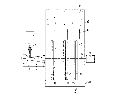
In the preferred embodiment shown in Figure 1, fluid 4
and gas 6 are introduced into a housing 30, for example, by being
drawn through a venturi 3 by means of a prandtl layer turbine 17.
The prandtl layer turbine 17 consists of a series of plates (preferably
discs) 5 which are non-rotatably mounted to a shaft 8 which is itself
rotatably mounted in housing 30 such as by being connected to a
motor 9 which provides the motive force to rotate the plates 5. The
rotation of the plates 5 causes the fluid 4 to be drawn through the
CA 02288544 1999-11-04
-9-
venturi 3 which in turn causes a gas 6 to be drawn from the gas
source 1 through tube 2 and into the venturi 3.
As shown in Figure 1, a single fluid stream is combined
with the single gas stream which are fed via venturi 3 into prandtl
layer turbine 17. It will be appreciated that gas 6 may comprise one
or more gases (which may be combined with one or more liquids)
and, similarly, fluid 4 may comprise one or more liquids (which
may be combined with one or more gases). It will further be
appreciated that the gases and the liquids may be separately
introduced into prandtl layer turbine 17 into prandtl layer turbine
17.
Gas 6 and fluid 4 are preferably mixed prior to their
introduction into prandtl layer turbine 17. More preferably, the gas
6 is preferably mixed with fluid 4 in such a manner as to form small
gas bubbles 7 in the fluid flow stream. The bubbles may vary in size
from about 50 to about 250 microns in diameter, more preferably
from about 50u to about 100 and, most preferably, about 50u. It
will further be appreciated that various other devices besides
venturi 3 may be used to create bubbles 7, such as a sparger. By
creating a plurality of small gas bubbles 7 which are introduced into
prandtl layer turbine 17, the surface area of gas 6 in fluid 4 which is
introduced into prandtl layer turbine 17 is increased thereby
increasing the dissolution which may be achieved of gas 6 into fluid
4 in prandtl layer turbine 17.
The gas laden fluid stream 11 is drawn through venturi
3 and into the spaced apart plates 5 such as via openings 10 in plates
5. As the fluid is forced outwards on a radial serpentine path along
the rotating plates 5 the pressure of the fluid increases thereby
increasing the dissolution of the gas 6 into the liquid 4. This increase
in the pressure of the fluid is possible because, unlike conventional
vane or centrifugal pumps, plates 5 in prandtl layer turbine 17 will
CA 02288544 1999-11-04
-10-
not be cavitated by the presence of the gas. The prandtl layer turbine
may create a force of, for example, up to 100 psig and, more
preferably up to 250 psig. The fluid with the gas dissolved therein
may be sent to other apparatus for further processing.
Alternately, the pressurized liquid mixture 14 may be
subjected to a reduced pressure. For example, the pressurized gas
and liquid mixture 14 may be passed into an expansion zone 12
wherein the pressure to which the gas and liquid mixture 14 is
subjected is reduced and preferably rapidly reduced. The liquid/gas
mixture in the expansion zone may be at a pressure of, for example,
30-60 psig. This depressurization may occur in under 2 seconds,
preferably under 1 second and, most preferably, is effectively
instantaneous upon the liquid/gas mixture entering expansion
zone 12. This depressurization allows the dissolved gas to come out
of solution to form a suspension of ultra-fine bubbles 15. The
bubbles may vary in size from about 1 to about 20 microns in
diameter, more preferably from about 1 micron to about 5 microns
and, most preferably, from 11z to about 3u. Due to the relatively fine
nature of the bubbles, a large increase in the surface area of the gas is
achieved. If the pressure reduction is conducted so as to achieve
bubbles which are a few microns in diameter, then the number of
bubbles which are achieved may be sufficiently high such that
mixture 14 becomes translucent and, preferably, opaque. By varying
the rate of pressure reduction and the amount of the pressure
reduction, the size and the number of the bubbles may be adjusted.
This reduced pressure mixture may be used for various
purposes. For example, the gas may include a compound which is
reactive with a liquid. An example of this would be if gas 6 included
or consisted of ozone and fluid 4 included or consisted essentially of
water. In such a case, prandtl layer turbine 17 and expansion zone
12 may comprise an ozone chamber for treating (eg. disinfecting)
CA 02288544 1999-11-04
-11-
water. Alternately, the reduced pressure mixture may be used for
treating another material (in such a case, fluid 4 may be an inert
carrier). An example of this could be the use of the reduced pressure
mixture as a treatment agent. For example, once again, if gas 6 was
an oxidation agent (eg. ozone or peroxide), then the reduced
pressure mixture may be fed to a tank containing a material (eg. a
chemical compound such as a pesticide, a herbicide or metal) which
is to be oxidized. In one preferred embodiment, the apparatus is for
use in a domestic (i.e. residential) environment, eg. a house or a
cottage, and the water to be treated may be from a municipal water
supply which is fed to a house through supply pipes. It may also be
water which is obtained from a well maintained by the individual
or any other source that the individual has for their house or
cottage.
It will also be appreciated that 2 or more gases may be
fed into prandtl layer turbine 17. The gases may be reactive with
each other and fluid 4 may optionally be inert. In such a case, the
creation of the microbubbles creates an environment in which the
gases may intimately mix and react with each other. It will be
appreciated by those skilled in the art that other variations of the
fluids which are introduced into prandtl layer turbine 17 may be
used and that the reduced pressure mixture may be used for various
purposes including from polishing a surface to electroplating
operations.
It will further be appreciated that a catalyst may be
added to the system. If one member of fluid stream 11 is to react
with another portion of fluid stream 11, then the catalyst may be
provided to enhance the reaction. The catalyst may be added to the
system with fluid stream 11 or, alternately, it may be contained
within turbine 17 or expansion zone 12. For example, the catalyst
may be in the form of a solid, liquid or a gas and accordingly
CA 02288544 1999-11-04
-12-
introduced with either or both of gas 6 or fluid 4. Preferably, the
catalyst is in the form of a liquid or a solid. The catalyst may be
introduced with fluid 11 via venturi 3 or it may be introduced via a
separate port into turbine 17. Plates 5 rotate so as to create a prandtl
layer there adjacent. This prandtl layer creates a zone which
effectively prevents solid particles from contacting plates 5.
Accordingly, a prandtl layer turbine is particularly well adapted for
receiving particulate matter, such as catalyst particles. By providing
the catalyst as part of fluid stream 11, the catalyst is available for
transportation downstream with mixture 14.
It will be appreciated that if the catalyst is used to assist
in the reaction between members of fluid stream 11 (as opposed to a
reaction involving a material positioned downstream of the
apparatus) then the catalyst may be provided in various parts of
turbine 17. For example, a catalyst layer 13 may be applied to the
surface of plates 5 so as to enhance the reaction of constituents of
fluid stream 11 with each other. Alternately, or in addition, the
catalyst may be provided an expansion zone 12. Referring to Figure
2, a catalyst 16 may be placed as discreet particles 16 which are
sufficiently large so as to be maintained in expansion zone 12 as
mixture 14 passes there through. For example, expansion zone 12
may be provided with a pair of opposed mesh screens 24 with
catalyst particles 16 positioned there between. Catalyst particles 16
and the openings in mesh 24 are sized so as to maintain catalyst
particles in a fixed position in expansion zone 12. Alternately,
catalyst particle 16 may be free floating in expansion zone 12. For
example, the entry port and exit port to expansion zone 12 may be
provided with mesh screens 25 and catalyst 26 may be positioned
between screens 25 so as to be able to travel freely with expansion
zone 12.
CA 02288544 1999-11-04
-13-
It will be appreciated that if fluid stream 11 is under a
sufficiently great pressure as it enters parental layer turbine 17, that
the fluid may assist motor 9 in rotating discs 5 or, alternately,
turbine 17 may not include a motor 9 and, instead, fluid stream 11
may comprise the necessary motive force to cause plates 5 to rotate.
Preferably, plates 5 rotate at an rpm from about 3000 to about 8000
more preferably from about 3000 to about 5000 and, most preferably,
about 4000.
In the second embodiment shown in Figure 2, fluid 4 is
drawn through venturi 3 and second venturi 20 by means of a
prandtl layer turbine 17. The rotation of the plates 5 causes the fluid
4 to be drawn through venturi 3 and through venturi 20. This in
turn causes the gas 6 to be drawn from the gas source 1 through tube
2 and into the venturi 3 and also causes the gas 19 to be drawn from
the gas source 22 through the tube means 18 and into the venturi 20.
The gases 6 and 19 are preferably drawn into the fluid 4 in such a
manner to form small gas bubbles 7 and 21 to form in the respective
streams of the fluid 4. The gas laden fluid stream 11 formed by the
combination of the fluid from venturis 3 and 20, is drawn, for
example, through openings 10 in the plates 5.
It will be appreciated that a gas may be introduced into
the fluid passing through only one of venturis 3 and 20. Further, it
will be appreciated that the fluid may pass through only a single
venturi (eg. venturi 20) and the gas may be introduced separately
(eg. through venturi 3) into prandtl layer turbine 17. It will be
appreciated further that the gases 6 and 19 may be mixed together
and both introduced simultaneously into fluid 4.
This design is particularly well adapted for use as a
domestic water treatment apparatus. In particular, the apparatus
may be ideally used as a point of entry water treatment unit (i.e. a
water treatment unit which is designed to be affixed to the incoming
CA 02288544 1999-11-04
-14-
feed pipe to a house so as to treat at least a portion and preferably all
of the water which enters a house). The unit may also be designed as
a point of use water treatment apparatus (i.e., it may be connected to
the cold water feed to a sink so as to treat all or at least a portion of
the water which is fed to the sink and which may be dispensed to a
separate supplemental faucet).