Note : Les descriptions sont présentées dans la langue officielle dans laquelle elles ont été soumises.
CA 02288564 1999-11-OS
ZINC DIE CAST CONCRETE IMPLEMENT
BACKGROUND OF'I~HE INVENTjON
The invention relates to a concrete implement, such as a groover, made from a
zinc alloy, and more particularly, to a groover which is die cast from a zinc
alloy
providing smooth surface configuration for ease of clcaning.
Groovers and edgers are well known hand tools or implements used for finishing
concrete. A groover is trowel-like in configuration and composed generally of
a blade
and handle. Extending from the lower side of the blade is a protruding bit
which forms a
groove in the concrete as the groover is moved back and forth across the top
surface of
the concrcte. M
Groovers have been used for dccadcs to create a joint in concrete for
providing
ornamental appearance and/or a thin area within which freeze/thaw cracks may
develop.
Heretofore, groovers have for the most part been formed from brass and have
been
manufactured using a sand cast process. The sand cast process provides a rough
surface
~ s to the groover requiring its lower working portion to be polished prior to
sale. In
addition, its top side remains roughened to permit wet concrete to easily
adhere to the top
side to provide wcight to the groover during its use. After such use, the
concrete is
typically cleaned from the top side.
One of the problems with sand casting is that it provides less dimensional
z0 consistency from one groover to the next. Other disadvantages of brass sand
casting
include the noxious airborne pollutants, including lead, which result during
the polishing
process and the high liquidous temperature necessary to cast the brass.
1
CA 02288564 1999-11-OS
SUMMARY O~ T$E INVENTION
It is therefore an object of the present invention to provide an improved
concrete
implement, particularly an improved groover and an improved edger.
It is a further object of the present invention to provide a concrete
implement with
a smooth surface configuration.
1t is also an object of the present invention to provide a concrete implement
which
is easy to clean.
It is a further object of the present invention to provide a concrete
implement
which may be manufactured with tighter tolerances so as to improve the
dimensional
to consistency between groovers.
It is an additional object of the present invention to manufacture a concrete
implement with an expenditure of less energy and little or no noxious airborne
pollutants.
These and other objects of the invention are achieved in a concrete implement
having a blade of particular configuration. The blade is die cast as a single
piece from a
l 5 zinc alloy. A handle or other mechanism may be attached to the blade.
2
CA 02288564 1999-11-OS
Figurc 1 is a pcrspcctive vicw of a groover embodiment of the present
invention.
Figure 2 is an end view of the groover of Figure 1.
Figure 3 is a side view of the groover of Figure 1, with a partial view of its
handle
in dotted.lines:
Figure 4 is a top view of the groover of Figure l, without the handle in
place.
3
CA 02288564 1999-11-OS
DETAILED DESC1Z1PTION OF THEpRFFFRR>s: n FNrRnn~wrF~T
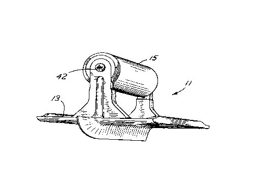
Referring to Figs. 1 and 2, a groover 11 includes a blade 13 and a wooden
handle
15. Blade 13 is die cast as a single metal piece from a zinc alloy. The die
casting
provides smooth metal surfaces.
p Blade 13 includes a central metal body member 17, generally rectangular in
shape
and having a bottom side 19 and a top side 21. Hottom side 19 includes a pair
of smooth
planar surfaces 23, 25, of like size, rectangular in shape, and being
coplanarly disposed.
Planar surfaces 23, 25 serve as concrete support surfaces, making contact with
the
concrete during use o,~ the groover.
Disposed between planar surfaces 23, 25 is a grooving bit 27. Bit 27 is
disposed
adjacent and contiguous to the inner edges 29, 31 of planar surfaces 23, 25,
respectively.
The bit is thus centrally located on the bottom side of the blade and extends
downwardly
(or outwardly) from planar surfaces 23, 25. Bit 27 is generally triangular in
cross-
section, as shown in Fig. 2, and extends longitudinally in length greater than
the
i 5 longitudinal length of surfaces 23, 25, as shown in Fig. 3. The front
portion 33 of bit 27
extends forwardly of the planar surfaces 23, 25 and curves upwardly along edge
34 to the
top side 21 as shown in Fig. 3. Front portion 33 converges to edge 34 in a
triangularly
cross-sectional shape, as shown in Fig. 4. Likewise, planar surfaces 23, 25
curve
upwardly at their front edge 35 (Fig. 3), to the top side 21.
'o Groover 11 has no raised lip (at the front edge 35) which extends above the
top
Surface 21. Referring to Fig. 4, the upper surface 36 of bit portion 33 is
coplanar with top
side 21 of the blade.
4
CA 02288564 1999-11-OS
Referring again to Fig. 3, a pair of posts 37, 39 extend upwardly from top
side 21
to support wood handle 15. Posts 37, 39 are integrally cast to central body
member 17
and are configured with smooth flaring edges where the posts meet with top
surface 21.
This allows ease of cleaning around the base of the posts.
Wood handle 15 is generally cylindrical in shape and of a size for providing a
gripping surface for the user's hand. The handle 15 is secured at each of its
ends to the
posts 37, 39, and its ends may be provided with a cutout groove to receive the
top of the
posts. Apertures 41, 43 are formed in the posts for receiving a securement
device, such
as a wood-type, metal screw 42 (Fig. 1 ), to secure the handle to the posts.
Handle 15 may
be formed of material other than wood, for example plastic, as will suggest
itself.
In addition, groover 11 may be a walking type groover. Handle 15 would be
eliminated in favor of a pole and bracket arrangement for allowing the user to
perform
the grooving by manipulating the pole.
Referring to Fig. 4, a pair of runners 45, 47 are disposed on the top side of
the
i: central body member and are integrally cast thereto. Runners 45, 47 run
parallel to the
outer edges 49, 51 of the blade and run parallel to the longitudinal axis of
the handle 15
and the bit 27. A runner surface 53 faces outwardly from the blade and is
disposed
substantially orthogonally to planar support surfaces 23, 25, as best seen in
Fig. 2.
Interior surfaces 53, 55, and 57 are flared to meet smoothly with top surface
21 to allow
?o ease of cleaning around the runners.
Metal blade 13 is die cast from a zinc alloy. For example, a Zamack 3 alloy
may
he used which is composed of 3.5 to 4.3% aluminum, 0.02 to 0.05% magnesium,
0.?5%
copper maximum, 0.1 °ro iron maximum, .U05% lead maximum and .004%
cadmium
5
CA 02288564 1999-11-OS
maximum, .003% tin maximum and the balance zinc. The term zinc alloy herein
means
an alloy substantially composed of zinc, i.e., where zinc is the primary
constituent of the
alloy.
While the invention has been particularly shown and described with rcfercncc
to
preferred embodiments thereof, it will be understood by those skilled in the
a.rt that
various modifications in form and detail may be made therein without depar.ing
from the
scope and spirit of the invention. Accordingly, modifications such as those
suggested
above. but not limited thereto are to be considered within the scope of the
invention.
For example. a grooving bit element may be attached to a conventional bull
float
to or fresno trowel. Such a grooving bit element is die cast from a Zinc alloy
and may
include integrally cast attachment components to permit securement of the bit
element to
the float or trowel. Such attachment components would include two brackets,
each
bracket being located at an end of the bit and configured as a channel for
securement to
the longitudinal sides of the l7oat or trowel.
~ 5 1n another example, a hand edger or a walking edger may be die cast from a
zinc
alloy. As understood, the hand edger includes a curved lip located at one
outer edge of
the blade and extends downward from a flat concrete support surface.
6