Sélection de la langue

Search

Sommaire du brevet 2290371 

Énoncé de désistement de responsabilité concernant l'information provenant de tiers

Une partie des informations de ce site Web a été fournie par des sources externes. Le gouvernement du Canada n'assume aucune responsabilité concernant la précision, l'actualité ou la fiabilité des informations fournies par les sources externes. Les utilisateurs qui désirent employer cette information devraient consulter directement la source des informations. Le contenu fourni par les sources externes n'est pas assujetti aux exigences sur les langues officielles, la protection des renseignements personnels et l'accessibilité.

Disponibilité de l'Abrégé et des Revendications

L'apparition de différences dans le texte et l'image des Revendications et de l'Abrégé dépend du moment auquel le document est publié. Les textes des Revendications et de l'Abrégé sont affichés :

  • lorsque la demande peut être examinée par le public;
  • lorsque le brevet est émis (délivrance).
(12) Demande de brevet: (11) CA 2290371
(54) Titre français: CONVOYEUR ET CHAINE POUR CONVOYEUR POUR SAUCISSES EN BOUCLES
(54) Titre anglais: CONVEYOR CHAIN AND SYSTEM FOR LOOPED SAUSAGE PRODUCTS
Statut: Réputée abandonnée et au-delà du délai pour le rétablissement - en attente de la réponse à l’avis de communication rejetée
Données bibliographiques
(51) Classification internationale des brevets (CIB):
  • B65G 17/20 (2006.01)
  • A22C 11/00 (2006.01)
  • A22C 15/00 (2006.01)
  • A23B 04/044 (2006.01)
  • A23B 04/052 (2006.01)
  • B65G 17/38 (2006.01)
(72) Inventeurs :
  • VELDKAMP, BRENT M. (Etats-Unis d'Amérique)
  • HAMBLIN, DAVID (Etats-Unis d'Amérique)
  • LEBSACK, KENNETH (Etats-Unis d'Amérique)
(73) Titulaires :
  • TOWNSEND ENGINEERING COMPANY
(71) Demandeurs :
  • TOWNSEND ENGINEERING COMPANY (Etats-Unis d'Amérique)
(74) Agent: SMART & BIGGAR LP
(74) Co-agent:
(45) Délivré:
(86) Date de dépôt PCT: 1999-03-29
(87) Mise à la disponibilité du public: 1999-10-07
Requête d'examen: 2000-12-13
Licence disponible: S.O.
Cédé au domaine public: S.O.
(25) Langue des documents déposés: Anglais

Traité de coopération en matière de brevets (PCT): Oui
(86) Numéro de la demande PCT: PCT/US1999/006847
(87) Numéro de publication internationale PCT: US1999006847
(85) Entrée nationale: 1999-11-12

(30) Données de priorité de la demande:
Numéro de la demande Pays / territoire Date
09/050,809 (Etats-Unis d'Amérique) 1998-03-30

Abrégés

Abrégé français

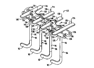
Cette chaîne pour convoyeur (112) pour chapelet de saucisses comporte plusieurs premiers porte-crochets (114) et plusieurs seconds porte-crochets (116) fixés pivotants aux premiers. Un crochet, généralement de forme en J (92), pourvu d'une tige allongée (94), est fixé à chacun des premiers et seconds porte-crochets par l'une des extrémités de sa tige. Un roulement à rouleaux (106) est monté rotatif sur cette extrémité de tige (94), mais uniquement sur celles assujetties aux seconds porte-crochets (116). Ces roulements à rouleaux (106) engrènent avec des dents (74) d'une roue dentée dont l'écartement est tel qu'elles n'entrent en prise qu'avec les tiges assujetties aux seconds porte-crochets (116) et ce, afin de les entraîner. Cette chaîne continue pour convoyeur (112) se trouve placée dans un compartiment de fumaison fermé (34) afin de soumettre les boucles de chapelets de saucisses (32) à l'action d'une substance à fumer, consistant en un liquide ou en de la fumée naturelle. Ce compartiment (34) comporte une série d'éléments rotatifs distincts (46, 48, 52, 58) dont certains sont des roues dentées entrant en prise avec la chaîne (112) et l'entraînant tandis que d'autres sont des éléments rotatifs (150, par exemple) pourvus d'une surface circulaire d'appui s'étendant autour d'eux afin d'entrer en contact avec des barres s'étendant latéralement (114) sur la chaîne à l'opposé des crochets (92). Les roues dentées (46, 52) sont disposées sur un plan horizontal tandis que les éléments rotatifs (58, 60) à surface d'appui le sont sur un plan vertical.


Abrégé anglais


A conveyor chain (112) for linked sausages has a plurality of spaced first
hook carriers (114) with second hook (116) carriers pivotally secured thereto
between pairs of the first hook carriers. A generally J-shaped hook (92)
having an elongated shank (94) is secured to each of the first and second hook
carriers by one of the ends of the shank. A roller bearing (106) is rotatably
mounted on that end of the shank (94) on only the shanks depending from the
second hook carriers (116). The roller bearings (106) engage teeth (74) on a
sprocket wheel spaced to operatively drivingly engage only the shanks
depending from the second hook carriers (116). The conveyor chain (112) is
continuous in nature and movably extends through an enclosed smoke compartment
(34) for subjecting the loops (32) of linked sausages to the smoke material,
either of a liquid nature, or natural smoke. The compartment (34) has a series
of spaced rotatable members (46, 48, 50, 52, 58), some of which are sprockets
(46) which engage and drive the chain (112), and others which are rotatable
members (e.g. 150) having a circular bearing surface extending therearound to
engage laterally extending bars (114) on the chain opposite to the hook
members (92). The sprocket members (46, 52) are disposed in a horizontal plane
and the rotatable members (58, 60) with the bearing surfaces are disposed in a
vertical plane.

Revendications

Note : Les revendications sont présentées dans la langue officielle dans laquelle elles ont été soumises.


What is claimed is:
1. A conveyor chain, comprising, a plurality of spaced first hook carriers
with second hook carriers pivotally secured thereto between pairs of said
first
hook carriers, a generally J-shaped hook having an elongated shank secured to
each of said first and second hook carriers by one of the ends of said shank,
and a roller bearing rotatably mounted on said one end of said shank on only
the shanks depending from said second hook carriers to engage teeth of a
sprocket wheel spaced to operatively drivingly engage only the shanks
depending from said second hook carriers.
2. The conveyor of claim 1 wherein said first hook carriers are each
comprised of a U-shaped member having spaced pairs of tabs extending
longitudinally from opposite ends thereof, with each pair of tabs being
pivotally secured about laterally extending axes to one of said second hook
carriers.
3. The conveyor chain of claim 2 wherein said second hook carriers are
each comprised of a pair of C-shaped clevice members pivotally secured to each
other and each secured to a shank depending from the second hook carrier,
with each of said clevice members being pivotally secured to an adjacent first
hook carrier about a laterally extending axis.
4. The conveyor chain of claim 3 wherein a laterally extending bar is
secured to said one end of each of said shanks.
5. The conveyor chain of claim 1 wherein the shanks depending from each
of said first hook carriers are rigidly secured to said first hook carriers.
6. The conveyor chain of claim 3 wherein the shanks depending from each
of said second hook carriers are rigidly secured to one of said clevice
members.
8

7. A conveyor system, comprising, a frame, a series of spaced rotatable
members on said frame, a continuous conveyor chain extending around said
rotatable members, power means on said frame for rotating at least one of said
rotatable members to movingly drive said chain, said chain comprising a
plurality of spaced first hook carriers with second hook carriers pivotally
secured thereto between pairs of said first hook carriers, a generally J-
shaped
hook having an elongated shank secured to each of said first and second hook
carriers by one of the ends of said shank, at least one of said rotatable
members being a sprocket having radially extending spaced teeth, said teeth
being so spaced to operatively drivingly engage only the shanks depending
from said second hook carriers.
8. The conveyor system of claim 8 wherein said sprocket is disposed in a
plane at right angles to a longitudinal axes of said shanks.
9. The conveyor system of claim 8 wherein a laterally extending bar is
secured to said one end of each of said shanks, at least one of said rotatable
members having a circular bearing surface extending around an outer
periphery thereof, said chain extending partially around said bearing surface
with said laterally extending bars engaging said bearing surface.
10. The conveyor system of claim 9 wherein said circular bearing surface is
rotatable around a horizontal axis.
11. The conveyor system of claim 9 wherein said bearing surface rotates
about a horizontal axis.
12. The conveyor system of claim 10 wherein said circular bearing surface is
rotatable around a horizontal axis and the plane of said rotatable member is
in
a vertical position.
9

13. The conveyor system of claim 12 wherein said rotatable members
include two of said bearing surfaces in a vertical plane, and include four of
said
sprockets in a horizontal plane.
14. The device of claim 7 wherein said conveyor system is enclosed within a
sausage smoke compartment.
15. The device of claim 1 wherein said conveyor system is enclosed within a
sausage smoke compartment.
10

Description

Note : Les descriptions sont présentées dans la langue officielle dans laquelle elles ont été soumises.


CA 02290371 1999-11-12
WO 99/x9737 PCT/US99/06847
TITLE: CONVEYOR CHAIN AND SYSTEM FOR
LOOPED SAUSAGE PRODUCTS
BACKGROUND OF THE INVENTION
Elongated strands of looped sausage links are typically subjected to
liquid or natural smoke after being formed on a sausage making machine. The
smoke environment is intended to impart flavor to the sausage. See such a
machine disclosed in U.S. Patent No. 4,532,858. The sausage strand is draped
over hooks on a conveyor which is rotated through a smoke compartment
to where a spray of liquid smoke, or natural smoke, is present. The conveyor
includes a continuous conveyor chain which moves through the compartment
in more than one plane.
The problem with the existing conveyor chains is that the hooks thereon
are substantially spaced to accommodate the turns in the circuitous path of
the
~s chain as it moved through the housing, thus decreasing the product density
of
the system. Further, it is not readily possible to position the hooks closer
together because this would not allow the chain to easily follow a dual plane
path within the confines of the housing.
It is therefore a principal object of this invention to provide a conveyor
2o chain and system for looped sausage products which will increase the
density
(volume) of sausage links, and at the same time, permit the conveyor to easily
move through a circuitous dual-plane path within the smoke compartment.
These and other objects will be apparent to those skilled in the art.
2s SUMMARY OF THE INVENTION
A conveyor chain for linked sausages has a plurality of spaced first hook
carriers with second hook carriers pivotally secured thereto between pairs of
the first hook carriers. A generally J-shaped hook having an elongated shank
is secured to each of the first and second hook carriers by one of the ends of
the
3o shank. A roller bearing is rotatable mounted on that end of the shank on
only
the shanks depending from the second hook carriers. The roller bearings

CA 02290371 1999-11-12
WO 99149737 PCT/US99/06847
engage teeth on a sprocket wheel spaced to operatively drivingly engage only
the shanks depending from the second hook carriers.
The conveyor chain is continuous in nature and movably extends
through an enclosed smoke compartment for subjecting the loops of linked
s sausages to the smoke material, either of a liquid nature, or natural smoke.
.
The compartment has a series of spaced rotatable members, some of which are
sprockets which engage and drive the chain, and others which are rotatable
members having a circular bearing surface extending therearound to engage
laterally extending bars on the chain opposite to the hook members. The
Io sprocket members are disposed in a horizontal plane and the rotatable
members with the bearing surfaces are disposed in a vertical plane.
BRIEF DESCRIPTION OF THE DRAWINGS
Fig. 1 is a perspective view of a prior art conveyor chain;
is Fig. lA is an exploded view of one of the hook assemblies of Fig. 1;
Fig. 1B is an exploded top plan view of the assembly of Fig. lA;
Fig. 1C is an exploded side elevational view of the hook assembly of 1B
as seen from the bottom thereof;
Fig. 2 is a side elevational view of the prior art chain of Fig. 1;
2o Fig. 3 is a top plan view of the type of prior art chain shown in Figs. 1
and 2;
Fig. 4 is perspective view of the conveyor chain of this invention;
Fig. 4A is an exploded perspective view of one of the hook assemblies of
Fig. 4;
2s Fig. 4B is an exploded top plan view of the hook assembly of Fig. 4A;
Fig. 4C is an exploded side elevational view of the hook assembly of 4B
as seen from the bottom thereof;
Fig. 5 is a side elevational view of a portion of the chain shown in Fig. 4;
Fig. 6 is bottom plan view of the chain shown in Fig. 4 disposed in an
3o arcuate position;
2

CA 02290371 1999-11-12
WO 99149737 PCT/US99/06847
Fig. 6A is a top plan view of the chain shown in Fig. 4 disposed in an
arcuate position;
Fig. 7 is a bottom plan view similar to Fig. 6 wherein the teeth of a
sprocket are shown in dotted lines;
s Fig. 8 is a plan view of the sprocket used in conjunction with the chain
of Figs. 4-7;
Fig. 9 is a sectional view taken on line 9-9 of Fig. 8; Fig. 10 is a
plan view of a rotatable member forming a part of the support mechanism for
the chain of Figs. 4-7; Fig. 11 is a sectional view taken on line 11-11 of
Fig.
to 10;
Fig. 12 is a schematic plan view of a portion of the conveyor system of
this invention;
Fig. 13 is a schematic perspective view showing the rotatable members
used in this invention; and
t 5 Fig. 14 is perspective view of a sausage making machine and the smoke
compartment which houses the conveyor system of this invention.
DESCRIPTION OF THE PREFERRED EMBODIMENT
With reference to Fig. 14, a conventional sausage making machine 10
2o has a frame 12 with four supporting legs 14. The top 16 of frame 12
supports a
conventional stung tube 18, a meat emulsion pump 20, a casing hopper 22, a
linker housing 24 which houses a conventional linker (not shown), a computer
control 26, and a conventional discharge horn 28. Links of sausage 30 formed
into loops 32 are shown being conventionally discharged from horn 28. The
25 foregoing structure is conventional and does not, per se, constitute a part
of
this invention.
A conventional smoke compartment 34 has an entry door 36 and an exit
door 38. The entry and exit doors 36 and 38 are located in sidewall 40. A
substantially horizontal chain guide 42 is affixed to sidewall 40 as is a
chain
3o shield 44. With reference to Fig. 13, sprocket wheels 46, 48, 50 and 52 are
identical and are mounted in a horizontal plane on vertical shafts 54 in any
3

CA 02290371 1999-11-12
WO 99/49737 PCT/US99/06847
convenient manner. These sprocket wheels 46-52 are mounted within smoke
compartment 34. An electric gear motor 56 is operatively connected to
sprocket 46 and is adapted to rotate sprocket 46 in conventional fashion.
Pulleys 58 and 60 are mounted on horizontal shafts 62 on the outside of
s sidewall 40 with the sprocket 58 dwelling within shield 44.
With reference to Figs. 8 and 9, which specifically shows sprocket 46
which is identical to sprockets 48-52, a hub 64 is located in the center
thereof
and is secured to a center opening in the sprocket by a connecting bolt 65.
Hub
64 has a center bore 66 and a plurality of arms 68 extending radially
outwardly therefrom. The arms 68 terminate in a circular rim portion 70
which has an outer surface 72. A plurality of teeth 74 extend radially
outwardly from the outer surface 72 (Fig. 8) and terminate in a U-shaped
notch 76. As shown in Fig. 13, all four of the identical sprockets 46-52 are
in a
horizontal plane and are in the same plane with each other. The rotatable
~5 member 58 is shown in Figs. 10 and 11 and is similar to the member 60
except
that the diameter of member 58 is greater than the diameter of the member
60. The member 58 has a hub 78 with a center bore 79 adapted to receive
horizontal shaft 62 (Fig. 13). A center web 80 extends outwardly from hub 78
and terminates in a rim 82 which has a flat circular bearing surface 84.
2o With reference to Figs. 1-3, a conventional prior art chain 86 is shown
which includes a hook carrier 88. The carrier 88 includes a J-shaped hook 90
which has a J-shaped portion 92 at its lower end. An elongated shank 94
extends from the J-shaped portion 92 upwardly towards the hook carrier 88.
With particular reference to Figs. 1, lA, 1B, and 1C, the carrier 88 has two
2s components: a small clevice 96 and a larger clevice 98. Each clevice has a
vertical base or wall 100. Each clevice 96 and 98 has a pair of horizontally
disposed tabs 102 and 102A, respectively, extending horizontally outwardly
from the base wall 100. A flat bar 104 extends laterally outwardly from the
upper tab 102 on member 96. The upper end of hook shank 94 extends
3o upwardly through an aperture in the lower tab 102 and terminates by
swedging or the like at the center of bar 104. As seen in Fig. 1, a rotatable
4

CA 02290371 1999-11-12
WO 99!49737 PCTNS99l06847
bearing 106 is mounted on the upper end of shank 94 in the space between the
lower tab 102A and the bar 104.
A pin 108 (with bushing 109 thereon) pivotally connects spaced tabs 110
and 110A. Those tabs are vertically disposed and extend outwardly from base
walls 100 of members 96 and 98 in a direction towards each other. Tabs 102A
are received between the tabs 110 of member 96. Again, pin 108 extends
through registering apertures in the tabs 110 and 110A to pivotally secure the
members 96 and 98 together.
While the prior art structure of Figs. 1 through 3 is usable, the
1o substantial space between the shanks 94, as caused by the members 96 and
98, substantially reduces the number of loops of sausage that can be carried
by
the chain 88.
The chain system of this invention is thus shown in Figs 4-7. With
reference to Fig. 4, the chain 112 is comprised of a first hook carrier 114
and a
~5 second hook carrier 116. The hook carrier 114 includes a U-shaped bracket
118 having a bottom 120 and sides 122. A pair of vertically disposed tabs 124
extend longitudinally outwardly from one side of walls 122. A similar pair of
tabs 126 are also disposed in a vertical plane and extend outwardly in a
direction opposite to tabs 124. A cross bar 128 is rigidly secured to the
upper
2o ends of sidewalls 122 and extends in a lateral direction from bracket 118.
A C-shaped clevice 130 (Fig. 4C) has a vertical base wall 132 with
horizontally disposed upper tabs 134 and 136 extending outwardly from wall
132. A horizontal cross bar 138 extends laterally outwardly from tab 134.
Cross bar 138 is essentially identical to cross bar 128. A pair of tabs 140
dwell
25 in a vertical plane and extend towards the tabs 126 of member 114. Tabs 140
are pivotally fitted within the tabs 124 and are pivotally connected together
by
pins 141. (Fig. 4). The above described C-shaped device 130 comprises one of
the two components of the second hook carrier 116.
The second component of hook carrier 116 is comprised of a compound
3o clevice 142 (Fig. 4A) which has a normally vertically extending base wall
144.
A pair of tabs 146 dwell in a horizontal plane and extend towards the tabs 134

CA 02290371 1999-11-12
WO 99!49737 PCT/US99/06847
and 136 on clevice 130. Tabs 146 slidably and pivotally fit within the tabs
134
and 136 on clevice 130. A second pair of tabs 148 dwell in a vertical plane
and
extend from base wall 144 in a direction opposite to that of tabs 146.
Again, the upper ends of all of the shanks 94 are rigidly secured to the
centers of lateral extending bars 128 or 138. The upper ends of the shanks
extend through suitable apertures in the lower tab member of the hook
carriers 114 and 116. It is important to note that there are bearings 150 on
the upper ends of the shanks only which depend from the second hook carrier
116 and not the hook carrier 114. It should also be noted that the hooks 90 in
to the embodiment in Figs. 4-7 are much closer together than are the hook
elements in the prior art device of Figs. 1 through 3.
In the normal operation of the device of this invention, (Fig. 14) the
loops of the sausage strand are created as the hooks 90 intercept the links 30
at predetermined points. The loops 32 are carried into the entry door 36 and
~5 are subjected to a shower of smoke generally located at the end 152 of
compartment 34. The general area designated by the numeral 154 represents
the area where the sausage loops are permitted to dry or at least lose some of
the excess liquid smoke imposed upon the loops.
The path of the loops through the compartment 34 is best shown by the
2o dotted lines in Fig. 13. As soon as the loops enter the door 36, their
direction
is reversed as the chain 88 moves around sprocket 50 and back towards the
sprocket 52. The direction of the chain is thereupon reversed and the loops
are
moved back towards the sprocket 46. Upon departing sprocket 46 the chain
moves then towards the sprocket 48 which moves the chain through the exit
25 opening 38 towards the rotatable member 58. The member 58 moves the chain
vertically upward and back towards a place of beginning to rotatable member
60. When in the last phase of this path, the chain moves on chain guide 42 on
the outside of the compartment 34 as shown in Fig. 14.
The device for imparting liquid smoke or natural smoke to the length of
3o chain in the area 152 has not been shown for this is conventional and does
not
per se comprise a part of this invention.
6

CA 02290371 1999-11-12
WO 99L49737 PCT/US99/06847
From the foregoing, it is seen that the closely located hooks 90 will
substantially increase the volume or density of loops that can be treated in
the
smoke compartment 34 through one pass of the chain 88. Further, since the
sprockets 42 through 48 are substantially spaced and engage the roller
bearings 150 which are mounted only on every other hook, the chain 88 is
easily moved from one plane to another within the compartment 34.
It is therefore seen that this invention will achieve at least all of its
stated objectives.

Dessin représentatif
Une figure unique qui représente un dessin illustrant l'invention.
États administratifs

2024-08-01 : Dans le cadre de la transition vers les Brevets de nouvelle génération (BNG), la base de données sur les brevets canadiens (BDBC) contient désormais un Historique d'événement plus détaillé, qui reproduit le Journal des événements de notre nouvelle solution interne.

Veuillez noter que les événements débutant par « Inactive : » se réfèrent à des événements qui ne sont plus utilisés dans notre nouvelle solution interne.

Pour une meilleure compréhension de l'état de la demande ou brevet qui figure sur cette page, la rubrique Mise en garde , et les descriptions de Brevet , Historique d'événement , Taxes périodiques et Historique des paiements devraient être consultées.

Historique d'événement

Description Date
Inactive : CIB de MCD 2006-03-12
Demande non rétablie avant l'échéance 2005-03-29
Le délai pour l'annulation est expiré 2005-03-29
Réputée abandonnée - les conditions pour l'octroi - jugée non conforme 2004-06-08
Réputée abandonnée - omission de répondre à un avis sur les taxes pour le maintien en état 2004-03-29
Inactive : Taxe finale reçue 2003-12-31
Un avis d'acceptation est envoyé 2003-12-08
Lettre envoyée 2003-12-08
Un avis d'acceptation est envoyé 2003-12-08
Inactive : Approuvée aux fins d'acceptation (AFA) 2003-11-18
Modification reçue - modification volontaire 2003-10-07
Inactive : Dem. de l'examinateur par.30(2) Règles 2003-07-04
Lettre envoyée 2001-01-05
Toutes les exigences pour l'examen - jugée conforme 2000-12-13
Requête d'examen reçue 2000-12-13
Exigences pour une requête d'examen - jugée conforme 2000-12-13
Lettre envoyée 2000-03-02
Inactive : Transfert individuel 2000-02-17
Inactive : CIB attribuée 2000-01-20
Inactive : CIB enlevée 2000-01-20
Inactive : CIB en 1re position 2000-01-20
Inactive : Page couverture publiée 2000-01-13
Inactive : CIB attribuée 2000-01-11
Inactive : CIB en 1re position 2000-01-11
Inactive : Lettre de courtoisie - Preuve 1999-12-29
Inactive : Notice - Entrée phase nat. - Pas de RE 1999-12-23
Demande reçue - PCT 1999-12-17
Demande publiée (accessible au public) 1999-10-07

Historique d'abandonnement

Date d'abandonnement Raison Date de rétablissement
2004-06-08
2004-03-29

Taxes périodiques

Le dernier paiement a été reçu le 2003-02-20

Avis : Si le paiement en totalité n'a pas été reçu au plus tard à la date indiquée, une taxe supplémentaire peut être imposée, soit une des taxes suivantes :

  • taxe de rétablissement ;
  • taxe pour paiement en souffrance ; ou
  • taxe additionnelle pour le renversement d'une péremption réputée.

Les taxes sur les brevets sont ajustées au 1er janvier de chaque année. Les montants ci-dessus sont les montants actuels s'ils sont reçus au plus tard le 31 décembre de l'année en cours.
Veuillez vous référer à la page web des taxes sur les brevets de l'OPIC pour voir tous les montants actuels des taxes.

Historique des taxes

Type de taxes Anniversaire Échéance Date payée
Taxe nationale de base - générale 1999-11-12
Enregistrement d'un document 2000-02-17
Requête d'examen - générale 2000-12-13
TM (demande, 2e anniv.) - générale 02 2001-03-29 2001-03-12
TM (demande, 3e anniv.) - générale 03 2002-03-29 2002-03-01
TM (demande, 4e anniv.) - générale 04 2003-03-31 2003-02-20
Titulaires au dossier

Les titulaires actuels et antérieures au dossier sont affichés en ordre alphabétique.

Titulaires actuels au dossier
TOWNSEND ENGINEERING COMPANY
Titulaires antérieures au dossier
BRENT M. VELDKAMP
DAVID HAMBLIN
KENNETH LEBSACK
Les propriétaires antérieurs qui ne figurent pas dans la liste des « Propriétaires au dossier » apparaîtront dans d'autres documents au dossier.
Documents

Pour visionner les fichiers sélectionnés, entrer le code reCAPTCHA :


Pour visualiser une image, cliquer sur un lien dans la colonne description du document. Pour télécharger l'image (les images), cliquer l'une ou plusieurs cases à cocher dans la première colonne et ensuite cliquer sur le bouton "Télécharger sélection en format PDF (archive Zip)" ou le bouton "Télécharger sélection (en un fichier PDF fusionné)".

Liste des documents de brevet publiés et non publiés sur la BDBC .

Si vous avez des difficultés à accéder au contenu, veuillez communiquer avec le Centre de services à la clientèle au 1-866-997-1936, ou envoyer un courriel au Centre de service à la clientèle de l'OPIC.


Description du
Document 
Date
(aaaa-mm-jj) 
Nombre de pages   Taille de l'image (Ko) 
Dessin représentatif 2000-01-12 1 14
Description 2003-10-06 7 337
Revendications 2003-10-06 4 124
Abrégé 1999-11-11 1 72
Description 1999-11-11 7 352
Revendications 1999-11-11 3 108
Dessins 1999-11-11 11 307
Avis d'entree dans la phase nationale 1999-12-22 1 195
Courtoisie - Certificat d'enregistrement (document(s) connexe(s)) 2000-03-01 1 115
Accusé de réception de la requête d'examen 2001-01-04 1 180
Rappel de taxe de maintien due 2000-11-29 1 112
Avis du commissaire - Demande jugée acceptable 2003-12-07 1 160
Courtoisie - Lettre d'abandon (taxe de maintien en état) 2004-05-24 1 175
Courtoisie - Lettre d'abandon (AA) 2004-08-16 1 166
Correspondance 1999-12-22 1 15
PCT 1999-11-11 3 119
Taxes 2003-02-19 1 32
Correspondance 2003-12-30 1 34
Correspondance 2004-01-15 1 11
Correspondance 2004-01-15 5 162
Taxes 2001-03-11 1 33
Taxes 2002-02-28 1 32