Note : Les descriptions sont présentées dans la langue officielle dans laquelle elles ont été soumises.
CA 02290540 1999-11-18
WO 98/56872 PCT/US98/11902
PYROLYSIS FURNACE WITH AN INTERNALLY FINNED U-SHAPED
RADIANT COIL
Field of the Invention
The present invention relates to a fired heater for heating process
fluids, e.g., process heaters. More specifically, it relates to a fired heater
of
the type which comprises at least one radiant section in which process fluid
flowing through tubes therein is indirectly heated, preferably, by radiant
energy provided by burners. The methods and apparatus used in accordance
with the present invention are particularly well suited and advantageous for
pyrolysis of normally liquid or normally gaseous aromatic and/or aliphatic
hydrocarbon feedstocks such as ethane, propane, naphtha or gas oil to
produce ethylene and other by products such as acetylene, propylene,
butadiene, etc. Accordingly, the present invention will be described and
explained in the context of hydrocarbon pyrolysis, particularly steam cracking
to produce ethylene.
Background of the Invention
Steam-cracking is the predominant commercial method for producing-
light olefins such as ethylene, propylene and butadiene. Ethylene, propylene,
and butadiene are basic building block chemicals used in the manufacture of
high volume poiymeric materials and commercially important chemical
intermediates. The demand for these basic building block petrochemicals is
expected to continue to grow in the foreseeable future. Of the products
produced in steam cracking, ethylene has the highest demand, and is the
most costly to separate and purify. Therefore improving the yield or
selectivity of ethylene is highly desired. Steam cracking involves a thermal
cracking reaction typically carried out in a fired tubular reactor. Reactor
selectivity to ethylene is favored by short residence time and low hydrocarbon
partial pressures. Hydrocarbon feeds ranging from ethane to vacuum gas-oil
are used, and the reaction is conducted in the presence of dilution steam.
CA 02290540 1999-11-18
WO 98/56872 PCT/US98/11902
-2-
The complex reactions and the tubular reactor are extensively discussed in
both public domain literature and numerous patents.
Steam cracking of hydrocarbons has typically been effected by
supplying the feedstock in vaporized or substantially vaporized form, in
admixture with substantial amounts of dilution steam, to suitable coils in a
cracking fumace. It is conventional to pass the reaction mixture through a
number of parallel coils or tubes which pass through a convection section of
the cracking furnace wherein hot combustion gases raise the temperature of
the feed and dilution steam. Each coil or tube then passes through a radiant
section of the cracking furnace wherein a multiplicity of burners supply the
heat necessary to bring the reactants to the desired reaction temperature and
effect the desired reaction.
Of primary concern in all steam cracking process configurations is the
formation of coke. When hydrocarbon feedstocks are subjected to the
heating conditions prevalent in a steam cracking furnace, coke deposits tend
to form on the inner walls of the tubular members forming the cracking coils.
Such coke deposits interfere with heat flow through the tube walls into the
stream of reactants, which results in higher tube metal temperatures,
ultimately reaching the limits of the tube metallurgy. Additionally, the coke
deposits interfere with the flow of the reaction mixture resulting in higher
pressure drop, due to reduced tube cross sectional area.
The optimum way of improving selectivity to ethylene was found to be
by reducing coil volume while maintaining the heat transfer surface area.
This has been accomplished by replacing large diameter, serpentine coils
with a mu"-oIicity of smaller diameter tubes having a greater surface-to-
volume rati;J- than the large diameter tubes. The tubes typically have inside
diameters up to about 7.6 cm (3 inches), generally from about 3.0 cm to 6.4
cm (1.2 to 2.5 inches).
CA 02290540 1999-11-18
WO 98/56872 PCT/US98/11902
-3-
The desire for short residence times has led to the use of shorter coils,
typical lengths being progressively reduced over the years from over 45 m
(150 ft.) to 20m - 27m (60-90 ft.) and more recently 9m - 12m (30-40 ft). As
coils have been reduced in length, it has been necessary to reduce the tube
diameter in an effort to reduce the heat flux and hence the tube metal
temperatures. Current cracking coils are generally constructed from high
alloy (25% Cr, 35% Ni, plus additives) austenitic stainless steels, and are
operated at maximum tube metal temperatures in the range 1030 - 1150
degrees C (1900-2100 degrees F).
Despite the significant evolution of cracking furnace design, the
process is still limited by the fact that it makes as a byproduct coke, which
deposits on the inside of the coils. The coke acts as an insulator, and hence
increases the tube metal temperatures of the coil. When the tube metal
temperature reaches the maximum capability of the material it is necessary to
cease production and decoke the furnace. This is generally carried out by
passing a mixture comprising air and steam through the coils at high
temperature. * The coke is removed by a combination of combustion and
erosion/spalling. Other decoking techniques which avoid the use of air are
also used in the industry. In this case the coke is removed primarily by
erosion/spalling and gasification. Regardless of the decoking technique that
is used some of the spalled coke is in the form of large particles. As tube
diameters have decreased the likelihood of large coke particles plugging the
coil before or during decoking have increased. Decoking typically takes from
12 -48 hours, depending on a variety of factors including: the furnace design,
the feed that was cracked, the operating time before the decoke, and the
cracking severity employed.
Technology to reduce tube metal temperatures (and hence coking
rates, or altematively to allow a shorter residence time coil to be used) has
been widely sought by the industry. Some designers have resorted to
CA 02290540 1999-11-18
WO 98/56872 PCT/US98/11902
-4-
multiple inlet leg coils to reduce the heat flux on outlet tubes (e.g.; EP 0
305
799 Al). Others have attempted to prevent the formation of the insulating
coke layer inside the tube by adding small concentrations of specific elements
to the reactor feed.
Heat transfer to the highly endothermic cracking reaction may be
represented by the familiar equation Q = UxAxaT. U, the heat transfer
coefficient is a function of the gas velocity inside the tube. Higher
velocities
increase U, and hence reduce the required AT (temperature difference) thus
reducing tube metal temperature for a given process fluid temperature.
However, as velocities increase, pressure drop increases, increasing the coil
average hydrocarbon partial pressure. Eventually the pressure effect over-
rides the effect of reduced residence time, and further increases in velocity
reduce reactor selectivity to ethylene. This represents a maximum practical
value to U.
Overall area (A) may be increased by using multiple small diameter
tubes. This trend has been pursued by the industry, resulting in reactors with
tubes of inside diameter 2.5 cm - 3.8 cm (1.0 - 1.5 inch). This represents a
minimum practical diameter due to manufacturing limitations, and below these
diameters the effects of coke build-up inside the tube becomes excessive.
The general principle of increasing internal surface area to improve
heat transfer is well known in the general heat transfer art. However,
applying this principle to very high temperature coking services like steam
cracking is difficult.
Nevertheless, this method of improving heat transfer to reduce the
tube metal temperatures in steam cracking furnaces has been proposed in
several varieties. One example (US 4,342,242) uses a specially designed
longitudinal insert in an otherwise circular tube cross section. The insert
has
a central body and outwardly extending vanes which contact the interior of the
coil. In this particular disclosure the insert is positioned in only a portion
of
CA 02290540 1999-11-18
WO 98/56872 PCT/US98/11902
-5-
the overall tubular coil in the furnace. Another example (GB 969,796) utilizes
intemaliy rounded channels or fins which enhance the inside area. The
intemal profile was smooth to avoid stress concentrations and flow
disturbances. The specific tubes described in this disclosure made 4 passes
through the radiant section and had a relatively large 9.525 cm (3.75 inch)
inside diameter.
Variations of this rounded intemal channels or finned tube profile have
been applied commercially in specific coil designs. A paper presented at an
American Institute of Chemical Engineers Meeting ("Specialty Furnace Design
Steam Reformers and Steam Crackers" by T.A. Wells, presented at the 1988
AIChE Spring National Meeting, New Orleans, Louisiana, March 6-10, 1988)
discloses the use of a type of extended internal surface tube in a single tube
pass design. The inlet legs of longer coils (EP 0 305 799 Al) and a literature
reference for this design , denominated SRT V (Energy Progress Vol. 8, No.
3, p. 160-168 , Sept. 1988) have utilized internal extended surface. In both
of
the latter cases the commercial use was based on tubes of approximately 2.5
- 3.8 cm (1.0 - 1.5 inch) inside diameter and where the tube section that had
the rounded internal channels or fins made only a single pass through the
fumace radiant section. Another literature reference ("USC Super U Pyrolysis
Concept" by David J. Brown, John R. Brewer and Colin P. Bowen presented
at the AIChE Spring National Meeting in Orlando, Florida, March 1990)
presents data on tubes with internal fins on the inlet leg. This reference
speculates that providing fins on the outlet leg would be beneficial, however
it
provides no suggestion as to what operating or design parameters would be
required to successfully demonstrate or enable the use of fins on the outlet
leg.
However, an extended internal surface design to this time, has not
been shown to be feasible in two pass coils typically made up of U shaped
tubes. These two pass coils are typically 15m - 27m (50 - 90 ft.) in total
~ CA 02290540 1999-11-18
WO 98/56872 PCT/US98/11902
-6-
iength, with intemal diameters in the range 3.8 cm - 6.4 cm (1.5 - 2.5 inch).
Two pass coils can be as short as 13m (40ft). One problem is that the
capability to make an internally finned tube long enough to form the complete
U shaped tube does not exist.
An internally finned tube could be used just for the inlet half of the U
shaped tubes, as described in EP 0 305 799 Al which uses internal fins,
studs or inserts only on the inlet tubes to the fumace - not the outlet. This
reference discloses that inserts located in the outlet tube would be expected
to act as nucleus for the growth of the coke formed during pyrolysis.
However, the highest tube metal temperatures occur near the outlet end, so
the advantageous effect of the finned tube is not applied to where it is most
needed. Applying the finned tube to the outlet leg of the coil would be
possible, but it carries the risk that coke pieces from the inlet leg could
break
loose and become lodged at the start of the finned section. Finally, the
industry conventional wisdom suggested that a bent finned tube section
would be prone to plugging with coke spalled from the inlet leg of the coil.
In light of the known deficiencies in heat transfer in steam cracking
furnaces there is a need for a means to increase the heat transfer in the
inside of the tubes to reduce coking, tube metal temperature and improve
ethylene selectivity. Particularly, it would be highly desirable to have a
design
for a 2 pass coil or U shaped tubes that uses some means of increased
internal surface area to reduce tube metal temperature throughout its entire
length.
Summary of the Invention
The present ir:.7.,ntion is directed towards a fired heater for heatirtiy a
process fluid that provides increased internal heat transfer surface to reduce
tube metal temperatures at the inlet and outlet of a U shaped tube and at the
same time is not prone to plugging from coke. The fired heater comprises a
radiant section enclosure having a plurality of U shaped tubes disposed
CA 02290540 1999-11-18
-7-
= =, ,
.. ... , ,. ..
therein, . , .
an inlet for introducing the process fluid into the U shaped tubes,
bumers for exposing the external surface of the U shaped tubes to radiant
heat, an outlet for cooling and collecting the process fluid from the U shaped
tubes, wherein the U shaped tubes are formed by connecting one or more
tubular. sections; and at least the outlet leg of the U shaped tubes are
provided with internal generally longitudinal fins. In another embodiment the
entii-e length of the U shaped tubes are provided with intemal generally
longitudinal fins.
Drawings
These and other features, aspects and advantages of the present
invention will become better understood with regard to the following drawings,
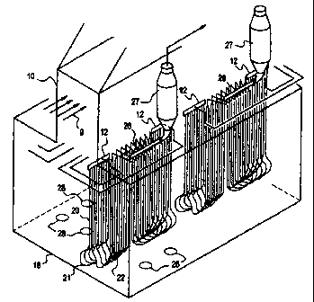
description and appended claims. Figure 1 represents a three dimensional
drawing of a steam cracking furnace showing a typical arrangement of
internals. Figure 2 shows a single U shaped furnace tube. Figure 3 shows a
cross section of finned U shaped furnace tubes.
Detailed Description of the Invention
The present invention describes a fired heater for heating a process
fluid. More particularly the invention is directed towards a fired heater
heating
a process fluid which is prone to forming coke as a result of chemical
reactions occurring as a result of the heating. A specific embodiment of the
invention is a steam cracking fumace employed in the petrochemical industry
to manufacture olefins.
Referring to Fig. 1 the feed stream 9 enters the convection section 10,
through one or more inlet lines 9 where it is preheated preferably to a
temperature from about 800 F (426 C) to 1500 F (816 C) by hot combustion
gases which gases are preferably are at a temperature from about 1500 F
(816 C) to about 2400 F (1316 C), before it enters the radiant section inlet
distributor 12. From the radiant section inlet distributor 12 the preheated
feed
enters the U shaped
AMENDED SHEET
CA 02290540 1999-11-18
= . . ... .,.
-8- = . .
.. ..
tubes 14 (hereinafter referred to as U tubes) which are situated inside the
radiant section enclosure 16, also known in the art as the radiant box.
The radiant section enclosure 16 is typically lined with heat insulating
refractory material to conserve heat energy.
The radiant section enclosure includes a plurality of U tubes. The end
of the U tubes which are connected to one or more feed inlet distributors 12
which introduce the process fluid into the U tubes are called inlet legs 20.
The opposite end of each of the U tubes 22 called the outlet leg is connected
to an outlet header 26 for collecting the process fluid after it has been
heated
and the thermal cracking reactions have occurred. The temperature of the
process fluid is typically from about 1300 F (816 C) to about 2000 F (1093 C)
leaving the outlet leg of the U tube. From there the process fluid is passed
to
quench exchanger 27 which cool the process fluid to stop the thermal cracking
reactions. In another embodiment, not depicted in Figure 1, the outlet leg of
each U tubes is directly connected to an individual quench exchanger to cool
the process fluid. The outlet from each individual quench exchanger is then
connected to an outlet header. Such an arrangement is know in the art as a
close coupled transfer line exchanger. In yet another embodiment not
depicted in Figure 1, the outlet leg of each U tube is connected to a quench
point whereby the process fluid is directly contacted with a quench liquid
which vaporizes to cool the process fluid.
For the purposes of this invention U tubes are shaped somewhat like
the letter "U" when viewed in a two dimensional drawing such as Figure 2. A
defining characteristic is that the U tube makes effectively 2 passes through
the radiant enclosure. The U tubes are comprised of an inlet leg 20, an outlet
leg 22, and a curved or bent portion 21 connecting the inlet leg 20 and the
outlet leg 22. In other embodiments the outlet leg can be comprised of one or
more branched portions. In yet other preferred embodiments the inlet leg 20
can be comprised of more than one branched tube. There are a variety of
AMENDED SHEET
CA 02290540 1999-11-18
WO 98/56872 PCT/US98/11902
-9-
ways known in the art of arranging a plurality of U tubes in a radiant
enclosure. Those skilled in the art. will consider spatial arrangement,
location
of the bumers, location of the inlet header and outlet means, and thermal
stresses on the U tubes themselves in choosing the arrangement. In some
arrangements each of the individual U tubes lies in a single plane. In other
arrangements the U tubes are bent out of plane. All such arrangements are
contemplated as U tubes for the purposes of this invention.
The radiant section enclosure contains a plurality of bumers 28 for
exposing the external surface of the U shaped tubes to radiant heat. A wide
variety of burner types known in the art can be used including raw gas or pre-
mixed burners. Recent designs have additionally used a variety of flue gas
recirculation techniques to reduce NOx formation for environmental reasons.
The combustion air source can be from ambient air, preheated air or from gas
turbine exhaust.
The total length of the U tubes is preferably 20m - 27m (60 - 90 ft).
Since it is difficult to manufacture the internally finned tubes in the
desired
20m - 27m (60 - 90 ft) length, two sections might need to be connected with
at least one intermediate weld. As described in US 4,827,074 intermediate
welds are known to be a potential source of accelerated coke deposition. In
one preferred embodiment this potential coke deposition is minimized in U
tubes with one intermediate weld at the bottom of curved portion of the U and
arranging the U tubes such that the weld is shielded from direct radiation by
the adjacent tubes. In another embodiment the weld area may be wrapped
by insulating material.
The internally finned tubes can be successfully bent to the radius
required at the bottom of the U tube using either well-known cold-bending, or
hot-induction bending techniques.
Whether the U tubes are formed by connecting two or more tubular
sections or are formed in one piece, preferably the entire iength of the
finned
CA 02290540 1999-11-18
WO 98/56872 PCT/US98/11902
-10-
U tubes are provide with intemal generally longitudinal fins. Another
embodiment would provide the fins on the outlet leg only. In yet another
embodiment the fins are provided in the curved portion of the U tube and the
outlet leg.
Figure 3 shows a cross sectional view of a U tube provided with fins.
The outer tube diameter 50 is in the range of 1.75 inch to 4.5 inch (4.4 cm to
11.4 cm), preferably 2.0 to 3.0 inch (5 cm to 7.6 cm). The fin height 52
defined as the distance between the bottom of the fin root 54 and the top of
the fin tip 56 is in the range of from about 0.05 inch to about 0.4 inch (0.13
cm
to 1 cm), preferably from 0.1 inch to 0.25 inch (0.25 cm to 0.65 cm). The
number of fins around the inside circumference of the tubes is from 8 to 24,
preferably from 10 to 18. The radius of fin root 58 and fin tip 60 is in the
range of from about 0.05 to about 0.45 inch (0.13 cm to 1.2 cm), preferably
0.1 inch to 0.2 inch (0.25 cm to 0.5 cm). In one embodiment the fin root
radius and fin tip radius are equal. The inside diameter 62, defined as the
distance through the center of the tube from fin root to fin root is in the
range
of from about 1.25 inch to 3.0 inch (3.2 cm to 7.6 cm), preferably from 1.5 to
2.5 inch (3.8 cm to 6.4 cm), more preferably from 2.0 inch to 2.5 inch (5 cm
to
6.4 cm). The ratio of the fin height to inside diameter necessary to provide
improved heat transfer, not have excessive pressure drop and also not be
prone to plugging is preferably in the range of from 0.05 to 0.20, more
preferably in the range of from 0.07 to 0.14.
The generally longitudinal fins may be straight throughout the length of
the U tube or helical, analogous to the rifling of a gun barrel. The latter
longitudinal fin arrangement is also referred to as spiral longitudinal fins.
Where more than one section is required, to form the U shaped tube,
the fins are preferably aligned at each connection to reduce the likelihood of
coke particles being trapped at the edge of the fins.
CA 02290540 1999-11-18
WO 98/56872 PCT/US98/11902
-11-
Examples
A test program was conducted to determine if the expected limitations
could be overcome, and the advantages of increased internal surface area
could be applied to a U tube steam cracking furnace design.
Twenty-two intemally finned U tubes were installed in a quadrant of a
commercial steam cracking furnace (88 total U tubes). The feedstock furnace
was commercial ethane (98% ethane) recovered from natural gas separation
facilities. Thus the majority of the U tubes in the furnace remained as
conventional circular cross-section tubes, while one quarter of the tubes had
straight longitudinal fins according to the invention. This provided a direct
comparison of the performance of the finned tubes compared to the
conventional circular cross-section (bare) tubes. Figure 3 can be used to
describe the fin arrangement of the U tubes in the finned tube test quadrant.
The outside diameter 50 of the U tubes was 2.75 inch. The inside diameter
62 of the U tube was 2.0 inch. There were 12 fins. The fin height 52 was
0.16 inch. The fin root radius 58 and the fin tip radius 60 were both 0.16
inch.
The ratio of fin height to inside diameter was 0.08.
Since it was difficult to make the internally finned tubes in the desired
65 ft. (20 m) length one intermediate weld was required. This intermediate
weld was placed at the bottom of each of the U tubes, where it was shielded
from direct radiation by the adjacent tubes. The fins were aligned at this
connection.
The bent portion of the U-coil was not prone to blockages, as has been
suggested by the prior art. No sudden pressure drop increases were
observed during the 12 month test program.
The intemally finned tube reduced tube metal temperatures. The test
coil developed coke deposits at a much slower rate than the conventional
circular cross-section (bare) tubes in the very same steam cracking fumace,
with the very same feedstock.
CA 02290540 1999-11-18
, . . .., .,.
-12-~ = .
.. . ,. ..
TABLE I
Pressure Drop
(Radiant inlet - Radiant outlet)
Davs Onstream OP, bars
Bare (Conventional) Tubes Finned Tubes
0.5 0.28 0.28
2.5 0.43 0.36
4.5 0.52 0.38
8 0.75 0.38
11 0.83 0.38
15 0.90 0.40
21 1.48 0.50
Table 1 shows the pressure drop for the U shaped coils as a function of
days since onstream, that is days since the last decoke. The higher the
pressure drop, the greater the coke thickness that has formed. The table
compares the bare (conventional) tubes with the finned tubes. As can be
seen from the data the pressure drop increased significantly more during the
course of the run for the bare tubes versus the finned tubes, indicating
greater
coke thickness in the bare tubes. Also the significantly lower pressure drop
for the finned tubes clearly indicates that no plugging occurred during the
run.
AMENDED SHEET
CA 02290540 1999-11-18
WO 98/56872 PCT/US98/11902
-13-
TABLE 2
Tube Metal Temperature
Days Onstream Tube Metal Temperature, C
Bare (Conventional) Tubes Finned Tubes
0.5 1016 1004
2.5 1031 1003
4.5 1037 1007
8 1048 1016
11 1050 1022
15 1041 1018
21 1056 1028
Average 1040 1014
Table 2 shows the maximum tube metal temperature measured with an
infrared pyrometer again as a function of the days onstream. As described
earlier it is critically important to reduce the maximum tube metal
temperature.
Tube metal temperatures were significantly lower during the entire course of
the run for the finned tubes versus the conventional (bare) tubes, averaging
about 26 degrees C (47 degrees F) lower.
Additionally the internally finned tubes required much less time than the
conventional circular cross-section tubes for decoking. For ethane cracking
the
conventional (bare) tubes required a range of 8 - 10 hours for decoking but
the
finned tubes required a range of 4 - 5 hours.
Without wishing to be limited to a specific theory of operation, it
appears that the finned U tubes configured as described by this invention
provide for fracture zones in the coke layer at the location of each of the
fins,
such that small pieces of coke are especially prone to spall off or break away
from the inside of the tube during the decoking process. This has two
extremely important and unexpected effects compared to conventional bare
~ CA 02290540 1999-11-18
WO 98/56872 PCT/US98/11902
-14-
tubes. Firstly, it makes the decoking process take less time thereby allowing
the furnace to be put into full productive operation sooner, thus providing a
significant economic benefit to the operator. Secondly, the fracture zones
favor forming only relatively small coke particles, which have been found not
to plug or block the tubes, even relatively small diameter tubes in the 1.2 to
2.5 inch range and even the bent or curved section of the "U" in 2 pass U
tubes.
A preferred means of operating a furnace with internally finned U tubes
according to the invention is such that the coke layer buildup is not
excessive,
in order to favor the spalling of small particles of coke. Preferably the
average coke thickness should not exceed about 1.5 times the fin height.
The coke thickness in an operating pyrolysis furnace can be estimated by one
skilled in the art from operating data on the furnace and knowledge of the
cracking characteristics of the feedstock. The coke thickness is calculated
based on measured tube metal temperature profiles, measured pressure drop
for the tubes inside the radiant enclosure, the known or measured density and
thermal conductivity of the coke. One skilled in the art can use the above
measured parameters in well known fluid flow and heat transfer equations to
estimate the coke thickness in an operating furnace and schedule decoking
operations accordingly.
Although the present invention has been described in considerable
detail with reference to certain preferred embodiments, other embodiments
are possible. Therefore, the spirit and scope of the invention should not be
limited to the description of the preferred embodiments contained herein.