Note : Les descriptions sont présentées dans la langue officielle dans laquelle elles ont été soumises.
CA 02290773 2000-02-15
BACKGROUND OF THE INVENTION
Field of the Invention
The present invention relates to a refrigerator, and more particularly, to a
refrigerator, in
which a circulation path of cold air in the refrigerator is simplified for
increasing an effective space
of the refrigerator and improving refrigerator efficiency.
Back round of the Related Art
A related art refrigerator will be explained with reference to FIG. 1. The
related art
refrigerator is provided with a freezing chamber 2, a refrigerating chamber 4,
which are separated
by a barrier 5, and a heat exchange chamber 6 in rear of the refrigerating
chamber 2. In detail,
there are an evaporator 7 and fan 8 in the heat exchange chamber 6. There is a
shroud for guiding
flow of cold air in front of the fan 8, and there is a grill pan 12 having a
cold air discharge opening
12a for the freezing chamber in front of the shroud 11. And, there is a
refrigerating chamber duct
4a in rear of the refrigerating chamber 4, and there are freezing chamber feed
back duct Sa and
a feed back duct Sb in the barrier 5 for feeding the cold air circulated
through the freezing
1 S chamber and the refrigerating chamber respectively back to the heat
exchange chamber 6.
Circulation paths of the cold air will be explained with reference to FIG. 1.
The cold air
heat exchanged in the heat exchange chamber 6 has one portion supplied to the
freezing chamber
2 and the other portion supplied to the refrigerating chamber 4. In detail,
the cold air is supplied
to the freezing chamber 2 through an opening 11 a in the shroud 11 and
openings 12a in the grill
pan 12 as well as to the refrigerating chamber duct 4a connected to a space
between the shroud
11 and the grill pan 12. The cold air supplied to the freezing chamber 2 and
the refrigerating
chamber 4 has heat exchanged with stored food as the cold air circulates
through insides of the
freezing chamber and the refrigerating chamber. The cold air circulated
through the freezing
2
CA 02290773 2000-02-15
chamber 2 and the refrigerating chamber 4 is fed back to the heat exchange
chamber 6 through
the freezing chamber feed back duct Sa and the feed back duct Sb,
respectively.
In the meantime, as shown in FIG. 2, there is an insulating layer 1 formed in
a rear wall,
i.e., between an outer case la and inner cases 2a and 4a, of the refrigerator
by foaming and
stuffing with polyurethane which has an excellent insulating property.
However, there is an
insulating layer in the barrier 5 of Styrofoam formed to a required shape and
inserted therein such
that the freezing chamber feed back duct Sa and the feed back duct Sb. In
detail, a Styrofoam
insulating member Sc formed in a required shape is inserted in the barrier 5
in advance, and gaps
between a rear end of the insulating member Sc and the inner cases 2a, and 4a
are sealed with a
tape Sa. Then, foam is stuffed in a space between the outer case 1 and the
inner cases 2a and 4a
of the refrigerator, to form an insulating layer 1. The rear end of the
styrofoam insulating member
Sc is sealed for preventing infiltration of the foam liquid into the barrier
5. Styrofoam, which cost
higher than polyurethane, is stuffed in the barrier 5 instead of polyurethane
for preventing
deformation of the feed back duct by a foaming pressure of polyurethane.
However, the related art refrigerator structure has the following problems.
First, the use of Styrofoam in the barrier as an insulating member in the
related art causes
many problems. The poorer insulating property of the styrofoam than
polyurethane requires to
provide a thicker styrofoam for obtaining a desired insulating performance,
which in turn reduces
effective spaces of the freezing chamber and the refrigerating chamber. The
requirement to seal
the end portion of the Styrofoam insulating member for stuffing a space
between the inner cases
and the outer case of the refrigerator with foam when the Styrofoam insulating
member is used
causes an increased process steps required in preliminary assembly line, that
drops a productivity.
Besides, the styrofoam is expensive, and we should refrain from using the
Styrofoam in view of
3
CA 02290773 2000-02-15
environment conservation.
Second, the related art cold air circulating paths have the following
disadvantages; the
cold air circulated through the freezing chamber and the refrigerating chamber
respectively is
guided to a front surface of the evaporator 7 before being fed back to the
heat exchange chamber,
which results in concentrated contact of the cold air at the front surface of
the evaporator, that
leads to a poor heat exchange efficiency. And, the complicated path of the
cold air to the
refrigerating chamber with the shroud and the grill pan and bends results in a
high flow path
resistance, which impedes a smooth supply of the cold air to the refrigerating
chamber, with a
poor refrigerator efficiency.
y 0 SUMMARY OF THE INVENTION
Accordingly, the present invention is directed to a refrigerator that
substantially obviates
one or more of the problems due to limitations and disadvantages of the
related art.
An object of the present invention is to provide a refrigerator which can
maximize an
effective space for storage of food.
Another object of the present invention is to provide a refrigerator in which
a cold air
circulating path is optimized for increasing a heat exchange efficiency.
Other object of the present invention is to provide a refrigerator in which an
assembly
process is simplified for improving a productivity.
Additional features and advantages of the invention will be set forth in the
description
which follows, and in part will be apparent from the description, or may be
learned by practice
of the invention. The objectives and other advantages of the invention will be
realized and
attained by the structure particularly pointed out in the written description
and claims hereof as
well as the appended drawings.
4
CA 02290773 2000-02-15
To achieve these and other advantages and in accordance with the purpose of
the present
invention, as embodied and broadly described, the refrigerator includes cold
air supplying means
in front of a heat exchange chamber for supplying cold air heat exchanged in
the heat exchange
chamber to a refrigerating chamber and a freezing chamber, a discharge guide
in rear of a barrier
in communication with the cold air supplying means, for guiding the cold air
from the cold air
supplying means to the refrigerating chamber, and cold air feed back means in
rear of the barrier
and the rear wall of the refrigerator for guiding the cold air circulated
through the refrigerating
chamber to the heat exchange chamber.
The cold air supplying means includes a cold air flow passage having at least
one cold air
discharge opening for permitting the cold air discharged from the heat
exchange chamber to flow
to the freezing chamber, and, preferably, further includes a cold air feed
back opening for feeding
the cold air circulated through the freezing chamber back to a front surface
of the heat exchange
chamber.
The discharge guide includes a cold air discharge passage in communication
with the cold
air passage in the cold air supply means, and a defrosted water drain passage
in communication
with the heat exchange chamber.
The cold air feed back means is fitted under the barrier and includes a feed
back duct
assembly having a feed back duct for flowing the cold air circulated through
the refrigerating
chamber, and a feed back guide having an inlet side in communication with an
outlet side of the
feed back duct assembly, and an outlet side in communication with rear of the
heat exchange
chamber.
The barrier is stuffed with polyurethane, to form an insulating layer.
Thus, the reduction of a barrier thickness permits to maximize effective
spaces of the
CA 02290773 2003-11-14
74420-19
refrigerator, and the optimized circulating flow paths
improves a heat exchange efficiency.
And, the simplified assembly process can improve a
productivity.
More particularly, according to one aspect of the
present invention there is provided a refrigerator
comprising: a cold air supplying device in front of a heat
exchange chamber located in a rear portion of a freezing
chamber, wherein the cold air supplying device includes a
cold air passage with a regulating plate and at least one
cold air discharge opening; a discharge guide in a rear
portion of a barrier, located between the freezing chamber
and a refrigerating chamber, wherein the discharge guide is
in communication with the cold air supplying device; and, a
cold air feed back device in the rear portion of the
barrier.
According to another aspect of the present
invention there is provided a refrigerator, comprising: a
heat exchange chamber located in a rear portion of a
freezing chamber with a front and a rear; a cold air
supplying device in communication with the front of the heat
exchange chamber; a discharge guide with a cold air
discharge passage in communication with the cold air
supplying device and a defrosted water drain passage; a feed
back duct assembly having a feed back duct and a defrosted
water collector in communication with the defrosted water
drain passage; and a feed back guide having an inlet side in
communication with the feed back duct assembly, and an
outlet, side in communication with the rear of the heat
exchange chamber.
6
CA 02290773 2003-11-14
74420-19
According to a further aspect of the present
invention there is provided a refrigerator, comprising: a
cold air supplying device comprising, a cold air passage,
which is formed by projecting a grill pan forward and
fitting a cover onto a rear portion of the projection of the
grill pan, and a freezing chamber feed back opening formed
in a portion of the grill pan which is not projected; a
discharge guide in communication with the cold air supplying
device; and a cold air feed back device.
According to yet another aspect of the present
invention there is provided a refrigerator, comprising: a
cold air supplying device; a discharge guide in
communication with the cold air supplying device; and a cold
air feed back device comprising, a feed back duct assembly
having a feed back duct, and a teed back guide having an
opening sloping downward, an inlet side in communication
with an outlet side of the feed back duct assembly, and an
outlet side in communication with a heat exchange chamber.
It is to be understood that both the foregoing
general description and the following detailed description
are exemplary and explanatory and are intended to provide
further explanation of the invention as claimed.
BRIEF DESCRIPTION OF THE DRAWINGS
The accompanying drawings, which are included to
provide a further understanding of the invention and are
incorporated in and constitute a part of this specification,
illustrate embodiments of the invention and together with
the description serve to explain the principles of the
invention:
In the drawings:
6a
CA 02290773 2003-04-10
74420-19
FIG. 1 illustrates a section showing a related art
refrigerator;
FIG. 2 illustrates a partial section showing a
barrier in the related art refrigerator;
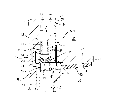
FIG. 3 illustrates a section across line I-I in
FIG. 6, showing a refrigerator in accordance with a
preferred embodiment of the present invention;
FIG. 4 illustrates a perspective disassembled
enlarged view of a cold air supply means in FIG. 3;
FIG. 5 illustrates a perspective enlarged view of
a cold air discharge guide in FIG. 3;
FIG. 6 illustrates a perspective disassembled
enlarged view of a cold air feed back means in FIG. 3;
FIG. 7 illustrates a partial section across line
II-II in FIG. 6, showing an assembled barrier in FIG. 3;
and,
FIG. 8 illustrates an overall cold air circulating
paths of a refrigerator in accordance with a preferred
embodiment of the present invention, schematically.
6b
CA 02290773 2000-02-15
DETAILED DESCRIPTION OF THE PREFERRED EMBODIMENT
Reference will now be made in detail to the preferred embodiments of the
present
invention, examples of which are illustrated in the accompanying drawings.
FIG. 3 illustrates a
section across line L-I in FIG. 6, showing a refrigerator in accordance with a
preferred
embodiment of the present invention, referring to which an overall structure
of the refrigerator
of the present invention will be explained.
There is cold air supply means 500 in front of an evaporator 44 for supplying
the cold air
heat exchanged in the evaporator 44 to a refrigerating chamber and a freezing
chamber. And,
there is a discharge guide 100 in rear of a barrier 70 for guiding the cold
air from the cold air
supply means 500 to the refrigerating chamber. There is cold air feed back
means 600 in a bottom
of the barrier 70 and in a rear wall of the refrigerator for feeding the cold
air circulated through
the refrigerating chamber. The cold air feed back means 600 includes a feed
back duct assembly
under the barrier 70, and a feed back guide 72 having one side in
communication with the feed
back duct assembly 60 and the other side in communication with a heat exchange
chamber 43 for
feeding the cold air in the refrigerating chamber to the heat exchange chamber
43.
Respective elements will be explained.
First, referring to FIGS. 3 and 4, the cold air supply means 500 will be
explained. The
cold air supply means 500 includes a grill pan 30 and a cover 32 fitted to a
back surface of the
grill pan 30 for supplying the cold air heat exchanged in the heat exchange
chamber 43 to the
freezing chamber and the refrigerating chamber, and feeding the cold air
circulated through the
freezing chamber back to the heat exchange chamber 43. A portion of a center
portion of the grill
pan 30 is projected forward(to the freezing chamber side) to form a projected
portion 30a, in rear
of which a cover 32 is provided so that a space 40 between the projected
portion 30a and the
7
CA 02290773 2000-02-15
cover 32 serves as a cold air passage for the cold air heat exchanged in the
evaporator 44. There
is an opening 32a in an upper portion of the cover 32 for supplying the cold
air heat exchanged
in the heat exchange chamber by means of a fan 42. There are cold air
discharge openings 34 for
the freezing chamber, i.e., an upper discharge opening 34a and a middle
discharge opening 34b
in an upper portion of the projected portion 30a in the grill pan 30, for
discharging the cold air
to the freezing chamber 20. And, there is a freezing chamber feed back opening
38 in a lower
portion of a portion 30b which is not projected for feeding the cold air
circulated through the
refrigerating chamber 20 back to a front surface of the evaporator. There is a
regulating plate 36
rotatably fitted in a lower portion of the cold air passage 40 for regulating
supply of the cold air
to the refrigerating chamber. If the regulating plate 36 closes the cold air
passage 40, cold air
supply to the refrigerating chamber 50 is cut off, to supply the cold air only
to the freezing
chamber 20. The regulating plate 36 may be in different forms, such as a
baffle of a damper.
The discharge guide 100 will be explained with reference to FIGS. 3 and S.
The discharge guide 100 is fitted in rear of the barrier 70. The discharge
guide 100 has
a refrigerating discharge passage 150 in communication with the cold air
passage 40 in the cold
air supply means 500. The cold air discharge guide 100 preferably has a
defrosted water drain
passage 20 for draining defrosted water from frost on the evaporator 44.
Accordingly, a portion
of cold air heat exchanged in the heat exchange chamber 43 is discharged to
the freezing chamber
through the cold air discharge opening 34 in the cold air supply means 500,
and the cold air
guided to downward is supplied to the refrigerating chamber duct 52 through
the refrigerating
discharge passage 150 and a refrigerating chamber supply opening 61 in the
feed back duct
assembly 60, which will be explained later.
Cold air feed back means 600 will be explained with reference to FIGS. 3 and
6.
8
CA 02290773 2000-02-15
The cold air feed back means 600 includes a feed back duct assembly 60 fitted
under the
barrier 70, and a feed back guide 72 substantially vertically fitted to one
end of the feed back duct
assembly 60 and buried in the rear wall of the refrigerator. There is a feed
back duct 62 on each
side of the feed back duct assembly 60 for guiding the cold air circulated
through the refrigerating
chamber 50 toward the evaporator 44, and there are a refrigerating chamber
supply opening 61
and a defrosted water collector 69 are formed at an approx. center in a rear
portion of the feed
back duct assembly 60 in communication with the refrigerating discharge
passage 150 in the
discharge guide 100 and the defrosted water passage 200, respectively. The
feed back duct 62
is one pair of projections 62a closely fitted to an under side of the barrier
70, to form cold air feed
back passages. And, there is a cold air opening 62a in a front portion(in a
direction of the door)
of the feed back duct 62 for receiving the cold air from the refrigerating
chamber. It is preferable
that a bottom surface of an end portion(a portion adjacent to the feed back
guide) of the feed back
duct 62 faces the defrosted water collector 69 with a downward slope for easy
collection of water
drops formed in the feed back passage 74 in the feed back guide connected to
the feed back duct
62. The feed back guide 72 in rear of the feed back duct assembly 62 guides
the cold air flowed
to the feed back duct assembly toward the evaporator 44. There are one pair of
feed back
passages 74 on opposite sides of the feed back guide 72, with a lower end
connected to one end
of the feed back duct 62 and an upper end in communication with a rear of the
heat exchanger
chamber 43. Therefore, the air circulated through the refrigerating chamber 50
is fed back to a
rear surface of the evaporator 44 through the feed back duct 62 and the feed
back passage 74,
such that the air is mostly brought into contact with the rear surface of the
evaporator 44 for heat
exchange. It is preferable that an outlet 74a of the feed back passage 74 is
sloped downwardly
for preventing reverse flow of the cold air. It is preferable that a front
portion and a middle
9
CA 02290773 2000-02-15
portion(between one pair of feed back ducts) of the feed back duct assembly
are cut away to form
cavities 65 and 67 for fitting various electric components which should be
fitted inside of the
refrigerator, such as refrigerating chamber lamp, door switch, timer, and etc.
The present invention facilitates formation of an insulating layer of
polyurethane having
excellent insulating performance and strength in the barrier 70 instead of the
Styrofoam in the
related art, because separate cold air circulating means 600, i.e., the feed
back guide, the feed
back assembly and the like can be used instead of forming the various ducts in
the barrier 70,
which serve as passages for feeding back the cold air in the barrier 70 to the
evaporator.
Cold air circulating paths in the refrigerator of the present invention will
be explained with
reference to FIGS. 3, 7 and 8.
Referring to FIG. 3, the cold air produced in the heat exchange chamber 43 is
supplied
to the cold air supply means S00 by the fan 42. A portion of the cold air
supplied to the cold air
supply means 500 is supplied to the freezing chamber 20 through the discharge
opening 34. And,
the other portion of the cold air flows downward along the cold air passage
40, and is supplied
to the refrigerating chamber 50 through the refrigerating discharge passage
150, the refrigerating
chamber supply opening 61, and the refrigerating chamber duct 52. The cold air
supply to the
refrigerating chamber 50 can be regulated by the regulating plate 36.
Different from the related
art, because the present invention has substantially straight cold air supply
paths, a flow resistance
can be minimized while cold air supply to the refrigerating chamber is made
smooth.
In the meantime, referring to FIGS. 7 and 8, the cold air relatively heated as
being heat
exchanged in the refrigerating chamber 50 flows into the feed back duct 62
through an inlet
portion 62a of the feed back duct assembly 60. The air flowed to the feed back
duct 62 is fed
back to the heat exchange chamber 43 through the feed back passage 74 in the
feed back guide
CA 02290773 2000-02-15
72. The cold air fed back to the heat exchange chamber 43 comes to contact
with the rear surface
of the evaporator 44. On the other hand, the cold air circulated through the
freezing chamber 20
is fed back to the heat exchange chamber 43 through the freezing chamber feed
back opening 38
in the grill pan 30. In this instance, the cold air fed back to the heat
exchange chamber 43 comes
to contact with the front surface of the evaporator 44. Thus, as the cold air
circulated through
the freezing chamber 20 and the refrigerating chamber SO respectively are
guided to the front
surface and the rear surface of the evaporator, to heat exchange in the front
and rear surfaces, a
heat exchange efficiency can be improved.
A process for draining defrosted water produced in the evaporator will be
explained.
A defrosting process is carried out periodically for removing frost grown on a
surface of
the evaporator 44 after a period of operation. The defrosting process is
removal of the frost on
the surface of the evaporator by putting a heater(not shown) on the evaporator
into operation.
The defrosted water produced in the defrosting process of the evaporator 44 is
collected in the
defrosted water collector 69 through the draining passage 200 in the discharge
guide 100. Since
the defrosted water collector 69 is formed at a rear end of the feed back duct
assembly 60, with
a slope, the defrosted water dropped from the feed back duct 74 in the feed
back guide 72 is
collected to the defrosted water collector 69, actually. The defrosted water
collected thus is
collected to a defrosted water container in a machinery room in a lower
portion of rear of the
refrigerator through the defrosted water drain opening 76 and a drain pipe 81,
and vaporized
therefrom.
The refrigerator of the present invention has the following advantages.
First, the stuffing inside of the barrier with an insulating layer of a
material having an
excellent insulating property, such as polyurethane, permits to form a thinner
barrier while the
11
CA 02290773 2000-02-15
barrier has an adequate insulating performance, that enlarges effective spaces
of the freezing
chamber and the refrigerating chamber. And, since the styrofoam can be
dispensed with, cost
saving and strengthening are possible. Especially, since formation of feed
back passages for the
freezing chamber and the refrigerating chamber in the barrier can be dispensed
with, the present
invention is favorable in view of strength. And, since the styrofoam can be
dispensed with, which
permits to omit sealing process, a refrigerator assembly process is
simplified.
Second, the feed back of the air circulated through the freezing chamber to
the front
surface of the evaporator and the air circulated through the refrigerating
chamber to the rear
surface of the evaporator, permitting heat exchange on the front and rear
surfaces of the
l0 evaporator, improves heat exchange efficiency. And, since such a feed back
system permits
formation of frost on all over the evaporator even, an air flow passing
through the evaporator is
uniform on the whole, which improves a heat exchange efficiency of the
evaporator, and cooling
performance of the refrigerator, and reduces power consumption.
Third, the almost straight cold air supply paths to the refrigerating chamber
can reduce
flow resistance, which further improves the refrigerating performance.
Finally, the defrosted water collector for collecting defrosted water provided
in the feed
back assembly in the cold air feed back means reduces a number of components
and permits an
assembly procedure simple.
And, the fitting of various components, such as door switches, a refrigerating
chamber
lamp, and etc., utilizing spaces other than the feed back ducts in the feed
back assembly is
favorable in view of convenience of overall inner space utilization and
maintenance.
It will be apparent to those skilled in the art that various modifications and
variations can
be made in the refrigerator of the present invention without departing from
the spirit or scope of
12
CA 02290773 2000-02-15
the invention. Thus, it is intended that the present invention cover the
modifications and
variations of this invention provided they come within the scope of the
appended claims and their
equivalents.
13