Note : Les descriptions sont présentées dans la langue officielle dans laquelle elles ont été soumises.
CA 02291397 1999-12-02
Atty. Docket No. 8501
LASHING SYSTEM
BACKGROUND OF THE INVENTION
The invention relates generally to lashing systems, and more particularly
to lashing systems having stretchable elastic cords and tackle therefor.
Lashing systems are known generally and use widely for fastening articles
to other members. It is known, for example, to fasten a net or an elastic cord
to
several fixed points on an outer portion of a backpack to form a web, which
may be
stretchable, between which articles are bundled or stowed. In the known prior
art
lashing systems, however, several points of the net or elastic cord are
permanently
fastened to the backpack so that the article capturing web formed thereby is
relatively
non-adjustably fixed thereon. The prior art lashing system thus imposes
generally
severe limitations on the number and size of articles stowable and on the
stowage
orientation thereof, due partly to the fixed web location and non-
adjustability thereof.
The present invention is drawn toward advancements in the art of lashing
systems and tackle therefor, useable for fastening articles to stationary
members.
An object of the invention is to provide novel lashing systems and tackle
therefor that overcome problems in the art, and that are economical.
A further object of the invention is to provide novel lashing systems and
tackle therefor that are relatively and easily adjustable, and that
accommodate a variety
of article shapes and sizes, and stowage orientations.
Yet another object of the invention is to provide novel lashing systems
and tackle therefor, and especially lashing systems having elastic cords
useable for
fastening articles to stationary members, including personal load carrying
packs,
luggage, seats, and vehicle beds, among other relatively stationary members.
A more particular object of the invention is to provide novel lashing
systems comprising generally at least one and preferably a plurality of cord
anchors
fastenable to a stationary member in spaced apart relation, and one or more
cord clips
1
CA 02291397 1999-12-02
"Lashing System" Atty. Docket No. 8501
each having a first portion with a first cord engaging member releasably
coupleable to
a first cord portion and a second portion with a second cord engaging member
conveniently and releasably coupleable to a second cord portion to accommodate
a
particular article stowage application. The cord anchors also have a cord
engaging
S member releasably coupleable to the cord, whereby the cord may be
selectively
coupled to one or more cord anchors, and thus positioned selectively on the
stationary
member. The lashing system also includes preferably a cord hook coupled to a
first
cord portion, the cord hook having a hook portion coupleable to another cord
portion
by hooking thereto.
These and other objects, aspects, features and advantages of the present
invention will become more fully apparent upon careful consideration of the
following
Detailed Description of the Invention and the accompanying Drawings, which may
be
disproportionate for ease of understanding, wherein like structure and steps
are
referenced generally by corresponding numerals and indicators.
BRIEF DESCRIPTION OF THE DRAWINGS
FIG. 1 is a lashing system according to an exemplary embodiment of the
invention.
FIG. 2 is a perspective the view of an exemplary cord anchor according
to the invention.
Zp FIG. 3 is a perspective view of an exemplary cord clip according to the
invention.
FIG. 4 is a perspective view of an exemplary cord hook according to the
invention.
FIG. S is a side view of the exemplary cord anchor.
FIG. 6 is a side view of the exemplary cord clip.
FIG. 7 is an end view of the exemplary cord hook.
2
CA 02291397 1999-12-02
"Lashing System" Atty. Docket No. 8501
DETAILED DESCRIPTION OF THE INVENTION
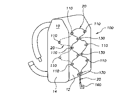
FIG. 1 illustrates a lashing system 100 useable for fastening articles to
a stationary member 10, which in the exemplary embodiment is a personal load
carrying pack, for example, a backpack, knapsack, waistpack, fanny-pack, or
other pack
mountable on a human or animal torso. The stationary member 10 may be embodied
more generally as luggage or as a hand bag. The stationary member 10 may also
be
embodied as a seat, for example the seat of a motorcycle or automobile or
watercraft,
or may be embodied as an automobile trunk space, or as a vehicle bed, for
example
the bed of a pick-up truck or non-motorized vehicle. Thus the term "stationary
member" as used in the present specification and the claims thereof is to be
interpreted broadly as being any one or more of the aforementioned
embodiments.
FIG. 1 illustrates the lashing system 100 comprising generally a cord 20
releasably fastenable to the stationary member 10, and preferably a
stretchable elastic
cord having a first axial diameter when the cord is unstretched and a second
axial
diameter smaller than the first diameter when the cord is stretched. The cord
may be
by itself as in FIG. 1, or may be a portion of an elastic or inelastic web, or
net, of the
same or dissimilar material. The cord may, for example, be woven or fed
through a
perimeter portion of a net, or may itself be woven or sewn or otherwise
fabricated to
form a net. In other embodiments, the cord is relatively inelastic and non-
stretchable.
The lashing system 100 also comprises generally at least one and
preferably a plurality of at least two cord anchors 110 fastenable to the
stationary
member 10, preferably in spaced apart relation where more than one cord anchor
is
employed. FIG. 1 illustrates a plurality of cord anchors 110 fastened to
corresponding
portions of the stationary member 10, and in the exemplary embodiment the cord
anchors are arranged in two generally spaced apart rows, or arrays, disposed
on a back
side portion 12 of the stationary member 10. One or more cord anchors 110 may
also
be disposed on other portions of the stationary member 10, for example on
portions
14 thereof, as illustrated in FIG. 1. This configuration of the cord anchors
110
3
CA 02291397 1999-12-02
"Lashing System" Atty. Docket No. 8501
however is only exemplary and is not intended to be limiting.
The configurations, and more particularly the location of fastening of the
plurality of cord anchors 110 on the stationary member are many, and depend to
some
extent on the type of stationary member to which the one or more cord anchors
are
S fastened. According to the invention, the plurality of cord anchors 110 are
located on
at least one and preferably many surface portions of the stationary member to
provide
many possible article stowing configurations for different articles as
discussed below.
According to one aspect of the invention, the cord 20 is fastened to the
stationary member 10 by the one or more cord anchors 110. More particularly,
the
cord is coupled, and preferably releasably coupleable, to the one or more cord
anchors
110 by corresponding cord engaging members thereof. In the exemplary
embodiment,
there are a plurality of cord anchors 110 fastened to the stationary member
10, and
the cord 20 may be selectively releasably coupled to any one or more of the
cord
anchors 110 to accommodate various stowable article sizes, shapes and numbers,
or to
stow an article in a particular location or orientation, depending on the
particular
requirements of the stowage application.
FIGS. 2 and 5 illustrate the cord anchor 110 having a body member 120
with a cord engaging member 112 on a cord engaging portion 122 thereof, to
which
the cord 20 is coupled, preferably releasably as discussed further below. The
cord
engaging member 112 of each of the plurality of cord anchors includes an
opening 114
through the cord anchor 110 for receiving the cord 20. The opening 114 of cord
anchor 110 has preferably an open end portion 116 to permit hooking engagement
of
the cord 20.
The opening 114 of the cord anchor 110 and the open end portion 116
thereof are sized to retain the cord 20, and to prevent separation of the cord
therefrom when the cord is disposed through the opening 114, thereby
preventing loss
of the cord 20.
In some applications, it is desirable for the cord 20 to be freely movable
axially through the opening 114 of the cord anchor 110, and thus a generally
bore
4
CA 02291397 1999-12-02
"Lashing System" Atty. Docket No. 8501
shaped diameter of the opening 114 is sized slightly larger than a diameter of
the cord
20 for this purpose. In other words, the cord 20 is freely movable in either
direction
through the opening 114 of the cord anchor 110. The open end portion 116 of
the
opening 114 is generally a gap having an opening width sized less than the
cord
diameter to ensure secure retention of the cord 20 in the opening 114, and
preferably
at the same time permit releasable coupling of the cord 20 to the cord anchor
110.
In other alternative applications, it is desirable to frictionally clamp the
cord 20 to prevent free axial movement of the cord through the opening 114 of
the
cord anchor 110. In this alternative application, the generally bore shaped
diameter
of the opening 114 is somewhat less than the cord diameter to generate some
friction
therebetween. The generally bore shaped diameter of the opening 114 is sized
relative
to the cord diameter to obtain a desired degree of friction therebetween, and
thus to
control the ease with which the cord 20 is movable relative to the cord anchor
110.
The open end portion 116 of the opening 114 is generally sized less than the
cord
diameter to ensure secure retention of the cord 20 in the opening 114, and
preferably
to permit releasable coupling of the cord to the cord anchor 110, as discussed
above.
In one embodiment, the cord anchor 110 is formed of acetal or
polyethylene or some other plastic or composite material in a molding
operation. The
cord anchor may be formed alternatively of a metal material in a stamping or
casting
operation, or some other material. Also, the cord anchor may be formed so that
it is
more or less resilient. The cord anchor may be a unitary member or an
assembly.
Where the cord anchor 110 is more resilient, the cord 20 may be inserted
through the open end portion 116 and into the opening 114 thereof by flexing
the
resilient cord anchor. In embodiments where the cord is a stretchable elastic
cord, the
cord diameter may be reduced by stretching thus allowing insertion of the cord
into
the opening 114, particularly in embodiments where the cord anchor is less
resilient.
In embodiments where the cord anchor is resilient and the cord is a
stretchable elastic,
stretching the cord or flexing the cord anchor or a combination thereof
facilitates
insertion of the cord into the opening of the cord anchor.
5
CA 02291397 1999-12-02
"Lashing System" Atty. Docket No. 8501
In one embodiment, the cord 20 is retained and preferably frictionally
clamped by the opening 114 of the cord anchor 110 to which the cord 20 is
fastened,
thereby axially fixing the cord 20 relative to the cord anchor 110. Where the
cord 20
is a stretchable elastic cord, the cord is fastened to the cord anchor 110 by
stretching
S and inserting the stretched cord through the open end portion 116 and into
the
opening 114, as discussed above, and the cord 20 is clamped in the opening 114
of the
cord anchor 110 upon unstretching the cord so that the diameter thereof is at
the first
relatively large diameter.
A stretchable cord 20 clamped by the cord anchor 110 is subsequently
movable axially through the opening 114 of the cord anchor by stretching the
cord to
reduce its diameter smaller than its unstretched diameter at least to an
extent that
permits axial movement of the cord through the opening 114, thereby permitting
precise positional adjustment of where the cord is fastened to the cord anchor
110.
The cord 20 whether stretchable or not may also be moved through the opening
114
of the cord anchor 110 by flexing the cord anchor in a manner that unclamps
the cord,
for example by tugging sufficiently on the cord, or where the cord is
stretchable by
stretching cord, or by a combination thereof.
The cord anchor 110 also comprises an anchoring portion 124 fastenable
to the stationary member. In FIGS. 2 and 5, the anchoring portion 124 includes
a
strap opening 125 therethrough for accommodating a fastening looped strap
portion,
not shown, but which may be sewn or riveted or otherwise fastened to the
stationary
member 10. Alternatively, the anchoring portion 124 may be a fabric portion
insert
molded in the cord engaging portion 122, whereby the fabric anchoring portion
124
itself is sewn or riveted directly to the stationary member 10. In other
alternative
2$ embodiments, a plastic anchoring portion 124 of a unitary plastic anchor
110 is sewn
or riveted directly to the stationary member 10.
FIG.1 illustrates the lashing system 100 further comprising generally one
or more cord clips 130 fastenable to the cord 20. FIGS. 3 and 6 illustrate the
cord clip
130 having a body member 140 with a first cord engaging member 132 on a first
6
CA 02291397 1999-12-02
"Lashing System" Atty. Docket No. 8501
portion 142 thereof and a second cord engaging member 134 on a second portion
thereof 144, to which portions of the cord 20 are coupled, preferably
releasably as
discussed further below. The first cord engaging member 132 of each of the
plurality
of cord clips 130 includes a first opening 133 through the cord clip for
receiving the
S cord 20. The first opening 133 of the cord clip 130 also has preferably a
first open end
portion 136 to permit hooking engagement of the cord 20.
The first opening 133 of the cord clip 130 and the first open end portion
136 thereof are sized to retain the cord 20, and to prevent separation of the
cord 20
therefrom when the cord is disposed through the first opening 133 thereof,
thereby
preventing loss of the cord 20.
In some applications, it is desirable for the cord 20 to be freely movable
axially through the first opening 133 of the cord clip 130, and thus a
generally bore
shaped diameter of the first opening 133 is sized slightly larger than a
diameter of the
cord 20 for this purpose. In other words, the cord clip 130 is freely movable
in either
direction along the cord 20. The first open end portion 136 of the first
opening 133
is generally a gap having a first opening width sized less than the cord
diameter to
ensure secure retention of the cord 20 in the first opening 133, and
preferably at the
same time to permit releasable coupling of the cord clip 130 to the cord 20.
Thus
configured, the first portion 142 of the cord clip 130 is securely fastenable
to the cord
20 so that the cord clip 130 is freely movable axially along the cord 20
without
substantial frictional engagement therebetween.
In other alternative applications, it is desirable to frictionally clamp the
cord 20 to prevent free movement of the cord clip 130 axially along the cord
20. In
this alternative application, the generally bore shaped diameter of the first
opening 133
is somewhat less than the cord diameter to generate friction therebetween, and
is sized
relative to the cord diameter to obtain a desired degree of friction and thus
to control
the ease with which the cord clip is movable relative to the cord. The first
open end
portion 136 of the first opening 133 is sized less than the cord diameter to
ensure
secure retention of the cord 20 in the first opening 133, and preferably to
permit
7
CA 02291397 1999-12-02
"Lashing System" Atty. Docket No. 8501
releasable coupling of the cord clip 130 to the cord 20 as discussed above.
Thus
configured, the first portion 142 of the cord clip 130 is securely fastenable
to the cord
20 and is fixed axially relative thereto upon assembly therewith.
The second cord engaging member 134 of each of the plurality of cord
clips 130 also includes a second opening 135 through the cord clip for
receiving the
cord 20. The second opening 135 of cord clip 130 also has preferably a second
open
end portion 137 to permit hooking engagement of the cord 20. The second
opening
135 of the cord clip 130 and the second open end portion thereof 137 are sized
preferably to retain the cord 20, and to prevent separation of the cord 20
therefrom
when the cord is disposed through the second opening 135 thereof. In other
embodiments the second open end portion 137 is not sized to retain the cord.
The second opening 135 of the cord clip 130 is sized preferably to permit
hooking engagement of the cord 20 without clamping the cord, so that the
second
portion 144 of the cord clip 130 may be moved axially along the cord 20
without
substantial frictional engagement therebetween, thereby permitting ready
fastening and
adjustment of the cord clip 130 to portions of the cord 20 to accommodate
various
article stowage objectives. In application, the second portion 144 of the one
or more
cord clips 130 may be selectively and removably fastened by hooking to the
cord 20 to
bundle or retain an article to the stationary member. Alternatively, the one
or more
cord clips 130 may be removably fastened by hooking to some other portion of
the
stationary member 10 besides the cord 20, for example to hooks or eyelets or
other
openings or other fastening points on the stationary member, thereby further
increasing the flexibility and range of application of the lashing system 100.
In one embodiment, the cord clip 130 is a unitary member formed of a
plastic, composite, metal or other material as discussed above in connection
with the
cord anchor 110. The cord clip 130 may also be formed so that it is more or
less
resilient. The cord clip 130 may be a unitary member or an assembly.
Where the cord clip 130 is more resilient, the cord 20 may be inserted
into the first and second openings 133 and 135 thereof by flexing the
resilient cord
8
CA 02291397 1999-12-02
"Lashing System" Atty. Docket No. 8501
clip. In embodiments where the cord is a stretchable elastic cord, the cord
diameter
may be reduced by stretching thus allowing insertion of the cord into the
first and
second openings of the cord clip, particularly in embodiments where the cord
clip is
less resilient. In embodiments where the cord clip is resilient and the cord
is a
stretchable elastic, stretching the cord or flexing the cord clip or a
combination thereof
facilitates insertion of the cord into the first and second openings of the
cord clip.
In embodiments where the cord clip 130 is retained and frictionally
clamped to an elastic stretchable cord 20 to axially fix the cord clip
thereto, the cord
clip may be fastened to the cord by stretching the cord and inserting the
stretched cord
into the first opening 133, via the second and first open end portions 137 and
135.
The cord 20 is then clamped in the first opening 133 of the cord clip 130 upon
unstretching the cord so that the diameter thereof is at the first relatively
large
diameter. The clamped cord is subsequently movable axially through the first
opening
133 of the cord clip by stretching the cord to reduce its diameter smaller
than its
unstretched diameter at least to an extent that permits axial movement of the
cord
therethrough. The cord 20 whether stretchable or not may also be moved through
the
first opening of the cord clip by flexing the cord clip in a manner that
unclamps the
cord, for example by tugging sufficiently on the cord, or where the cord is
stretchable
. by stretching cord, or by a combination thereof.
2p The lashing system 100 further comprises a cord hook 160 having a cord
end fastening portion 162 and a hook portion 164, and a portion of the cord
fastened
to the cord end fastening portion 162 thereof. Cord hooks are known generally
and
described more fully in U.S. Patent No. 4,368,999 issued 18 January 1983
entitled
"Coupling or Connecting End Part For Flexible Elements Such as Cables, Wires
or
Other Elements" assigned commonly herewith and incorporated herein by
reference.
FIG. 7 illustrates the cord fastening end portion 162 of the cord hook
160 having an opening 163 for accommodating one and preferably two free end
portions of the cord 20. Resilient arm portions 165 disposed on opposing side
portions
of the cord hook 160 are flexible at least partially into the opening 163, and
more
9
CA 02291397 1999-12-02
"Lashing System" Atty. Docket No. 8501
particularly corresponding cord engagement members 166 thereof bite into one
or
more cord end portions disposed into the cord opening 163 to retain the cord
portions
therein, thereby securely fastening the cord to the cord hook 160. FIG. 7
illustrates
one of the resilient arms 165 maintained in the flexed cord retaining position
by a clip
portion 167 snap-fit or otherwise fastened about the cord hook. Alternatively,
the one
or more end portions of the cord 20 may be insert molded in the cord hook 160.
The hook portion 164 of the cord hook 160 includes an opening 168
therethrough for receiving the cord 20, and the opening 168 preferably has an
open
end portion 169 to permit hooking engagement of the cord 20. The opening and
open
end portion thereof are preferably sized to permit hooking engagement, and in
some
embodiments releasable retention, of the cord without clamping thereof, as
discussed
generally above in connection with the cord anchor and cord clip, thereby
permitting
ready fastening and unfastening of the cord hook 160 to other portions of the
cord to
accommodate particular article stowage objectives and to securely stow the
cord and
, cord hook 160 when no articles are secured thereby. The cord hook 160 may
also be
fastened to portions of the stationary member, other than the cord 20, as
discussed
above in connection with the second cord engaging member 134 of the cord clip
130.
The lashing system 100 may also include a cord lock 170 disposed about
the cord 20, and more particularly about adjacent cord portions for fastening
or
drawing together the cord portions, thereby providing still further lashing
system 100
adjustability for accommodating and stowing articles. Cord locks are known
generally
and described more fully in U.S. Patent No. 5,197,166 issued 30 March 1993
entitled
"Cord Closure" assigned commonly herewith and incorporated herein by
reference.
While the foregoing written description of the invention enables one of
ordinary skill to make and use what is considered presently to be the best
mode
thereof, those of ordinary skill will understand and appreciate the existence
of
variations, combinations, and equivalents of the specific exemplary
embodiments
herein. The invention is therefore to be limited not by the exemplary
embodiments
herein, but by all embodiments within the scope and spirit of the appended
claims.