Sélection de la langue

Search

Sommaire du brevet 2291606 

Énoncé de désistement de responsabilité concernant l'information provenant de tiers

Une partie des informations de ce site Web a été fournie par des sources externes. Le gouvernement du Canada n'assume aucune responsabilité concernant la précision, l'actualité ou la fiabilité des informations fournies par les sources externes. Les utilisateurs qui désirent employer cette information devraient consulter directement la source des informations. Le contenu fourni par les sources externes n'est pas assujetti aux exigences sur les langues officielles, la protection des renseignements personnels et l'accessibilité.

Disponibilité de l'Abrégé et des Revendications

L'apparition de différences dans le texte et l'image des Revendications et de l'Abrégé dépend du moment auquel le document est publié. Les textes des Revendications et de l'Abrégé sont affichés :

  • lorsque la demande peut être examinée par le public;
  • lorsque le brevet est émis (délivrance).
(12) Brevet: (11) CA 2291606
(54) Titre français: BALAI D'ETANCHEITE A DOUBLE CONTACT
(54) Titre anglais: DUAL-CONTACT BRUSH SEAL
Statut: Périmé
Données bibliographiques
(51) Classification internationale des brevets (CIB):
  • F01D 11/08 (2006.01)
  • F02C 7/28 (2006.01)
  • F16J 15/54 (2006.01)
  • F16J 15/32 (2006.01)
(72) Inventeurs :
  • PLONA, DANIEL GEORGES (France)
  • THORE, MONIQUE ANDREE (France)
(73) Titulaires :
  • SNECMA (Non disponible)
(71) Demandeurs :
  • SOCIETE NATIONALE D'ETUDE ET DE CONSTRUCTION DE MOTEURS D'AVIATION "SNECMA" (France)
(74) Agent: LAVERY, DE BILLY, LLP
(74) Co-agent:
(45) Délivré: 2008-02-05
(22) Date de dépôt: 1999-12-01
(41) Mise à la disponibilité du public: 2000-06-10
Requête d'examen: 2004-10-22
Licence disponible: S.O.
(25) Langue des documents déposés: Anglais

Traité de coopération en matière de brevets (PCT): Non

(30) Données de priorité de la demande:
Numéro de la demande Pays / territoire Date
98 15572 France 1998-12-10

Abrégés

Abrégé français

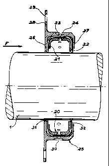
La présente invention concerne un balai d'étanchéité à double contact qui est facile à produire et à assembler. Il comprend essentiellement une seule bande souple de brins ou de fibres de brosse (30) qui sont contenus dans un corps constitué par une couronne intérieure (20) et une couronne extérieure (25). Les deux couronnes sont en forme de U de telle sorte qu'ils peuvent être utilisés pour positionner les deux extrémités (31, 32) de la bande souple (30) contre la surface extérieure de l'arbre rotatif (1). De préférence, les bras des deux couronnes (20 et 25) sont de longueurs différentes et se font face.


Abrégé anglais

The present invention relates to a dual-contact brush seal that is easy to produce and assemble. It mainly comprises a single flexible strip of strands or brush fibers (30) that is contained within a body constituted by an inner crown (20) and an outer crown (25). The two crowns are U-shaped such that they can be used to position the two ends (31, 32) of the flexible strip (30) against the outer surface of revolving shaft (1). Preferably, the arms of the two crowns (20 and 25) are of different lengths and face each other.

Revendications

Note : Les revendications sont présentées dans la langue officielle dans laquelle elles ont été soumises.


9


CLAIMS


1. Dual-contact brush seal to ensure leaktightness
between two chambers subjected to different pressures and
positioned around a shaft, the shaft being one of:
i) revolving and ii) fixed, comprising:
two flexible leaktight bundles parallel to each other,
an end of each bundle being in contact with an outer surface
of the shaft, said ends being separated from one another;
and
a support body in which the two flexible leaktight
bundles are fastened;
wherein the two flexible leaktight bundles are
constituted by a single, flexible, U-shaped strip, a central
section of said strip being fastened in the support body.

2. The dual-contact brush seal of claim 1, wherein
the support body comprises an inner crown and an outer
crown, each of said inner crown and said outer crown being
U-shaped and overlapping each other.

3. The dual-contact brush seal of claim 2, said inner
and outer crowns having arms of different lengths, the end
of each leaktight bundle being in contact with a single one
of said inner crown and outer crown.

4. The dual-contact brush seal of any one of claims 2
and 3, the seal being radial, wherein said seal comprises
polarizing means to ensure the inner crown and the outer
crown are assembled in a correct direction.

Description

Note : Les descriptions sont présentées dans la langue officielle dans laquelle elles ont été soumises.


CA 02291606 1999-12-01

2
DUAL-CONTACT BRUSH SEAL
DESCRIPTION
Field of the invention
The present invention relates to the leaktightness
between two chambers or volumes that are subjected to
different pressures and located around an axis or a
revolving shaft. The invention particularly relates to
aeronautical turbine engines that very often use the
type of leaktight seal called a brush seal.

Background art and the problem posed
Brush seals are bundles of wires, fibers or
strands that can be metal, organic or synthetic. The
material is chosen according to the environmental and
operational conditions of the brush seal, i.e.
according to the type of fluids to be kept leaktight,
the temperatures and pressures present on either side
of the seal.
Referring to figure 1, a joint of this type is
used to separate two volumes or two chambers A and B
that surround a revolving shaft 1. Preferably, the
bundle of wires 2 is positioned radially relative to
revolving shaft 1 and the end 2E of the bundle of wires
touches the outer surface of revolving shaft 1. The
bundle of wires 2 is fitted into a fixed support 3 that
constitutes the seal support. If we consider the
direction of air that flows through the seal and that
is indicated by arrow F, an upstream ring 5 is
preferably used that is located upstream of bundle of
wires 2 and that is positioned using a fastening ring
7, said fastening ring being fastened in seal support
3. A downstream ring 6 is also used, said ring being
SP 14636 JB


CA 02291606 1999-12-01

3
fastened downstream of bundle of wires 2 and positioned
to bear against a rib 4 of seal support 3. It should be
noted that the inner diameter of downstream ring 6 is
smaller than that of upstream ring 5. In other words,
the bundle of wires 2 is born over a greater distance
by the downstream ring than by upstream ring 5. End 2E
of bundle 2 has a certain degree of freedom,
particularly on the upstream end i.e. of the upstream
ring 5 The seal thus separates two zones in which
different pressures may be present.
Referring to figure 2, in French patent
application 2 607 893 discloses a brush seal that
comprises several bundles, and more particularly three
bundles in the example shown. The three bundles of
wires 12 are fastened perpendicularly to revolving
shaft 1 in relation to which they are used to separate
several zones, particularly upstream zone A and
downstream zone B that are positioned on either side of
the assembly of three bundles of wires 12. The bundles
of wires 12 are held by upstream ring 15 and downstream
ring 16 and are positioned relative to a seal support
13 using a rib 14 of said seal support.
The technical detail of all these types of brush
seals are well known. On the other hand, it is not
always easy to produce high quality brush seals.
Brush seals can also be positioned axially, for
example in semi-static applications or to equip a
slaved axial seal. In this event, it is impossible to
implement the standard techniques used in the design of
metal radial seals.
The aim of this invention is to propose a design
of axial brush seals with a double leaktight wall. This
design can also be applied to radial seals even though
they may be more complicated to assemble.

SP 14636 JB


CA 02291606 1999-12-01

4
Summary of the invention
In order to achieve this aim, the invention mainly
relates to an axial or radial dual-contact brush seal
to ensure leaktightness between two chambers subjected
to different pressures and positioned around a shaft
that is either revolving or fixed, comprising the
following:
- two flexible leaktight bundles that are parallel
to each other and each end of which is in contact with
the surface of the revolving or fixed shaft; and
- a support body in which the two flexible
leaktight bundles are fastened.
According to a main characteristic of the
invention the two flexible leaktight bundles are
constituted by a single, flexible, U-shaped strip the
central section of which is fastened in the support
body.
In the preferred embodiment the support body
comprises two crowns: an inner crown and an outer
crown, both of which are U-shaped and overlap each
other.
Preferably, the arms of the two U-shaped crowns
are not the same length such that the end of each
leaktight bundle is only in contact with a single
crown.
Preferably, in the event of a radial application,
polarizing means are used to ensure the two crowns are
assembled in the correct direction.
List of figures
The invention and its various technical
characteristics will be better understood from the
SP 14636 JB


CA 02291606 1999-12-01

following detailed description. The description refers
to the attached figures where:
- figure 1, described above, is a cross section of
a first type of brush seal of the prior art;
5 - figure 2, described above, is a cross section of
a second type of brush seal of the prior art;
- figure 3 is a cross section of a first radial
embodiment of the brush seal according to the
invention;
- figure 4 is a cross section of defective
assembly that should be avoided when the brush seal of
the invention is produced;
- figure 5 is a second radial embodiment of the
brush seal according to the invention; and
- figure 6 is a third axial embodiment of the
brush seal according to the invention.

Detailed description of two embodiments of the
invention
The brush seal of the invention will now be
considered, referring to figure 3, in a first radial
embodiment that is assembled around a revolving shaft
1. The brush seal comprises two main parts that are an
inner crown 20 and an outer crown 25. Besides the fact
that inner crown 20 and outer crown 25 are both
circular, in other words they surround revolving shaft
1, they both have U-shaped cross sections. Inner crown
20 is positioned inside outer crown 25. The two arms 21
and 22 of inner crown 20 are of different lengths, as
are the two arms 26 and 27 of outer crown 25.
Moreover, if arrow F is considered in an
aeronautical turbine engine upstream arm 26 of outer
crown 25 is longer than downstream arm 27 of said outer
crown. Contrarily, upstream arm 21 of inner crown 20 is
SP 14636 JB


CA 02291606 1999-12-01

6
shorter than downstream arm 22 of said inner crown. Due
to this each end 31 and 32 of flexible strip 30, that
constitutes the two leaktight bundles of the seal, is
only in contact with a single surface of a crown,
either inner crown 20 or outer crown 25. Therefore
upstream end 31 of flexible strip 30 is in contact with
upstream end 26 of outer crown 25 and downstream end 32
of flexible strip 30 is in contact with the outer
surface of downstream end 22 of inner crown 20. In this
embodiment both ends 31 and 32 of flexible strip 30
have a relatively high degree of freedom of movement,
particularly downstream. It should be noted that the
longest ends, i.e. upstream end 26 of the outer crown
and downstream end 22 of inner crown 20, are relatively
close to revolving shaft 1 in order to restrict the
freedom of movement of ends 31 and 32 in the upstream
section of the flexible strip. In other words, the long
sections or long arms 22 and 26 of inner crown 20 and
outer crown 25 are positioned facing each other to
guide the strands or the fibers that constitute the
brush of the flexible strip as close as possible to the
zone that is in contact with the surface of the
revolving shaft.
Outer crown 25 is fitted with an arm 28 which in
turn is provided with a fastening hole 29 intended to
fasten the seal in a turbine engine that is to be
fitted with the brush seal. Similarly, fastening means
are provided between inner crown 20 and outer crown 25
using fastening holes 23 and 24. Inner crown 20 and
outer crown 25 may also be fastened by welding,
riveting or by being slotted into the turbine engine.
Inner crown 20 and outer crown 25 should be fitted
with foolproofing means to assist the operator in
polarizing said crowns during assembly. When the crowns
SP 14636 JB


CA 02291606 1999-12-01

7
are assembled the arms of equal length of inner crown
20 and outer crown 25 could be located on the same side
of the seal if careless handling occurs, as shown in
figure 4 in which outer crown 25 is reversed compared
to the assembly in figure 3. In this event the brush
seal would clearly provide a lower performance level
from the first time it is used. Foolproofing means of
this kind could be constituted by a centering slug
fastened on one of the two crowns and a matching hole
provided in the other crown, these two components not
being located in the median plane between inner crown
and outer crown 25. To ensure the brush seal is
assembled in a certain direction, the central section
of inner crown 20 and outer crown 25 could also be
15 conical.
Referring to figure 5, a second radial embodiment
of the brush seal according to the invention is
assembled using a slightly different method. In this
example a support 40 is used that is concentric with
20 revolving shaft 1. The concentric support has an
upstream positioning rib 41 against which outer crown
is positioned. The downstream end of said outer
crown is fastened using an elastic ring 42 such that it
may be positioned axially relative to revolving shaft
25 1. Apart from this assembly characteristic, the
characteristics and constitution of the seal, i.e.
flexible strip 30, inner crown 20 and outer crown 25,
can be identical to those described in figure 3.
Figure 6 shows an axial-type seal according to the
invention. In this figure the seal is pressed against
the radial surface 11 of a revolving part, such as a
plate or the end surface of a wide shaft. The seal also
comprises a U-shaped flexible strip 53 that is held in
place by an inner crown 50 and an outer crown 55. These
SP 14636 JB


CA 02291606 1999-12-01

8
two crowns 50 and 55 have ends 56, 57, 61 and 62 of
different lengths in pairs for the same reasons as
those given for the radial seal. A fastening hole 59 is
provided in an arm 58 to fasten the seal.
The main advantages of the brush seal according to
the invention are that it may be radial, as described
in figures 4 and 5, but that it may also be axial as
described in figure 6.
Production and assembly of the brush seal are
clearly simplified, particularly for assembling the
inner and outer crowns for the axial-type seal.

SP 14636 JB

Dessin représentatif
Une figure unique qui représente un dessin illustrant l'invention.
États administratifs

Pour une meilleure compréhension de l'état de la demande ou brevet qui figure sur cette page, la rubrique Mise en garde , et les descriptions de Brevet , États administratifs , Taxes périodiques et Historique des paiements devraient être consultées.

États administratifs

Titre Date
Date de délivrance prévu 2008-02-05
(22) Dépôt 1999-12-01
(41) Mise à la disponibilité du public 2000-06-10
Requête d'examen 2004-10-22
(45) Délivré 2008-02-05
Expiré 2019-12-02

Historique d'abandonnement

Il n'y a pas d'historique d'abandonnement

Historique des paiements

Type de taxes Anniversaire Échéance Montant payé Date payée
Le dépôt d'une demande de brevet 300,00 $ 1999-12-01
Enregistrement de documents 100,00 $ 2000-01-17
Taxe de maintien en état - Demande - nouvelle loi 2 2001-12-03 100,00 $ 2001-11-19
Taxe de maintien en état - Demande - nouvelle loi 3 2002-12-02 100,00 $ 2002-11-19
Enregistrement de documents 50,00 $ 2003-09-16
Taxe de maintien en état - Demande - nouvelle loi 4 2003-12-01 100,00 $ 2003-11-25
Requête d'examen 800,00 $ 2004-10-22
Taxe de maintien en état - Demande - nouvelle loi 5 2004-12-01 200,00 $ 2004-11-23
Taxe de maintien en état - Demande - nouvelle loi 6 2005-12-01 200,00 $ 2005-11-24
Taxe de maintien en état - Demande - nouvelle loi 7 2006-12-01 200,00 $ 2006-11-22
Taxe finale 300,00 $ 2007-11-16
Taxe de maintien en état - Demande - nouvelle loi 8 2007-12-03 200,00 $ 2007-11-23
Enregistrement de documents 100,00 $ 2008-01-02
Taxe de maintien en état - brevet - nouvelle loi 9 2008-12-01 200,00 $ 2008-11-26
Taxe de maintien en état - brevet - nouvelle loi 10 2009-12-01 250,00 $ 2009-11-24
Taxe de maintien en état - brevet - nouvelle loi 11 2010-12-01 250,00 $ 2010-11-24
Taxe de maintien en état - brevet - nouvelle loi 12 2011-12-01 250,00 $ 2011-11-24
Taxe de maintien en état - brevet - nouvelle loi 13 2012-12-03 250,00 $ 2012-11-26
Taxe de maintien en état - brevet - nouvelle loi 14 2013-12-02 250,00 $ 2013-11-25
Taxe de maintien en état - brevet - nouvelle loi 15 2014-12-01 450,00 $ 2014-11-24
Taxe de maintien en état - brevet - nouvelle loi 16 2015-12-01 450,00 $ 2015-11-25
Taxe de maintien en état - brevet - nouvelle loi 17 2016-12-01 450,00 $ 2016-11-22
Taxe de maintien en état - brevet - nouvelle loi 18 2017-12-01 450,00 $ 2017-11-20
Taxe de maintien en état - brevet - nouvelle loi 19 2018-12-03 450,00 $ 2018-11-23
Titulaires au dossier

Les titulaires actuels et antérieures au dossier sont affichés en ordre alphabétique.

Titulaires actuels au dossier
SNECMA
Titulaires antérieures au dossier
LEXVALL
PLONA, DANIEL GEORGES
SNECMA MOTEURS
SOCIETE NATIONALE D'ETUDE ET DE CONSTRUCTION DE MOTEURS D'AVIATION "SNECMA"
THORE, MONIQUE ANDREE
Les propriétaires antérieurs qui ne figurent pas dans la liste des « Propriétaires au dossier » apparaîtront dans d'autres documents au dossier.
Documents

Pour visionner les fichiers sélectionnés, entrer le code reCAPTCHA :


Pour visualiser une image, cliquer sur un lien dans la colonne description du document. Pour télécharger l'image (les images), cliquer l'une ou plusieurs cases à cocher dans la première colonne et ensuite cliquer sur le bouton "Télécharger sélection en format PDF (archive Zip)" ou le bouton "Télécharger sélection (en un fichier PDF fusionné)".

Liste des documents de brevet publiés et non publiés sur la BDBC .

Si vous avez des difficultés à accéder au contenu, veuillez communiquer avec le Centre de services à la clientèle au 1-866-997-1936, ou envoyer un courriel au Centre de service à la clientèle de l'OPIC.


Description du
Document 
Date
(yyyy-mm-dd) 
Nombre de pages   Taille de l'image (Ko) 
Dessins représentatifs 2000-06-06 1 7
Abrégé 1999-12-01 1 19
Description 1999-12-01 7 283
Revendications 1999-12-01 1 36
Dessins 1999-12-01 4 68
Page couverture 2000-06-06 1 34
Dessins 2007-03-01 4 66
Revendications 2007-03-01 1 34
Abrégé 2007-03-01 1 15
Dessins représentatifs 2008-01-15 1 8
Page couverture 2008-01-15 1 35
Correspondance 2000-01-07 1 2
Cession 1999-12-01 3 101
Cession 2000-01-17 2 61
Taxes 2002-11-19 1 38
Taxes 2003-11-25 1 36
Cession 2003-09-16 51 2 439
Taxes 2001-11-19 1 39
Poursuite-Amendment 2004-10-22 1 22
Taxes 2004-11-23 1 33
Poursuite-Amendment 2005-08-30 1 30
Taxes 2005-11-24 1 52
Poursuite-Amendment 2006-09-06 2 72
Taxes 2006-11-22 1 44
Poursuite-Amendment 2007-03-01 7 150
Correspondance 2007-11-16 1 30
Taxes 2007-11-23 1 43
Cession 2008-01-02 10 666