Sélection de la langue

Search

Sommaire du brevet 2291841 

Énoncé de désistement de responsabilité concernant l'information provenant de tiers

Une partie des informations de ce site Web a été fournie par des sources externes. Le gouvernement du Canada n'assume aucune responsabilité concernant la précision, l'actualité ou la fiabilité des informations fournies par les sources externes. Les utilisateurs qui désirent employer cette information devraient consulter directement la source des informations. Le contenu fourni par les sources externes n'est pas assujetti aux exigences sur les langues officielles, la protection des renseignements personnels et l'accessibilité.

Disponibilité de l'Abrégé et des Revendications

L'apparition de différences dans le texte et l'image des Revendications et de l'Abrégé dépend du moment auquel le document est publié. Les textes des Revendications et de l'Abrégé sont affichés :

  • lorsque la demande peut être examinée par le public;
  • lorsque le brevet est émis (délivrance).
(12) Brevet: (11) CA 2291841
(54) Titre français: PROCEDE POUR LIQUEFIER UN ECOULEMENT RICHE EN HYDROCARBURES
(54) Titre anglais: METHOD FOR LIQUEFYING A FLOW RICH IN HYDROCARBONS
Statut: Périmé et au-delà du délai pour l’annulation
Données bibliographiques
(51) Classification internationale des brevets (CIB):
  • F25J 1/02 (2006.01)
  • C09K 5/04 (2006.01)
  • F25B 9/00 (2006.01)
  • F25J 3/06 (2006.01)
(72) Inventeurs :
  • STOCKMANN, RUDOLF (Allemagne)
  • BOLT, MANFRED (Allemagne)
  • STEINBAUER, MANFRED (Allemagne)
  • PFEIFFER, CHRISTIAN (Allemagne)
  • PAUROLA, PENTTI (Allemagne)
  • FORG, WOLFGANG (Allemagne)
  • FREDHEIM, ARNE OLAV (Norvège)
  • SORENSEN, OYSTEIN (Norvège)
(73) Titulaires :
  • LINDE AKTIENGESELLSCHAFT
  • DEN NORSKE STATS OLJESELSKAP A.S.
(71) Demandeurs :
  • LINDE AKTIENGESELLSCHAFT (Allemagne)
  • DEN NORSKE STATS OLJESELSKAP A.S. (Norvège)
(74) Agent: ERNEST PETER JOHNSONJOHNSON, ERNEST PETER
(74) Co-agent: PARLEE MCLAWS LLP
(45) Délivré: 2007-09-04
(86) Date de dépôt PCT: 1998-05-27
(87) Mise à la disponibilité du public: 1998-12-03
Requête d'examen: 2003-05-26
Licence disponible: S.O.
Cédé au domaine public: S.O.
(25) Langue des documents déposés: Anglais

Traité de coopération en matière de brevets (PCT): Oui
(86) Numéro de la demande PCT: PCT/EP1998/003128
(87) Numéro de publication internationale PCT: WO 1998054524
(85) Entrée nationale: 1999-11-26

(30) Données de priorité de la demande:
Numéro de la demande Pays / territoire Date
197 22 490.3 (Allemagne) 1997-05-28

Abrégés

Abrégé français

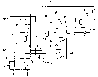
L'invention concerne un procédé pour liquéfier un écoulement riche en hydrocarbures, notamment un écoulement de gaz naturel, par échange de chaleur indirect avec le mélange de caloporteur d'un circuit de mélange de caloporteur, ledit mélange étant comprimé en au moins deux étapes et séparé en au moins une fraction à bas point d'ébullition et au moins une fraction à haut point d'ébullition. Selon l'invention, ledit mélange de caloporteur comprimé (23) est partiellement condensé (E4) au moins après l'avant-dernier étage de compresseur et séparé (D4) en une fraction liquide à haut point d'ébullition (26) et une fraction gazeuse à bas point d'ébullition (24). Cette dernière fraction (24) est comprimée à la pression finale, partiellement condensée (E5) et séparée (D5) en une fraction gazeuse à bas point d'ébullition (10) et une fraction liquide à haut point d'ébullition (27). Cette dernière (27) est mélangée à l'écoulement de mélange de caloporteur (23) partiellement condensé, et la fraction gazeuse (10) forme la fraction de mélange de caloporteur à bas point d'ébullition, et la fraction liquide (26) forme la fraction de mélange de caloporteur à haut point d'ébullition du circuit de mélange de caloporteur. En variante, le mélange de caloporteur comprimé (20, 31, 34) peut être condensé partiellement (E3, E4, E5) après chaque étage de compresseur, et séparé (D3, D4, D5) en une fraction gazeuse à bas point d'ébullition (21, 32, 10) et une fraction liquide à haut point d'ébullition (30, 33, 35). Seule la fraction gazeuse (21, 32) provenant de la condensation partielle (E3, E4) continue d'être comprimée, et les fractions liquides (33, 35) à partir de la deuxième séparation (D4, D5) sont mélangées à l'écoulement partiellement condensé (20) provenant du premier étage de compresseur avant leur séparation (D3). La fraction gazeuse (10) provenant de la dernière séparation (D5) forme alors la fraction de mélange de caloporteur à bas point d'ébullition, et la fraction liquide (30) provenant de la première séparation (D3) forme la fraction de mélange de caloporteur à haut point d'ébullition du circuit de mélange de caloporteur.


Abrégé anglais


The invention relates to a process for
liquefying a hydrocarbon-rich stream, in particular a
natural gas stream, by indirect heat exchange with the
refrigerant mixture of a refrigerant mixture cycle, the
refrigerant mixture being compressed in two stages or
multiple stages and where the refrigerant mixture is
fractionated into at least one lower-boiling
refrigerant mixture fraction and into at least one
higher-boiling refrigerant mixture fraction.
According to the invention, the compressed refrigerant
mixture (23) is at least partially condensed (E4)
downstream of the penultimate compressor stage and is
fractionated (D4) into a higher-boiling liquid fraction
(26) and a lower-boiling gas fraction (24). The
lower--boiling gas fraction (24) is compressed to the final
pressure, partially condensed (E5) and fractionated
(D5) into a lower-boiling gas fraction (10) and a
higher-boiling liquid fraction (27). The higher-boiling
liquid fraction (27) is added to the partially
condensed refrigerant mixture stream (23), and the gas
fraction (10) forms the lower-boiling refrigerant
mixture fraction and the liquid fraction (26) forms the
higher-boiling refrigerant mixture fraction of the
refrigerant mixture cycle. Alternatively to this, the
compressed refrigerant mixture (20, 31, 34) can be
partially condensed (E3, E4, E5) after each compressor
stage and fractionated in each case into a
lower--boiling gas fraction (21, 32, 10) and a higher-boiling
liquid fraction (30, 33, 35). Only the gas fraction
(21, 32) from the partial condensation (E3, E4) in each
case is further compressed and the liquid fractions 33,
35) from the second fractionation (D4, D5) on are added
to the partially condensed stream (20) from the first
compressor stage upstream of its fractionation (D3).

-2-
Again, the gas fraction (10) from the final
fractionation (D5) forms the lower-boiling refrigerant
mixture fraction and the liquid fraction (30) from the
first fractionation (D3) forms the higher-boiling
refrigerant mixture fraction of the refrigerant mixture
cycle.

Revendications

Note : Les revendications sont présentées dans la langue officielle dans laquelle elles ont été soumises.


11
CLAIMS:
1. Process for liquefying a hydrocarbon-rich stream, in particular a
natural gas stream, by indirect heat exchange with the refrigerant mixture of
a
refrigerant mixture cycle, the refrigerant mixture being compressed in two
stages or
multiple stages and where the refrigerant mixture is fractionated into at
least one
lower-boiling refrigerant mixture fraction and into at least one higher-
boiling
refrigerant mixture fraction, characterized in that
a) the compressed refrigerant mixture (23) is at least partially condensed
(E4) downstream of the penultimate compressor stage,
b) is fractionated (D4) into a higher-boiling liquid fraction (26) and a
lower-boiling gas fraction (24),
c) the lower-boiling gas fraction (24) is compressed to the final pressure,
d) the compressed lower-boiling gas fraction is partially condensed (E5),
e) is fractionated (D5) into a lower-boiling gas fraction (10) and a higher-
boiling liquid fraction (27),
f) the higher-boiling liquid fraction (27) is added to the partially
condensed refrigerant mixture stream (23), and
g) the gas fraction (10) forms the lower-boiling refrigerant mixture
fraction and the liquid fraction (26) forms the higher-boiling
refrigerant mixture fraction of the refrigerant mixture cycle.
2. Process for liquefying a hydrocarbon rich stream according to Claim 1,
characterized in that the higher-boiling liquid fraction (27) is expanded (f)
upstream
of the addition to the partially condensed refrigerant mixture stream (23).

12
3. Process for liquefying a hydrocarbon-rich stream, in particular a
natural gas stream, by indirect heat exchange with the refrigerant mixture of
a
refrigerant mixture cycle, the refrigerant mixture being compressed in two
stages or
multiple stages and where the refrigerant mixture is fractionated into at
least one
lower-boiling refrigerant mixture fraction and into at least one higher-
boiling
refrigerant mixture fraction, characterized in that
a) the compressed refrigerant mixture (20, 31, 34) is partially condensed
(E3, E4, E5) downstream of each compressor stage and is fractionated
(D3, D4, D5) each time into a lower-boiling gas fraction (21, 32, 10)
and a higher-boiling liquid fraction (30, 33, 35),
b) only the gas fraction (21, 32) from each partial condensation (E3, E4)
is further compressed,
c) the liquid fractions (33, 35), from the second fractionation (D4, D5)
on, are added to the partially condensed stream (20) from the first
compressor stage prior to its fractionation (D3) and
d) the gas fraction (10) from the last fractionation (D5) forms the lower-
boiling refrigerant mixture fraction and the liquid fraction (30) from
the first fractionation (D3) forms the higher-boiling refrigerant mixture
fraction of the refrigerant mixture cycle.
4. Process for liquefying a hydrocarbon-rich stream according to Claim 3,
characterized in that the liquid fraction (33, 35) produced by means of the
fractionation (D4, D5) is fed in each case to the preceding pressure stage
stream
which is to be fractionated (20, 31) upstream of its fractionation (D3, D4).
5. Process for liquefying a hydrocarbon-rich stream according to Claim 3
or 4, characterized in that the liquid fraction (33, 35) produced by means of
the
fractionation (D4, D5) is expanded (f, g) upstream of the feed to the
preceding
pressure stage stream (20, 31) which is to be fractionated.

13
6. Process for liquefying a hydrocarbon-rich stream according to one of
the preceding claims, characterized in that the lower-boiling refrigerant
mixture
fraction (10) essentially consists of
from 5 to 20 mol% of N2,
from 30 to 55 mol% of CH4,
from 30 to 55 mol% of C2H6 or C2H4,
from 0 to 10 mol% of C3H8 or C3H6 and
from 0 to 10 mol% of iC4H10 of nC4H10,
the higher-boiling refrigerant mixture fraction (26, 30) of the refrigerant
mixture cycle
consists of
from 0 to 5 mol% of N2,
from 0 to 15 mol% of CH4,
from 25 to 55 mol% of C2H6 or C2H4,
from 0 to 20 mol% of C3H8 or C3H6,
from 30 to 60 mol% of iC4H10 or nC4H10 and
from 0 to 5 mol% of C5H12.
7. Process for liquefying a hydrocarbon-rich stream according to claims
1, 2, 3, 4, 5 or 6, characterized in that the series-connected compressors
used for the
compression of the refrigerant mixture are driven by only one drive apparatus,
in
particular a gas turbine.
8. Process for liquefying a hydrocarbon-rich stream according to claims
1, 2, 3, 4, 5, 6 or 7, characterized in that, in the case of a plant or
process downtime,
the lower-boiling refrigerant mixture fraction and the higher-boiling
refrigerant
mixture fraction are stored temporarily in at least two separate
separators/storage
vessels (D3, D4, D5).

Description

Note : Les descriptions sont présentées dans la langue officielle dans laquelle elles ont été soumises.


CA 02291841 2006-10-03
1
Description
Method For Liquefying a Flow Rich in Hydrocarbons
The invention relates to a process for liquefying a
hydrocarbon-rich stream, in particular a natural gas stream,
by indirect heat exchange with the refrigerant mixture of a
refrigerant mixture cycle, the refrigerant mixture being
compressed in two stages or multiple stages and where the
refrigerant mixture is fractionated into at least one lower-
boiling refrigerant mixture fraction and into at least one
higher-boiling refrigerant mixture fraction.
Currently, most of the baseload-LNG plants are designed
as what are termed dual-flow refrigeration processes. In
these, the refrigeration energy required for liquefying the
hydrocarbon-rich stream or the natural gas is provided by two
separate refrigerant mixture cycles which are connected to a
refrigerant mixture cycle cascade. A liquefaction process of
this type is disclosed, for example, by GB-B 895 094.
In addition, liquefaction processes are known in which
the refrigeration energy required for the liquefaction is
provided by a refrigerant cycle cascade, but not a refrigerant
mixture cycle cascade, see, for example, LINDE Berichte aus
Technik und Wissenschaft, issue 75/1997, pages 3 - 8. The
refrigerant cycle cascade described therein consists of a
propane or propylene, an ethane or ethylene and a methane
refrigeration cycle. Although this refrigerant cycle cascade
can be considered to be optimized energetically, it is
relatively complicated owing to the nine compressor stages.
In addition, liquefaction processes are known, for
example as described in DE-B 19 60 301, in which the
refrigeration energy required for the liquefaction is provided
by a cascade consisting of a refrigerant mixture cycle and a
propane pre-cooling cycle.
{E5226348. DOC;1 }

CA 02291841 1999-11-26
H 97/073 = H 2206
27.05.97 - Zahn/fi - 2 -
Alternatively to the refrigerant or refrigerant
mixture cycle cascades mentioned, the refrigeration
energy required for the liquefaction can also be
provided by only one refrigerant mixture cycle. These
what are termed single-flow proce'.bses generally require
a lower number of -apparatuses and machines, compared
with the abovementioned cascades, for which reason the
capital expenditure costs are lower compared with
processes having a plurality of refrigerant (mixture)
cycles. In addition, the operation of such single-flow
processes is comparatively simple. However, it is a
disadvantage that the specific energy requirement for
liquefaction is higher compared with processes having a
plurality of refrigerant (mixture) cycles.
US-A 5,535,594 discloses such a single-flow
process in which the refrigerant mixture cycle stream
is dissolved into two separate refrigerant mixture
cycle streams, a higher-boiling refrigerant mixture
fraction and a lower-boiling refrigerant mixture
fraction, by means of a distillation column which is
disposed between the penultimate and final compressor
stage of the refrigerant compressor, and by means of a
reflux separator which is disposed downstream of the
last stage of the refrigerant compressor.
The higher-boiling refrigerant mixture
fraction, that is the bottom product of the
distillation column, is used for precooling the
hydrocarbon-rich stream to be liquefied and the lower-
boiling refrigerant fraction and for cooling against
itself. The lower-boiling refrigerant mixture fraction,
that is the overhead product of the reflux separator,
is, after it has been precooled by the higher-boiling
refrigerant mixture fraction, used for the liquefaction
and subcooling of the hydrocarbon-rich stream to be
liquefied and for cooling against itself.
The object of the present invention is to
specify a process for liquefying a hydrocarbon-rich
stream, in particular a natural gas stream, by means of

CA 02291841 2006-02-17
-3-
what is termed a single-flow process, in which the specific
energy requirement of the single-flow process is improved with
retention of its advantages - low capital costs and simple and
robust operation.
This is achieved according to the invention by means of
the fact that
(a) the compressed refrigerant mixture is at least partially
condensed downstream of the penultimate compressor stage,
(b) is fractionated into a first higher-boiling liquid
fraction and a first lower-boiling gas fraction,
(c) the first lower-boiling gas fraction is passed directly
to the final compressor stage and compressed to the final
pressure,
(d) the compressed first lower-boiling gas fraction is
partially condensed,
(e) is fractionated into a second lower-boiling gas fraction
and a second higher-boiling liquid fraction,
(f) the second higher-boiling liquid fraction is added to the
partially condensed refrigerant mixture stream, prior to
being fractionated in step (b), and
(g) the second lower boiling gas fraction forms the lower-
boiling refrigerant mixture fraction and the liquid
fraction forms the higher-boiling refrigerant mixture
fraction of the refrigerant mixture cycle.
In a development of the process according to the
invention it is proposed that the higher-boiling liquid
fraction is expanded upstream of the addition to the partially
condensed refrigerant mixture stream.
An alternative procedure to this described procedure of the
invention is characterized in that
(a) the compressed refrigerant mixture is partially condensed
downstream of each compressor stage and is fractionated each
time into a lower-boiling gas fraction and a higher-boiling
liquid fraction,
{ E5146839.DOC; l }

CA 02291841 1999-11-26
H 97/073 = H 2206
27.05.97 - Zahn/fi - 4 -
b) only the gas fraction from each partial
condensation is further compressed,
c) the liquid fractions, from the second
fractionation on, are added to the partially
condensed stream from the first compressor stage
prior to its'f"ractionation and
d) the gas fraction from the last fractionation forms
the lower-boiling refrigerant mixture fraction and
the liquid fraction from the first fractionation
forms the higher-boiling refrigerant mixture
fraction of the refrigerant mixture cycle.
According to an advantageous embodiment of the
process of the invention, the liquid fraction produced
by means of the fractionation is fed in each case to
the preceding pressure stage stream which is to be
fractionated upstream of its fractionation.
As a development of the process of the
invention it is proposed that the liquid fraction
produced by means of the fractionation is expanded
upstream of the feed to the. preceding pressure stage
stream which is to be fractionated.
The process of the invention and other
embodiments of the same are to be described in more
r.~ detail with reference to Figures 1 and 2.
Possibly necessary pretreatment steps of the
hydrocarbon-rich stream prior to the liquefaction, for
example removal of acid gas and/or mercury, removal of
heavy hydrocarbons etc., which are not subject matter
of the present invention are not considered in more
detail below.
The hydrocarbon-rich stream to be liquefied is
fed via line 1 to a heat exchanger El and precooled in
this against the refrigerant mixture (cycle) stream
which is to be heated. The precooled hydrocarbon-rich
stream is then fed via line 2 to the heat exchanger E2
and is liquefied and subcooled in this against the two

CA 02291841 1999-11-26
H 97/073 = H 2206
27.05.97 - Zahn/fi - 5 -
partial streams of the refrigerant mixture cycle which
will be considered in more detail below.
The liquefied and subcooled hydrocarbon-rich
stream which is taken off from the heat exchanger E2
via line 3 is either expanded irit the liquid expansion
turbine Ti or, alternatively to this, in an expansion
valve a which is provided in the bypass line 4. Then,
the liquefied and subcooled hydrocarbon-rich stream is
fed to a further processing stage, for example a
nitrogen-separation stage, and/or is expanded via the
valve b and line 5 into a storage vessel operating at
approximately atmospheric pressure. The valve b serves
for maintaining pressure, which prevents vaporization
of the liquefied and subcooled stream at the outlet of
the liquid expansion turbine T1.
The refrigerant mixture stream taken off from
the heat exchanger El via line 18 is fed to a suction
vessel D2 which serves to protect the first compressor
stage. From this suction vessel the refrigerant mixture
stream which is to be compressed is fed via line 19 to
the first stage of the compressor V. The compressor V
has two or more, three in the case of Figures 1 and 2,
compressor stages; these are shown by the two dash-
dotted lines.
A condensate which may arise downstream of the
first compressor stage of the compressor V is fed via
line 20 to a separator D3. In this line 20 is provided
a cooler E3. The gas fraction arising at the top of the
separator D3 is fed via line 21 to the suction side of
the second compressor stage of the compressor V. The
liquid fraction taken off from the separator D3 is
pumped by means of the pump Pi to the final pressure of
the second compressor stage of the compressor V and
added via line 22 to the outlet stream of this second
compressor stage in line 23.
The compressed refrigerant mixture stream in
line 23 is partially condensed in a further cooler E4
and fed to the separator D4. The cooling or

CA 02291841 1999-11-26
H 97/073 = H 2206
27.05.97 - Zahn/fi - 6 -
condensation of the respective streams from the
individual compressor stages in the heat exchangers or
coolers E3, E4 and E5 can be effected with seawater or
cooling water, air or any other suitable cooling
medium.
The gas fraction arising at the top of the
sseparator D4 is fed via line 24 to the final
compressor stage of the compressor V. The higher-
boiling liquid fraction from the separator D4 is fed
via line 26 to the heat exchanger El; this liquid
fraction will be considered in more detail below.
The refrigerant stream compressed in the final
compressor stage of the compressor V is cooled and
partially condensed in the heat exchanger E5. Then, the
refrigerant mixture stream is fed via line 25 to the
separator D5. At the top of this separator D5 a lower-
boiling gas fraction is taken off via line 10 and fed
to the heat exchanger El. At the bottom of the
separator D5 a higher-boiling liquid fraction is taken
off via line 27, expanded in valve f to the final
pressure of the second compressor stage and added to
the already partially condensed refrigerant mixture in
line 23.
The gas fraction taken off at the top of the
separator D5 via line 10 forms the lower-boiling
refrigerant mixture fraction of the refrigerant mixture
cycle, while the liquid fraction taken off from the
separator D4 via line 26 forms the higher-boiling
refrigerant mixture fraction of the refrigerant mixture
cycle.
The lower-boiling refrigerant mixture fraction
and the higher-boiling refrigerant mixture fraction are
fed via lines 10 and 26, as mentioned above, to the
heat exchanger El. The lower-boiling refrigerant
mixture fraction precooled in heat exchanger El is fed
via line 11 to the separator Dl. At the top of this
separator Dl a gaseous fraction is taken off via line
12 and fed to the heat exchanger E2, liquefied and

CA 02291841 1999-11-26
H 97/073 = H 2206
27.05.97 - Zahn/fi - 7 -
subcooled in this and then expanded in valve c. This
fraction is then fed back via line 14 to the heat
exchanger E2 and vaporized against the hydrocarbon-rich
stream which is to be condensed and subcooled as well
as against itself.
From the= bottom of separator Dl, a liquid
fraction is taken off via line 13 and fed to the heat
exchanger E2, subcooled in this and then fed via line
to a liquid expansion turbine T2 and expanded in
10 this. Alternatively to this, .this subcooled fraction
can also be expanded in a valve, which is not shown in
the figure, which is disposed in parallel to the liquid
expansion turbine T2. Via line 16, in which a valve d
is provided, the expanded fraction is added to the
15 heated stream in line 14. The valve d in turn serves
for maintaining pressure, which prevents vaporizing of
the liquid at the outlet of the liquid expansion
turbine T2.
The mixed stream is further vaporized and
heated in heat exchanger E2 against the hydrocarbon-
rich stream which is to be liquefied and against the
liquid fraction and the gas fraction of the separator
Dl in lines 13 and 12, respectively. Then, this stream
is fed via line 17 to the heat exchanger El and heated
in this against the hydrocarbon-rich stream which is to
be precooled and against the lower-boiling refrigerant
mixture fraction which is to be precooled and the
higher-boiling refrigerant mixture fraction which is to
be precooled. Thereupon, this refrigerant mixture
stream is fed, as described above, via line 18 to the
suction vessel D2.
The higher-boiling refrigerant mixture fraction
fed to the heat exchanger El via line 26 is cooled in
heat exchanger El and then expanded in valve e. The
expanded higher-boiling refrigerant mixture fraction is
then added to the lower-boiling refrigerant fraction in
line 17.

CA 02291841 1999-11-26
H 97/073 = H 2206
27.05.97 - Zahn/fi - 8 -
By resolving the refrigerant mixture stream of
the single-flow process into a lower-boiling
' refrigerant mixture fraction and a higher-boiling
refrigerant mixture fraction, the specific energy
consumption of the process is iml5roved. Since for this
fractionation only two separators are used, that is to
say separators D4 and D5, the increase in apparatus
required for the fractionation is low. The two said
separators can serve here simultaneously as collection
vessels for the refrigerant mixture or the two
refrigerant mixture fractions. They thus replace a
collection vessel which would also have to be provided
in a single-flow process without resolution of the
refrigerant mixture.
As mentioned above, the compressor outlet
streams are cooled in the coolers or heat exchangers
E3, E4 and E5 by means of suitable coolants, such as
seawater or cooling water, air etc. In order to
increase the efficiency of the fractionation into a
lower-boiling refrigerant mixture fraction and a
higher-boiling refrigerant mixture fraction, in the
case of high coolant temperatures, the refrigerant
mixture stream is further cooled downstream of the
penultimate compressor stage, in addition to the
cooling in heat exchanger E4, in another heat
exchanger, using a chilled water unit or in heat
exchanger El for example, and only then fed to the
separator D4.
A process procedure alternative to the process
procedure shown in Figure 1 is shown in Figure 2.
Below, only the differences between the process
procedures of Figures 1 and 2 will be considered.
In the case of the mode of operation according
to Figure 2, the higher-boiling refrigerant mixture
fraction is not formed from the liquid taken off at the
bottom of the separator D4 but from the liquid taken
off at the bottom of separator D3 via line 30. This has
the advantage that the pump P which is necessary in the

CA 02291841 1999-11-26
H 97/073 = H 2206
27.05.97 - Zahn/fi - 9 -
process procedure according to Figure 1 and pumps the
liquid taken off from the separator D3 via line 22 to
the final pressure of the second compressor stage can
be omitted.
The liquid fraction take# off from the bottom
of separator D4 vi.a line 33, which previously formed
the higher-boiling refrigerant mixture fraction, is
expanded in valve f and added to line 20 and thus
recirculated upstream of the compressor D3. The gaseous
overhead fraction of separator.D4 is fed via line 32 to
the final compressor stage of the compressor V. The
compressor V in this case has three compressor stages;
these are shown by the two dash-dotted lines.
The refrigerant stream compressed in the final
compressor stage of the compressor V is cooled and
partially condensed in the heat exchanger E5. Then, the
refrigerant mixture stream is fed via line 34 to the
separator D5. The gaseous fraction taken off at the top
of the separator D5 via line- 10 forms, as in the mode
of operation according to Figure 1, the lower-boiling
refrigerant mixture fraction of the single-flow
process. The liquid fraction arising at the bottom of
the separator D5 is recirculated via line 35 and valve
g upstream of the separator D4.
While the lower-boiling refrigerant mixture
fraction (10) essentially consists of
from 5 to 20 mol% of N2,
from 30 to 55 mol% of CH41
from 30 to 55 mol% of C2H6 or C2H4,
from 0 to 10 mol% of C3H8 or C3H6 and
from 0 to 10 mol% of iC4Hlo of nC4Hlo,
the higher-boiling refrigerant mixture fraction (26,
30) of the refrigerant mixture cycle has a composition
of
from 0 to 5 mol% of N2,
from 0 to 15 mol% of CH4,
from 25 to 55 mol % of C2H6 or C2H4,
from 0 to 20 mol % of C3H8 or C3H6,

CA 02291841 1999-11-26
H 97/073 = H 2206
27.05.97 - Zahn/fi - 10 -
from 30 to 60 mol% of iC4Hlo or nC4Hlo and
from 0 to 5 mol% of C5H12.
In a development of the process according to
the invention, it is proposed that if, for the
compression of the refrigerant rilixture, at least two
series-connected corupressors are used, these are driven
by only one drive apparatus, for example a gas turbine.
This embodiment of the process according to the
invention leads to a decrease in the capital costs.

Dessin représentatif
Une figure unique qui représente un dessin illustrant l'invention.
États administratifs

2024-08-01 : Dans le cadre de la transition vers les Brevets de nouvelle génération (BNG), la base de données sur les brevets canadiens (BDBC) contient désormais un Historique d'événement plus détaillé, qui reproduit le Journal des événements de notre nouvelle solution interne.

Veuillez noter que les événements débutant par « Inactive : » se réfèrent à des événements qui ne sont plus utilisés dans notre nouvelle solution interne.

Pour une meilleure compréhension de l'état de la demande ou brevet qui figure sur cette page, la rubrique Mise en garde , et les descriptions de Brevet , Historique d'événement , Taxes périodiques et Historique des paiements devraient être consultées.

Historique d'événement

Description Date
Exigences relatives à la nomination d'un agent - jugée conforme 2020-09-10
Exigences relatives à la révocation de la nomination d'un agent - jugée conforme 2020-09-10
Inactive : Coagent ajouté 2020-09-08
Le délai pour l'annulation est expiré 2012-05-28
Lettre envoyée 2011-05-27
Inactive : Correspondance - Transfert 2008-09-08
Accordé par délivrance 2007-09-04
Inactive : Page couverture publiée 2007-09-03
Préoctroi 2007-04-17
Inactive : Taxe finale reçue 2007-04-17
Lettre envoyée 2006-10-25
Un avis d'acceptation est envoyé 2006-10-25
Inactive : Pages reçues à l'acceptation 2006-10-03
Inactive : Lettre officielle 2006-09-11
Inactive : Approuvée aux fins d'acceptation (AFA) 2006-08-09
Inactive : CIB de MCD 2006-03-12
Modification reçue - modification volontaire 2006-02-17
Inactive : Dem. de l'examinateur par.30(2) Règles 2005-08-19
Lettre envoyée 2003-06-25
Exigences pour une requête d'examen - jugée conforme 2003-05-26
Toutes les exigences pour l'examen - jugée conforme 2003-05-26
Requête d'examen reçue 2003-05-26
Lettre envoyée 2000-06-15
Inactive : Transfert individuel 2000-05-16
Inactive : Page couverture publiée 2000-01-27
Inactive : CIB attribuée 2000-01-26
Inactive : CIB en 1re position 2000-01-26
Inactive : Lettre de courtoisie - Preuve 2000-01-18
Inactive : Notice - Entrée phase nat. - Pas de RE 2000-01-12
Demande reçue - PCT 2000-01-10
Demande publiée (accessible au public) 1998-12-03

Historique d'abandonnement

Il n'y a pas d'historique d'abandonnement

Taxes périodiques

Le dernier paiement a été reçu le 2007-05-16

Avis : Si le paiement en totalité n'a pas été reçu au plus tard à la date indiquée, une taxe supplémentaire peut être imposée, soit une des taxes suivantes :

  • taxe de rétablissement ;
  • taxe pour paiement en souffrance ; ou
  • taxe additionnelle pour le renversement d'une péremption réputée.

Veuillez vous référer à la page web des taxes sur les brevets de l'OPIC pour voir tous les montants actuels des taxes.

Historique des taxes

Type de taxes Anniversaire Échéance Date payée
Taxe nationale de base - générale 1999-11-26
TM (demande, 2e anniv.) - générale 02 2000-05-29 2000-04-20
Enregistrement d'un document 2000-05-16
TM (demande, 3e anniv.) - générale 03 2001-05-28 2001-04-20
TM (demande, 4e anniv.) - générale 04 2002-05-27 2002-04-18
Requête d'examen - générale 2003-05-26
TM (demande, 5e anniv.) - générale 05 2003-05-27 2003-05-26
TM (demande, 6e anniv.) - générale 06 2004-05-27 2004-05-18
TM (demande, 7e anniv.) - générale 07 2005-05-27 2005-04-11
TM (demande, 8e anniv.) - générale 08 2006-05-29 2006-04-26
Taxe finale - générale 2007-04-17
TM (demande, 9e anniv.) - générale 09 2007-05-28 2007-05-16
TM (brevet, 10e anniv.) - générale 2008-05-27 2008-04-10
TM (brevet, 11e anniv.) - générale 2009-05-27 2009-04-20
TM (brevet, 12e anniv.) - générale 2010-05-27 2010-04-14
Titulaires au dossier

Les titulaires actuels et antérieures au dossier sont affichés en ordre alphabétique.

Titulaires actuels au dossier
LINDE AKTIENGESELLSCHAFT
DEN NORSKE STATS OLJESELSKAP A.S.
Titulaires antérieures au dossier
ARNE OLAV FREDHEIM
CHRISTIAN PFEIFFER
MANFRED BOLT
MANFRED STEINBAUER
OYSTEIN SORENSEN
PENTTI PAUROLA
RUDOLF STOCKMANN
WOLFGANG FORG
Les propriétaires antérieurs qui ne figurent pas dans la liste des « Propriétaires au dossier » apparaîtront dans d'autres documents au dossier.
Documents

Pour visionner les fichiers sélectionnés, entrer le code reCAPTCHA :


Pour visualiser une image, cliquer sur un lien dans la colonne description du document. Pour télécharger l'image (les images), cliquer l'une ou plusieurs cases à cocher dans la première colonne et ensuite cliquer sur le bouton "Télécharger sélection en format PDF (archive Zip)" ou le bouton "Télécharger sélection (en un fichier PDF fusionné)".

Liste des documents de brevet publiés et non publiés sur la BDBC .

Si vous avez des difficultés à accéder au contenu, veuillez communiquer avec le Centre de services à la clientèle au 1-866-997-1936, ou envoyer un courriel au Centre de service à la clientèle de l'OPIC.


Description du
Document 
Date
(aaaa-mm-jj) 
Nombre de pages   Taille de l'image (Ko) 
Dessin représentatif 2000-01-27 1 6
Abrégé 1999-11-26 2 60
Description 1999-11-26 10 455
Revendications 1999-11-26 3 128
Dessins 1999-11-26 2 31
Page couverture 2000-01-27 2 106
Description 2006-02-17 10 457
Revendications 2006-02-17 3 113
Dessin représentatif 2006-08-23 1 9
Description 2006-10-03 10 452
Page couverture 2007-08-09 2 71
Rappel de taxe de maintien due 2000-01-31 1 113
Avis d'entree dans la phase nationale 2000-01-12 1 195
Courtoisie - Certificat d'enregistrement (document(s) connexe(s)) 2000-06-15 1 115
Rappel - requête d'examen 2003-01-28 1 112
Accusé de réception de la requête d'examen 2003-06-25 1 174
Avis du commissaire - Demande jugée acceptable 2006-10-25 1 161
Avis concernant la taxe de maintien 2011-07-08 1 171
Correspondance 2000-01-13 1 15
PCT 1999-11-26 13 500
Taxes 2003-05-26 1 38
Taxes 2000-04-20 1 33
Taxes 2001-04-20 1 33
Taxes 2002-04-18 1 34
Taxes 2004-05-18 1 31
Taxes 2005-04-11 1 29
Taxes 2006-04-26 1 28
Correspondance 2006-10-03 2 77
Correspondance 2007-04-17 1 32
Taxes 2007-05-16 1 33