Note : Les descriptions sont présentées dans la langue officielle dans laquelle elles ont été soumises.
CA 02291903 1999-12-07
ADJUSTABLE PEDAL ASSEMBLY WITH
ELECTRONIC THROTTLE CONTROL
TECHNICAL FIELD
The subject invention relates to vehicle control pedal assembly having an
adjustment
mechanism for moving a pedal arm in fore and aft directions and an electronic
throttle control
for controlling an engine throttle. Specitically, the pedal assembly includes
a pivot about
which the adjustment mechanism rotates when the pedal arm is actuated and
which provides
input to the electronic throttle control for providing a signal that
corresponds to pedal arm
position.
BACKGROUND OF THE INVENTION
Pedal assemblies are used in vehicles to control the movement of the vehicle.
For
example, a vehicle driver applies a force to an accelerator pedal to move the
pedal from a rest
position to an applied position. In the applied position, the accelerator
pedal typically actuates
an engine throttle, which controls the acceleration and speed ofthe vehicle.
Often these pedal
assemblies include an adjustment apparatus that allows the position of a pedal
arm andtor a
pedal pad to be moved with respect to the driver. This allows the pedal
assembly to
accommodate drivers of various heights. Thus, the adjustment apparatus allows
the pedal
assembly to be moved closer to the driver when the driver is short and allows
the pedal
assembly to be moved further away from the driver when the driver is tall.
Examples, of
adjustable pedal assemblies are shown in United States Patent Nos. 5,460,061
and 5,632,183
all assigned to the assignee of the subject invention.
Additionally, adjustable pedal assemblies can include an electronic throttle
control
assembly for a drive-by-wire system. The electronic throttle control assembly
is used to
generate an electrical signal that corresponds to the position of the
accelerator pedal. The
electronic throttle control assembly replaces traditional mechanical linkages
between the pedal
arm and the engine throttle. One such adjustment apparatus used with an
electronic throttle
control is shown in United States Patent No. 5,819,593 assigned to the
assignee of the present
invention.
When a vehicle control pedal assembly includes both an adjustment apparatus
and an
electronic throttle control, the pedal assembly can be complex with a great
number of parts.
These control pedal assemblies can be expensive, time consuming to assemble,
and require a
significant amount of packaging space.
~~~ta: ss,7as-.~t~~ _ 1 _
CA 02291903 2005-12-07
,76028-123
SUMMARY OF THE INVENTION AND ADVANTAGES
A vehicle control pedal apparatus includes a
support adapted to be mounted to a vehicle structure and an
adjustable pedal assembly with a pedal arm that is moveable
in fore and aft directions with respect to the support. A
pivot pivotally supports the adjustable pedal assembly with
respect to the support and defines a pivot axis. The
control pedal apparatus further includes an electronic
throttle control attached to the support for controlling an
engine throttle. The apparatus is characterized by the
electronic throttle control being responsive to the pivot
for providing a signal corresponding to pedal arm position
as the pedal arm pivots about the pivot axis between rest
and applied positions. Accordingly, the subject invention
provides a simplified vehicle control pedal assembly that is
less expensive, and which uses fewer parts and is easier to
package within the vehicle.
According to a broad aspect of the invention,
there is provided a vehicle control pedal apparatus
comprising: a support adapted to be mounted to a vehicle
structure; an adjustable pedal assembly having a pedal arm
moveable in fore and aft directions with respect to said
support; a pivot for pivotally supporting said adjustable
pedal assembly with respect to said support and defining a
pivot axis; and an electronic throttle control attached to
said support for controlling an engine throttle such that
said electronic throttle control is fixed relative to the
vehicle structure wherein the position of said electronic
throttle control remains stationary relative to said pedal
arm while said pedal arm moves in fore and aft directions
-2-
CA 02291903 2005-12-07
,76028-123
with respect to said electronic throttle control; said
apparatus characterized by said electronic throttle control
being responsive to said pivot for providing a signal that
corresponds to pedal arm position as said pedal arm pivots
about said pivot axis between rest and applied positions
wherein the position of said pivot remains constant relative
to said pedal arm while said pedal arm moves in fore and aft
directions with respect to said pivot.
According to another broad aspect of the
invention, there is provided a vehicle control pedal
apparatus comprising: a support adapted to be mounted to a
vehicle structure; an adjustable pedal assembly having a
pedal arm moveable in fore and aft directions with respect
to said support; a pivot for pivotally supporting said
adjustable pedal assembly with respect to said support and
defining a pivot axis; and an electronic control attached to
said support for controlling a vehicle system such that said
electronic control is fixed relative to the vehicle
structure wherein the position of said electronic control
remains stationary relative to said pedal arm while said
pedal arm moves in fore and aft directions with respect to
said electronic control; said apparatus characterized by
said electronic control being responsive to said pivot for
providing a signal that corresponds to pedal arm position as
said pedal arm pivots about said pivot axis between rest and
applied positions wherein the position of said pivot remains
constant relative to said pedal arm while said pedal arm
moves in fore and aft directions with respect to said pivot.
BRIEF DESCRIPTION OF THE DRAWINGS
Other advantages of the present invention will be
readily appreciated as the same becomes better understood by
-2a-
CA 02291903 2005-12-07
,76028-123
reference to the following detailed description when
considered in connection with the accompanying drawings
wherein:
Figure 1 is a side view of a vehicle, partially in
cross-section, including the subject pedal assembly;
Figure 2 is a side view of the subject pedal
assembly showing a pedal arm in fore and aft positions;
Figure 3 is a side view of the subject pedal
assembly in a pivoted position;
Figure 4 is an exploded view of the pedal assembly
shown in Figure 3; and
Figure 5 is a front view, partially in
cross-section, of the pedal assembly shown in Figure 3.
DETAILED DESCRIPTION OF THE PREFERRED EMBODIMENT
Referring to the Figures, wherein like numerals
indicate like or corresponding parts throughout the several
views, a vehicle 10 with a control pedal apparatus 12 is
shown in Figure 1. The control pedal apparatus 12 includes
a pedal arm 14 that can be adjusted in fore and aft
directions with respect to the vehicle 10 by a driver 16.
This adjustment capability allows the pedal arm 14 to be
positioned to accommodate drivers 16 of various heights.
The vehicle control pedal apparatus 12 includes a
support 18 adapted to be mounted to a vehicle structure 20
such as a firewall or dash member, for example. The support
18 can be a bracket, housing, or other structural support
member known in the art. The support 18
-2b-
CA 02291903 2003-04-15
76028-123
can be a unitary member that is attached directly to the vehicle stntcture
'_'0 or the support 18
can be comprised of a plurality of support members, one of which is attached
to the vehicle
structure 20.
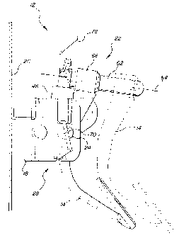
As shown in Figures 2 and 3, the control pedal apparatus I'_ further includes
an
adjustable pedal assembly ?2 with a pedal arm I~ that is moveable in fore and
aft directions
with respect to the support 18. In Fiuure ?, the pedal arm I ~t is shown in
the htrthest
adjustment position in the fore direction in solid lines and in the furthest
adjustment position
in the aft direction in dashed lines. The adjustable pedal assembly ??
preferably includes an
electric motor (not shown) for controllins the movement of the pedal arm I ~I
in the Fore and
aft directions, as is well known in the art. The adjustable pedal assembly ??
can be any of
various adjustable pedal assemblies known in the art. For example, the
adjustable pedal
assembly 22 could be similar to the adjustable pedal assembly in United States
Patent No.
5,632,183 ,
A pivot 24 pivotally supports the adjustable pedal assembly 22 with respect to
the
vehicle structure ?0 and deUines a pivot axis 26 (shown in Figure ~). Tlte
pivot 24 is
preferably comprised of a first pivot member 34 defining a Eirst pivot member
axis 36 and a
second pivot member 38 defining a second pivot member axis 40. The first 36
and second 40
pivot member ayes are collinear to define the pivot axis 26. While two pivot
members 34, 3$
are preferred a single pivot could be used or additional pivot members could
be used to
provide additional pivotal support.
The first 3-1 and second 38 pivot members are longitudinally spaced apart from
one
another to define a clearance space =1? for the pedal arm 14 as the pedal arm
I 4 pivots about
the pivot axis 26. Thus, when the pedal arm l4 is moved from a rest position
to an applied
position, as shown in Fi~_=ure 3, the pedal arm 14 can move between the first
34 and second
38 pivot members without coming into contact with the pivot members 34, 38. If
only a
single pivot member is used, the clearance space =t? between pivot members is
not needed.
The control pedal apparatus l? also includes an electronic throttle control
mechanism
28 attached to the vehicle structure ?0 for controlling an engine throttle 30
shown
schematically in Fi~Ture 1. The electronic throttle control ?3 is responsive
to the pivot ?4 and
provides a signal 3? that corresponds to pedal arm position as the pedal arm
1=1 pivots about
the pivot axis '_'6 between rest and applied positions. Thus, the sienal 32
will vary as the pedal
arm l~l moves from the rest position to the applied position. The electronic
throttle control
mechanism 2S can be any of various electronic throttle control mechanisms
known in the art,
-3
CA 02291903 2003-04-15
76028-123
such as the one described in United States Patent No. 5,819,59 ~ ,
The electronic throttle control ?8 is preferably responsive to the first pivot
member
3~1 to provide the signal 3'? that corresponds to pedal arm position. The
second pivot member
38 preferably provides pivotal balance for the pedal arm 1~4 as the pedal arm
I-I pivots about
the pivot axis 26. It should be understood however that the electronic
throttle control ?8
could also be mounted on the opposite side of the control pedal assembly 1 ?
SlcCh That the
second pivot member 38 provides input to product the signal 32 while the first
pivot member
34 provides additional balance for the pedal arm I=t as it pivots.
The electronic throttle control mechanism 28 preferably includes a first
housin~,~
portion 42 and a second housing portion -t-1, shown in Figure :~. In the
preferred embodiment
the housing portions 4?, 44 partially serve as the support i8 For the control
pedal apparatus
12 and are fixed relative to the vehicle structure 20. The adjustable pedal
assembly 3? is
supported on a bracket ~t6 that is mounted to the housing portions 4'~, 44.
The second
IS housing portion ~t4 includes a first pivotal support 54 and a second
pivotal support 56. The
first pivotal support ~~ receives the first pivot member 34 and the second
pivotal support ~6
receives the second pivot member 3s. As discussed above, the first 34 and
second 38 pivot
members form the pivot 24 about which the pedal arm l 4 pivots.
The bracket 46 includes a first leg 48 and a second leb 50 that extend
downwardly
from a central base member 52. While the bracket 46 is shown with two legs 48,
~0, the
bracket =f6 could also be configured to have only a single leg or could have
additional leg
members. The bracket -16 need only provide partial support for the adjustable
pedal assembly
The bracket 46 is partially installed within the second housing member 44 such
that
the first pivotal support 54 is adjacent to the first leg 48 and the second
pivots! support ~6 is
adjacent to the second ley 50. The first housing portion =12 is attached to
the second housing
portion near the first pivotal support 5~4 to enclose the electronic throttle
control ?8. The first
housing portion 42 preferably includes tab receivers 58 for snap fit
attachment to tabs 60
located on the second housing portion -1-1.
The bracket 46 pivots about the pivot axis ?6 when a force is applied to the
pedal arm
I-I to move the pedal arm 14 from the rest to the applied position. The
electronic throttle
control 28 is fixed with respect to the vehicle structure ?0 such that the
pedal arm 14 moves
in fore and aft directions with respect to the electronic throttle control ?8
and with respect to
the vehicle structure 20. Thus, the adjustable pedal assembly 2? pivots with
respect to the
_a_
CA 02291903 1999-12-07
vehicle structure 20 and moves the pedal arm 14 in fore and aft directions
with respect to the
vehicle structure ?0, while the electronic throttle control '?8 remains fixed
with respect to the
vehicle structure 20. In other words, the pedal arm 14 moves independently
from the
electronic throttle control 28. Additionally, the pedal arm 14 moves in fore
and aft directions
with respect to the pivot 24.
The adjustable pedal assembly 22 includes a guide rod 62 for supporting the
pedal arm
14 and which defines a longitudinal axis 64. The pedal arm 14 moves in the
fore and aft
directions along the longitudinal axis 64. The longitudinal axis 64 is
perpendicular to the pivot
axis 26. Thus, the guide rod 62 is rotatable about the pivot axis 26 along
with the bracket 46
when the pedal arm 14 pivots about the pivot axis 26.
The adjustable pedal assembly 22 further includes a bearing member 66 for
slidably
supporting the pedal arm 14 on the guide rod 62. The bearing member 66 is
preferably a
bushing, however, other bearing members well known in the art can be used. In
the preferred
embodiment, an electric motor is used to drive a screw drive mechanisrri
housed within the
guide rod 62, which causes the bearing member 66 and the pedal arm 14 to move
along the
guide rod 62.
The control pedal apparatus 12 also includes a resilient member 68, shown in
Figure
5, which reacts between the pedal arm 14 and the bracket 46 for providing
resistance as the
pedal arm 14 is moved from the rest position to the applied position. This
resistance provides
a "feel" 16 as the pedal arm 14 pivots that corresponds to the feel that a
driver experiences
in pedal assembly having a cable assembly as part of a mechanical link to the
engine throttle
30. The resilient member 68 is preferably a coil spring with a spring center
70 that is
concentric with the pivot 24. The spring 68 has a first spring end 72 engaging
the pedal arm
14 and a second spring end 74 engaging the bracket 46. In addition to
providing resistance
as the pedal arm 14 is moved to the applied position, the spring 68 returns
the pedal arm 14
to the rest position after a force applied to the pedal arm 14 has been
removed.
The spring 68 is supported by a cylindrical portion 76 that extends inwardly
from the
second housing portion 44 of the electronic throttle control 28, toward the
pedal arm 14.
Thus, the cylindrical portion 76 is located between the pedal arm 14 and the
first leg 48 of the
bracket 46.
While the spring 68 is shown as a coil spring that is supported about pivot
24, other
spring configurations known in the art could also be used. Also, the spring 68
could be
located at a position other than about pivot 24. The main function of the
spring 68 is to act
upon the pedal arm 14 to provide a feel to the driver as the pedal arm 14
pivots.
EIScEI: 65,7.18-Jdl - 5 -
CA 02291903 1999-12-07
A cable attachment member 78 can optionally be supported on one of the pivot
members 34, 38 to support a cable assembly for attachment to the engine
throttle 30. This
configuration would be used in place of the electronic throttle control 28;
i.e., the
configuration is used with a pedal assembly having a mechanical link to the
throttle.
The control pedal apparatus 1'_' of the subject invention provides both an
adjustment
apparatus 22 and an electronic throttle control 28 in an assembly that
requires less packaging
space and which requires Fewer components than prior art control pedals. This
reduces
overall assembly time and reduces material costs. The control pedal apparatus
12 provides
the additional benefits of having a single pivot (24) to pivotally support the
pedal arm 14 in
addition to providing input to the electronic throttle control 28. Thus, the
control pedal
apparatus 12 allows adjustment of the pedal arm 14 in fore and aft directions
without having
to move the electronic throttle control unit 28 along with the pedal arm 14,
and the electronic
throttle control 28 is responsive to the pivot 24 about which the adjustable
pedal assembly 2~
r
rotates.
The invention has been described in an illustrative manner, and it is to be
understood
that the terminology which has been used is intended to be in the nature of
words of
description rather than of limitation.
Obviously, many modifications and variations of the present invention are
possible in
light of the above teachings. It is, therefore, to be understood that within
the scope of the
appended claims, wherein reference numerals are merely for convenience and are
not to be
in any way limiting, the invention may be practiced otherwise than as
specifically described.
tt,~tt: 6s,7as-rat