Sélection de la langue

Search

Sommaire du brevet 2291953 

Énoncé de désistement de responsabilité concernant l'information provenant de tiers

Une partie des informations de ce site Web a été fournie par des sources externes. Le gouvernement du Canada n'assume aucune responsabilité concernant la précision, l'actualité ou la fiabilité des informations fournies par les sources externes. Les utilisateurs qui désirent employer cette information devraient consulter directement la source des informations. Le contenu fourni par les sources externes n'est pas assujetti aux exigences sur les langues officielles, la protection des renseignements personnels et l'accessibilité.

Disponibilité de l'Abrégé et des Revendications

L'apparition de différences dans le texte et l'image des Revendications et de l'Abrégé dépend du moment auquel le document est publié. Les textes des Revendications et de l'Abrégé sont affichés :

  • lorsque la demande peut être examinée par le public;
  • lorsque le brevet est émis (délivrance).
(12) Demande de brevet: (11) CA 2291953
(54) Titre français: OUTIL DE PERFORATION
(54) Titre anglais: PUNCHING AID
Statut: Réputée abandonnée et au-delà du délai pour le rétablissement - en attente de la réponse à l’avis de communication rejetée
Données bibliographiques
(51) Classification internationale des brevets (CIB):
  • A63B 69/34 (2006.01)
  • A63B 69/20 (2006.01)
(72) Inventeurs :
  • CHEN, SHERRY (Taïwan, Province de Chine)
(73) Titulaires :
  • SHERRY CHEN
(71) Demandeurs :
  • SHERRY CHEN (Taïwan, Province de Chine)
(74) Agent: SMART & BIGGAR LP
(74) Co-agent:
(45) Délivré:
(22) Date de dépôt: 1999-12-09
(41) Mise à la disponibilité du public: 2001-04-27
Requête d'examen: 2005-06-30
Licence disponible: S.O.
Cédé au domaine public: S.O.
(25) Langue des documents déposés: Anglais

Traité de coopération en matière de brevets (PCT): Non

(30) Données de priorité de la demande:
Numéro de la demande Pays / territoire Date
09/432,065 (Etats-Unis d'Amérique) 1999-10-27

Abrégés

Abrégé anglais


A punching aid includes a column disposed above a
base, a pad adjustably attached onto the column, and a
flexible device secured between the base and the column
to provide a flexibility to the column relative to the
base. The flexible device includes two couplers secured
to the ends. The base and the column each includes a
stud engaged into and secured to the couplers for
securing the flexible device between the column and the
base. The couplers each has a protrusion and a disc
engaged into the flexible device for solidly securing
the flexible device to the base and the column.

Revendications

Note : Les revendications sont présentées dans la langue officielle dans laquelle elles ont été soumises.


CLAIMS:
1. A punching aid comprising:
a base,
a column provided above said base,
a pad attached onto said column,
a flexible device, and
means for securing said flexible device between
said base and said column to provide a flexibility to
said column relative to said base.
2. The punching aid according to claim 1, wherein
said flexible device includes a lower portion and an
upper portion, said securing means includes means for
fastening said lower portion of said flexible device to
said base and means for fastening said upper portion of
said flexible device to said column.
3. The punching aid according to claim 1, wherein
said flexible device includes a first end, said
securing means includes a first coupler provided on
said first end of said flexible device, a second
coupler provided on said base, and means for locking
said second coupler and said first coupler together.
4. The punching aid according to claim 3, wherein
said second coupler is a stud extended from said base
and having a groove formed therein, said first coupler
includes a hole formed therein for receiving said stud
of said base.
5. The punching aid according to claim 4, wherein
10

said locking means includes a projection extended
inward of said hole of said first coupler and engaged
into said groove of said stud.
6. The punching aid according to claim 5, wherein
said stud further includes a lock slot formed therein
and communicating with said groove of said stud for
receiving said projection of said first coupler.
7. The punching aid according to claim 3, wherein
said locking means includes a fastener engaged through
said second coupler and said first coupler to secure
said second coupler and said first coupler together.
8. The punching aid according to claim 3, wherein
said first coupler includes a protrusion extended
therefrom and engaged into said first end of said
flexible device.
9. The punching aid according to claim 8, wherein
said first coupler includes a disc secured on said
protrusion and engaged in said first end of said
flexible device.
10. The punching aid according to claim 9, wherein
said disc includes at least one opening formed therein
for receiving a material for forming said flexible
device.
11. The punching aid according to claim 1, wherein
said flexible device includes a first end, said
securing means includes a first coupler provided on
said first end of said flexible device, a second
11

coupler provided on said column, and means for locking
said second coupler and said first coupler together.
12. The punching aid according to claim 11,
wherein said second coupler is a stud extended from
said column and having a groove formed therein, said
first coupler includes a hole formed therein for
receiving said stud of said column.
13. The punching aid according to claim 12,
wherein said said locking means includes a projection
extended inward of said hole of said first coupler and
engaged into said groove of said stud.
14. The punching aid according to claim 13,
wherein said stud further includes a lock slot formed
therein and communicating with said groove of said stud
for receiving said projection of said first coupler.
15. The punching aid according to claim 11,
wherein said locking means includes a fastener engaged
through said second coupler and said first coupler to
secure said second coupler and said first coupler
together.
16. The punching aid according to claim 11,
wherein said first coupler includes a protrusion
extended therefrom and engaged into said first end of
said flexible device.
17. The punching aid according to claim 16,
wherein said first coupler includes a disc secured on
said protrusion and engaged in said first end of said
12

flexible device.
18. The punching aid according to claim 17,
wherein said disc includes at least one opening formed
therein for receiving a material for forming said
flexible device.
19. The punching aid according to claim 1 further
comprising means for adjusting said pad relative to
said column.
13

Description

Note : Les descriptions sont présentées dans la langue officielle dans laquelle elles ont été soumises.


CA 02291953 1999-12-09
PUNCHING AID
BACKGROUND OF THE INVENTION
1. Field of the Invention
The present invention relates to a punching aid,
OS and more particularly to a punching aid for home use.
2. Description of the Prior Art
U.S. Patent No. 4,486,016 to Rubin discloses a
typical punching bag support including a flexible
support rod having a lower portion engaged into a base
IO support and detachably secured to the base support with
fasteners. The support rod may not be easily bent
during punching operations.
U.S. Patent No. 5,330,403 to Kuo discloses another
punching device including a support rod having a lower
15 portion squeezed and engaged into a base support, and a
spring engaged on the squeezed portion of the support
rod for forming a flexible punching device. The spring
may not be coupled between the support rod and the base
without the squeezed portion of the support rod, and
20 the squeezed portion of the support rod may be easily
broken while or after punching.
U.S. Patent No. 5,624,358 to Hestilow discloses a
further punching device including a column extended
upward from a pedestal and formed integral as an
integral one piece unit. The column is solidly secured
to or extended from the pedestal such that the column
may not be easily bent while punching. In addition, the
1

CA 02291953 1999-12-09
punching device occupies a great volume which is
adverse for transportation and carrying purposes.
The present invention has arisen to mitigate
and/or obviate the afore-described disadvantages of the
OS conventional punching or boxing aids.
SUMMARY OF THE INVENTION
The primary objective of the present invention is
to provide a punching aid including a flexible
structure for facilitating the punching or boxing
exercises.
The other objective of the present invention is to
provide a punching aid including a detachable structure
for allowing the punching aid to be disassembled and
packaged to a compact configuration.
In accordance with one aspect of the invention,
there is provided a punching aid comprising a base, a
column provided above the base, a pad attached onto the
column, a flexible device, and means for securing the
flexible device between the base and the column to
provide a flexibility to the column relative to the
base.
The flexible device includes a lower portion and
an upper portion, the securing means includes means for
fastening the lower portion of the flexible device to
the base and means for fastening the upper portion of
the flexible device to the column. The pad may be
adjusted relative to the column according to the sizes
2

CA 02291953 1999-12-09
of the users.
The flexible device includes a first end, the
securing means includes a first coupler provided on the
first end of the flexible device, a second coupler
OS provided on the base, and means for locking the second
coupler and the first coupler together. The second
coupler is a stud extended from the base and having a
groove formed therein, the first coupler includes a
hole formed therein for receiving the stud of the base.
The locking means includes a projection extended inward
of the hole of the first coupler and engaged into the
groove of the stud. The stud further includes a lock
slot formed therein and communicating with the groove
of the stud for receiving the projection of the first
coupler.
The locking means includes a fastener engaged
through the second coupler and the first coupler to
secure the second coupler and the first coupler
together. The first coupler includes a protrusion
extended therefrom and engaged into the first end of
the flexible device. The first coupler includes a disc
secured on the protrusion and engaged in the first end
of the flexible device. The disc includes at least one
opening formed therein for receiving a material for
forming the flexible device.
Further objectives and advantages of the present
invention will become apparent from a careful reading
3

CA 02291953 1999-12-09
of a detailed description provided hereinbelow, with
appropriate reference to accompanying drawings.
BRIEF DESCRIPTION OF THE DRAWINGS
FIG. 1 is an exploded view of a punching aid in
OS accordance with the present invention;
FIG. 2 is a perspective view of the punching aid,
in which a portion of the cover is cut off;
FIG. 3 is a cross sectional view taken along lines
3-3 of FIG. 2;
~ FIG. 4 is a plane view of the punching aid;
FIG. 5 is an exploded view illustrating the other
application of the punching aid;
FIG. 6 is a cross sectional view of the punching
aid as shown in FIG. 5; and
FIG. 7 is a cross sectional view illustrating the
application of the punching aid as shown in FIGS. S and
6.
DETAILED DESCRIPTION OF THE PREFERRED EMBODIMENT
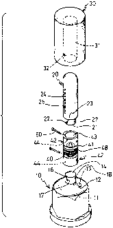
Referring to the drawings, and initially to FIGS.
1-3, a punching aid in accordance with the present
invention comprises a base 10 including a chamber 11
formed therein for receiving fluids and including a
mouth 12 formed in the upper portion thereof and
communicating with the chamber 11 of the base 10 for
receiving the fluids, such as the water, any suitable
liquid, or other particulate materials, such as sand,
gravel, coated or uncoated metallic shot and the like,
4

CA 02291953 1999-12-09
to give the punching aid stability. A cap 13 is
detachably secured onto the mouth 12 of the base 10 for
enclosing the chamber 11 of the base 11 and for
confining the fluids within the base 10. The base 10
OS includes a coupler, such as a stud 14 extended upward
therefrom and having one or more, preferably two,
grooves 16 formed therein. The grooves 16 have an open
upper end and is preferably vertical and have a lock
slot 17 formed in the lower port ion thereof . The stud
14 includes an aperture 18 formed therein for threading
a fastener or a pin 50. The base 10 may also be made to
a solid structure having a suitable stability.
A column 20 is to be secured vertically on top of
the base 10 and includes a coupler, such as a stud 21
provided on the lower port ion thereof . The stud 21 is
similar to the stud 14 of the base 10 and includes one
or more, preferably two, grooves 22 formed therein. The
grooves 22 have an open lower end and is preferably
vertical and have a lock slot 23 formed in the upper
portion thereof. The stud 21 includes an aperture 27
formed therein for threading a fastener or a pin S0.
The column 20 includes one or more longitudinal
channels 24 formed therein and having one or more lock
slots 25 communicating with the respective channels 24.
A striking pad 30 includes a bore 31 formed therein for
receiving the column 20 and includes one or more
projections 32 extended inward of the bore 31 thereof
5

CA 02291953 1999-12-09
for engaging into the channels 24 and/or the lock slots
25 of the column 20 and for setting the pad 30 to
various heights. The pad 30 is preferably made of
spongy or rubber materials far striking purposes, and
OS may be formed into various kinds of shapes, such as a
human body shape (FIG. 4) or a cylindrical shape (FIGS.
1-3). The pad 30 preferably may include an enclosed
(FIGS. 1-3) or open (FIGS. 5-7) upper portion. As best
shown in FIGS. 2 and 3, a barrel 33 is preferably
engaged in and secured in the inner portion of the pad
30 for def fining the bore 31 of the pad 30 and is made
of harder or stronger materials than that for the pad
30, such as plastic materials, and has the projections
32 extended therefrom. The projections 32 are also made
of the stronger materials and thus have a suitable
strength for engaging into the channels 24 and the lock
slots 25 of the column 20 and for supporting the pad 30
on the column 20 at the required height.
A flexible device 40 includes two couplers 42
secured to the ends thereof, such as the upper and the
lower ends thereof for securing or fastening or locking
onto the studs 14, 21 of the base 10 and the column 20
and for providing a flexibility to the column 20
relative to the base 10. The couplers 42 each includes
a hole 43 formed therein for receiving the respective
stud 14, 21 and each includes a projection 44 extended
inward of the hole 43 thereof for engaging into the
6

CA 02291953 1999-12-09
grooves 16, 22 and the lock slots 17, 23 of the studs
14, 21 and for securing the flexible device 40 between
the base 10 and the column 20. The pins 50 may be
engaged through the couplers 42 and the studs 14, 21
OS for further solidly securing the flexible device 40
between the base 10 and the column 20. The flexible
device 40 is preferably made of synthetic or rubber
materials and may be made to a size or a diameter no
less than that of the column 20. However, if the
material is strong enough, the flexible device 40 may
be made to a smaller size than that of the column 20.
The flexible device 40 may further include one or more
peripheral or annular grooves 41 formed therein for
defining one or more peripheral ribs 48 and for
increasing the flexibility to the flexible device 40,
and may include one or more f ins 49 formed in the
annular grooves 41 and coupled between the ribs 48 for
increasing the strength of the flexible device 40.
As best shown in FIG. 3, the couplers 42 each
includes a protrusion 45 extended inward of the
flexible device 40 and a disc 46 formed or provided on
the end portion of the protrusion 45. The protrusion 45
and the disc 46 of each coupler 42 may be engaged in
the flexible device 40 when molding the flexible device
40 onto the couplers 42 such that the flexible device
40 may be solidly secured to the couplers 42. The discs
46 may each further include one or more openings 47
7

CA 02291953 1999-12-09
formed therein. The material for forming the flexible
device 40 may be engaged into the openings 47 of the
discs 46 while molding the flexible device 40 onto the
couplers 42 such that the flexible device 40 may
05 further be solidly secured to the couplers 42.
The most important characteristic for the punching
aid is that the flexible device 40 has the upper and
the lower portions coupled to the column 20 and the
base 10 respectively. None of the arts may provide a
flexible device 40 directly coupled to the base 10 and
the column 20. Although the flexible device 40 is shown
to be coupled to the base 10 and the column 20 with the
engagement between the stud and the coupler, the
flexible device 40 may also be directly coupled to the
base and the column with fasteners without the studs
and the couplers. The column 20 and the pad 30 and/or
the flexible device 40 may be detached or disengaged
from the base 10 such that the column of the punching
aid may be greatly decreased for facilitating the
storing and the transportation thereof.
Referring next to FIGS. 5 and 6, one of the
couplers 420 secured to the flexible device 40 may be a
stud-shaped coupler 420 (FIG. 5) similar to that (14,
21) of the base 10 and the column 20. The column 20 or
the base 10 may include a socket 100 similar to the
couplers 42 as shown in FIGS. 1-3 and having a hole 19
formed therein for receiving the stud-shaped coupler
8

CA 02291953 1999-12-09
420 which may also be secured to the socket 100 with a
projection-lock slot engagement and/or a locking pin.
As shown in FIG. 7, the socket or the stud 21 of the
column 20 may be directly secured to the stud or the
05 socket 15 of the base 10 without the flexible device 40
for decreasing the height of the punching aid and for
being easily stricken by the children.
Accordingly, the punching aid in accordance with
the present invention includes a flexible structure for
facilitating the punching or boxing exercises, and
includes a detachable structure for allowing the
punching aid to be disassembled and packaged to a
compact configuration.
Although this invention has been described with a
certain degree of particularity, it is to be understood
that the present disclosure has been made by way of
example only and that numerous changes in the detailed
construction and the combination and arrangement of
parts may be resorted to without departing from the
spirit and scope of the invention as hereinafter
claimed.
9

Dessin représentatif
Une figure unique qui représente un dessin illustrant l'invention.
États administratifs

2024-08-01 : Dans le cadre de la transition vers les Brevets de nouvelle génération (BNG), la base de données sur les brevets canadiens (BDBC) contient désormais un Historique d'événement plus détaillé, qui reproduit le Journal des événements de notre nouvelle solution interne.

Veuillez noter que les événements débutant par « Inactive : » se réfèrent à des événements qui ne sont plus utilisés dans notre nouvelle solution interne.

Pour une meilleure compréhension de l'état de la demande ou brevet qui figure sur cette page, la rubrique Mise en garde , et les descriptions de Brevet , Historique d'événement , Taxes périodiques et Historique des paiements devraient être consultées.

Historique d'événement

Description Date
Demande non rétablie avant l'échéance 2006-12-11
Le délai pour l'annulation est expiré 2006-12-11
Inactive : CIB de MCD 2006-03-12
Réputée abandonnée - omission de répondre à un avis sur les taxes pour le maintien en état 2005-12-09
Lettre envoyée 2005-07-21
Requête en rétablissement reçue 2005-06-30
Exigences pour une requête d'examen - jugée conforme 2005-06-30
Toutes les exigences pour l'examen - jugée conforme 2005-06-30
Lettre envoyée 2005-01-17
Requête d'examen reçue 2005-01-04
Modification reçue - modification volontaire 2005-01-04
Exigences de rétablissement - réputé conforme pour tous les motifs d'abandon 2005-01-04
Exigences de rétablissement - réputé conforme pour tous les motifs d'abandon 2004-12-23
Inactive : Abandon.-RE+surtaxe impayées-Corr envoyée 2004-12-09
Réputée abandonnée - omission de répondre à un avis sur les taxes pour le maintien en état 2004-12-09
Lettre envoyée 2004-01-23
Exigences de rétablissement - réputé conforme pour tous les motifs d'abandon 2003-12-29
Réputée abandonnée - omission de répondre à un avis sur les taxes pour le maintien en état 2003-12-09
Inactive : Grandeur de l'entité changée 2001-12-20
Demande publiée (accessible au public) 2001-04-27
Inactive : Page couverture publiée 2001-04-26
Inactive : CIB en 1re position 2000-02-08
Inactive : Certificat de dépôt - Sans RE (Anglais) 2000-01-12
Demande reçue - nationale ordinaire 2000-01-10

Historique d'abandonnement

Date d'abandonnement Raison Date de rétablissement
2005-12-09
2005-06-30
2004-12-09
2003-12-09

Taxes périodiques

Le dernier paiement a été reçu le 2004-12-23

Avis : Si le paiement en totalité n'a pas été reçu au plus tard à la date indiquée, une taxe supplémentaire peut être imposée, soit une des taxes suivantes :

  • taxe de rétablissement ;
  • taxe pour paiement en souffrance ; ou
  • taxe additionnelle pour le renversement d'une péremption réputée.

Les taxes sur les brevets sont ajustées au 1er janvier de chaque année. Les montants ci-dessus sont les montants actuels s'ils sont reçus au plus tard le 31 décembre de l'année en cours.
Veuillez vous référer à la page web des taxes sur les brevets de l'OPIC pour voir tous les montants actuels des taxes.

Historique des taxes

Type de taxes Anniversaire Échéance Date payée
Taxe pour le dépôt - petite 1999-12-09
TM (demande, 2e anniv.) - générale 02 2001-12-10 2001-12-05
TM (demande, 3e anniv.) - générale 03 2002-12-09 2002-12-04
TM (demande, 4e anniv.) - générale 04 2003-12-09 2003-12-29
Rétablissement 2003-12-29
Rétablissement 2004-12-23
TM (demande, 5e anniv.) - générale 05 2004-12-09 2004-12-23
Requête d'examen - générale 2005-01-04
2005-06-30
Titulaires au dossier

Les titulaires actuels et antérieures au dossier sont affichés en ordre alphabétique.

Titulaires actuels au dossier
SHERRY CHEN
Titulaires antérieures au dossier
S.O.
Les propriétaires antérieurs qui ne figurent pas dans la liste des « Propriétaires au dossier » apparaîtront dans d'autres documents au dossier.
Documents

Pour visionner les fichiers sélectionnés, entrer le code reCAPTCHA :


Pour visualiser une image, cliquer sur un lien dans la colonne description du document. Pour télécharger l'image (les images), cliquer l'une ou plusieurs cases à cocher dans la première colonne et ensuite cliquer sur le bouton "Télécharger sélection en format PDF (archive Zip)" ou le bouton "Télécharger sélection (en un fichier PDF fusionné)".

Liste des documents de brevet publiés et non publiés sur la BDBC .

Si vous avez des difficultés à accéder au contenu, veuillez communiquer avec le Centre de services à la clientèle au 1-866-997-1936, ou envoyer un courriel au Centre de service à la clientèle de l'OPIC.


Description du
Document 
Date
(aaaa-mm-jj) 
Nombre de pages   Taille de l'image (Ko) 
Dessin représentatif 2001-04-11 1 10
Description 1999-12-08 9 292
Abrégé 1999-12-08 1 16
Revendications 1999-12-08 4 103
Dessins 1999-12-08 6 106
Revendications 2005-01-03 4 118
Certificat de dépôt (anglais) 2000-01-11 1 164
Rappel de taxe de maintien due 2001-08-12 1 116
Courtoisie - Lettre d'abandon (taxe de maintien en état) 2004-01-22 1 176
Avis de retablissement 2004-01-22 1 168
Rappel - requête d'examen 2004-08-09 1 117
Courtoisie - Lettre d'abandon (taxe de maintien en état) 2005-01-16 1 175
Avis de retablissement 2005-01-16 1 165
Courtoisie - Lettre d'abandon (requête d'examen) 2005-02-16 1 166
Accusé de réception de la requête d'examen 2005-07-20 1 175
Avis de retablissement 2005-07-20 1 169
Courtoisie - Lettre d'abandon (taxe de maintien en état) 2006-02-05 1 174
Taxes 2002-12-03 1 42
Taxes 2004-12-22 2 60