Note : Les descriptions sont présentées dans la langue officielle dans laquelle elles ont été soumises.
CA 02292180 1999-12-14
SWASH-PLATE TYPE COMPRESSOR IN WHICH IMPROVEMENT IS MADE
AS REGARDS ENGAGEMENT MECHANISM OF PISTON AND SHOE
The present invention relates to a awash-plate type
compressor and, more particularly, to an engagement
structure of a piston and a shoe which are included in the
awash-plate type compressor.
Conventional awash-plate type compressors are
disclosed in each of Japanese Patent Application Laid-Open
Nos. 135990/1986, 65509/1974, and 138474/1981. Each of the
awash-plate type compressors comprises a rotatable shaft
driven to be caused a rotation thereof, a awash plate
connected to the rotatable shaft to rotate together with
the rotatable shaft, a piston having a concave part facing
the awash plate, and a shoe having a spherical convex part
inserted in the concave part. When the rotatable shaft
rotates, the shoe slides along the awash plate and converts
the rotation of the rotatable shaft to a reciprocating
movement of the piston in cooperation with the awash plate.
Among these conventional awash-plate type compressors,
the compressor using a double-head piston is called a
double awash-plate type compressor. The compressor using a
piston provided with a compression head only on one end is
palled a single awash-plate type compressor. In the single
CA 02292180 1999-12-14
2
sash-plate type compressor, the concave part of the piston
is usually made aloag a single spherical surface having a
radius of curvature which is substantially equal to that of
the spherical convex part.
During operation of each of the conventional swash-
plate type compressors, the shoe performs wobbling movement
thereof in the vonoave part in avaordanae with the rotating
movement of the swash plate. Therefore, the maintaining of
excellent lubricating properties is demanded between the
spherical convex part of the shoe and the concave part of
the piston.
However, the swash-plate type compressor in previous
technique has disadvantages in that lubricant oil cannot
easily enter between the concave part of the piston and the
spherical convex part of the shoe. This is because the
concave part of the piston substantially coincides with the
spherical convex part of the shoe, there is little
clearance between both sliding surfaces.
Therefore, a large force acts on the concave part of
the piston, thereby generating wear by sliding movement
with the shoe. Particularly in the initial stage of
operation of the swash-plate type compressor, since the
concave part does not sufficiently fit with the spherical
convex surface of the shoe, wear amount is considerable.
Moreover, an abnormal wear is sometimes generated in the
concave part of the pistoa.
To prevent this, it is described, for example, in U.S.
Patent No. 4,734,014 that the convex curved surface of the
CA 02292180 1999-12-14
3
shoe is formed into a spherical surface having a smaller
curvature radius than that of the spherival surface of the
concave part and that the vertex of the spherical curved
surfave is: formed into a flat part. In the compressor
described in this U.S. patent, an oil reservoir is formed
between the flat part of the shoe and the accommodation
concave part, which is advantage for the lubricating
properties.
However, when the end of the flat surface of the shoe
slides on the inner surface of the concave part, the local
wear of the concave part is more promoted. Therefore, a
clearance is generated in a part different from the
clearance disposed beforehand. In addition, the load of
the local force causes partial deformation in the concave
part. So that, the life of the compressor is shortened.
Additionally, as a result of reinforcement of relative
vibration of the shoe, the generation of noise during the
operation is also promoted.
It is therefore an object of the present invention to
provide a swash-plate type compressor in which local wear
or partial deformation is not caused in the concave portion
although lubricant oil is readily introduced between a
concave portion of a piston and a spherical convex portion
of a shoe in an initial stage of the compressor and which.
It is another object of the present invention to
provide an engagement structure between the piston and the
shoe in the swash-plate type compressor, in which wear is
CA 02292180 1999-12-14
4
promoted without dragging or tearing to thereby make the
concave part of the piston fit to the spherical convex
portion of the shoe.
Other objects of the present invention will become
clear as the description proceeds.
According to an aspect of the present invention,
there is provided a awash-plate type compressor which
comprises a rotatable shaft driven to be caused a rotation
thereof, a awash plate connected to the rotatable shaft to
rotate together with the rotatable shaft, a piston having a
concave part facing the awash plate, and a shoe having a
spherical convex part inserted in the concave part. The
shoe is slidable along the awash plate for converting the
rotation of the rotatable shaft to a reciprocating movement
of the piston in cooperation with the awash plate. The
piston further has a protrusion formed in the concave part
to leave a clearance between the concave part and the
spherical convex part.
It map be arranged that the protrusion is formed at a
bottom of the concave part.
It map be arranged that the concave part has at least
two spherical surfaces which partially superpose to each
other to form the protrusion between adjacent ones of the
spherical surfaces.
It may be arranged that the piston has a pair of
opposite surfaces defining a groove therebetween, the
concave part being formed in one of the opposite surfaces,
the awash plate having a peripheral portion inserted in the
CA 02292180 1999-12-14
groove.
It may be arranged that another of the opposite
surfaces is formed with an additional concave part, the
compressor further comprising an additional shoe having a
5 spherical convex part inserted in the additional concave
part, the additional shoe being slidable along the awash
plate for converting the rotation of the rotatable shaft to
the reciprocating movement of the piston is cooperation
with the awash plate and the first-mentioned shoe.
It may be arranged that the piston further has an
additional protrusion formed in the additional concave part
to leave a clearance between the additional concave part
and the spherical convex part of the additional shoe.
It may be arranged that the additional protrusion is
formed at a bottom of the additional concave part.
It may be arranged that the additional concave part
has at least two spherical surfaces which partially
superpose to each other to form the protrusion between
adjacent ones of the spherical surfaces.
According to another aspect of the present invention,
there is provided a piston and shoe engagement structure of
a awash-plate type compressor provided with a awash plate
for rotatiag around a rotatable shaft and performing
reciprocating movement aloag the rotatable shaft, and a
piston having a groove for passing the awash plate to
convert the movement of the awash plate to the
reciprocating movement via a shoe, wherein end surfaces of
the groove are provided with concave parts having circular
CA 02292180 1999-12-14
6
surface shapes to hold a spherical surface part of the shoe,
the each of concave parts having a bottom part provided
with a conveu part.
It may be arranged that, by superposing at least two
spherical surfaces different in central position, the
aonves part is formed in a boundary part between the
spherical surfaces.
Fig. 1 is a longitudinal sectional view of a swash-
plate type compressor according to an embodiment of the
present invention;
Fig. 2 is an enlarged sectional view of a main
portion of the awash-plate type compressor of Fig. 1; and
Fig. 3 is a schematic sectional view for describing
in detail the main portion of Fig. 2.
With reference to the drawing, description will be
made hereinafter as regards a awash-plate type compressor
according to an embodiment of the present invention.
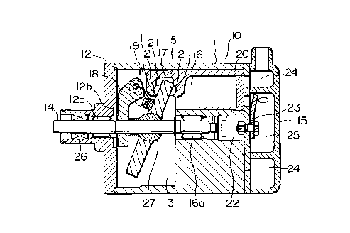
Referring to Fig. 1, the awash-plate type compressor
10 is also called a single awash-plate type compressor aad
usable in an air conditioner for an automobile. The swash-
plate type compressor 10 includes a cylinder block 11
integrally formed with a housing having an opening on one
end thereof, a front housing 12 disposed to cover the
opening of the housing, and a cylinder head 15 disposed to
close the other end of the cylinder block 11 via a valve
plate device 23, so that the entire outer contour is formed.
CA 02292180 1999-12-14
7
The cylinder block 11 has a plurality of cylinder bores 16
constituted of through holes passing from one end toward
the other end. The cylinder bores 16 are formed in
equiangular positions on a ciroumference. A discharge
chamber 25 and a suction chamber 24 are divided/formed by
the walls of the valve plate device 23 and the cylinder
head 15.
A crank chamber 13 is defined inside by the cylinder
block 11 and the front housing 12. A rotatable shaft 14 is
extended through the crank chamber 13 from a protruding
part of front housing 12 to the cylinder block 11 in an
axial direction. The rotatable shaft 14 is rotatably
supported by the front housing 12 and the cylinder block 11
via bearings 12a, 16a. An automobile engine (not shown)
rotates the rotatable shaft 14 for driving the awash-plate
type compressor. Additionally, a reference numeral 26
denotes a seal member for shielding the shaft from the
outside.
A spherical support member 27 is fitted over the
rotatable shaft 14 to be slidable along the rotatable shaft
14 in the axial direction. A awash plate 17 is disposed
around the rotatable shaft 14 in the crank chamber 13 and
supported on the spherical support member 27 to be capable
of sliding along or wobbling around the spherical support
member 27. A rotor 18 is fixed to the rotatable shaft 14.
One end of the rotor 18 is supported by the inner wall of
the front housing 12 via a bearing 12b. The other end of
the rotor 18 is connected to the awash plate 17 through a
CA 02292180 1999-12-14
8
connecting part or hinge mechanism 19.
Furthermore, a plurality of pistons 20 are inserted
in the cylinder bores 16, respectively. Each of the
pistons 20,is slidable in the axial direction and includes
a neck portion 5 having a pair of opposite surfaces which
are define a groove 21 therebetween. The awash plate 17
has a peripheral portion is inserted in the groove 21. A
pair of concave parts 1 is formed to the opposite surfaces
of the neck portion 5. The concave parts 1 are opposite to
each other in the axial direction.
Hemispherical shoes 2 are interposed between the
concave parts 1 and the awash plate 17. Each of the shoes
2 is fitted in each of the concave parts 1 in the manner
which will later be described in detail.
A pressure control device 22 is disposed for
adjusting a pressure in the crank chamber 13. In response
to the pressure of the crank chamber 13, the awash plate 17
has an inclined angle adjusted with respect to the
rotatable shaft 14 in the manner known in the art. The
awash-plate type compressor has a compression capacity
determined in accordance with the inclined angle of the
awash plate 17.
i~lhen the automobile engine rotates the rotatable
shaft 14, the awash plate 17 is rotated together with the
rotatable shaft 14 through the rotor 18 and the hinge
mechanism 19. As a result, the peripheral part of the
awash plate 17 performs movement in a circular arc shape
along the rotatable shaft 14 centering on the center part
CA 02292180 1999-12-14
9
on the rotatable shaft 14.
With the rotation of the awash plate 17, the piston
20 is alternately pressed back and forth via the shoes 2 to
reciprocate/slide in the cylinder bore 16. Fluid is drawn
between the inside of a suction valve cylinder bore (not
shown) and the head of the piston 20 from the suction
chamber 24 by the reciprocating movement of the piston 20,
and is then discharged to the discharge chamber 25 via a
discharge valve by the movement of the piston 20 toward the
right as seen in Fig. 1.
Referring to Fig. 2, the peripheral portion of the
swash plate 17 is inserted or accommodated in the groove 21
in the neck portion 5 of the piston 20. The shoes 2 are
interposed between the concave parts and the.swash plate 17,
respectively. Each of the shoes 2 has a spherical convex
part 2a and a flat surface. The spherical convex part 2a
is in sliding contact with the corresponding concave part 1
and. The flat surface is in sliding contact with the
peripheral portion of the swash plate 17. It is to be
noted here that each of the concave parts 1 has a
protrusion 3 in its center part.
Referring to Fig. 3, each of the concave parts 1 is
constituted of a first spherical surface having a radius R1
and a second spherical surface having a radius R2. The
first and the second spherical surfaces have centers of
curvature spaced to each other and partially superpose to
each other to form the protrusion 3 therebetween. In this
connection, the radii R1 and R2 are determined equal to
CA 02292180 1999-12-14
each other. Additionally, Fig. 3 shows an example in which
each of the radii Rl and R2 is determined to be smaller
than a radius R3 of the spherical convex part 2a of the
shoe 2. It is preferable that the protrusion 3 has a
5 height Dl of about 1 to 20 Wn.
Turning back to Fig. 2, by the shape relation between
the spherical convex part 2a of the 2 and the concave part
1 the piston 20, a clearance 4 is,formed therebetween.
This enables refrigerant gas to easily enter the clearance
10 4. As a result, mist-state lubricant oil in the gas goes
even into the bottom part of the concave part 1 which is
the receiving seat. Therefore, since the lubricant oil is
present on the sliding surface in the initial stage, wear
is generated without dragging or tearing.
As described above, the protrusion 3 provides an
effective fitting property of the shoe 2 and the concave
part 1 as a shoe receiving seat. In other words, the shoe
2 appropriately wears because of the concave part 1 as the
shoe receiving seat. As a result, the durability of the
compressor is enhanced.
While the present invention has thus far been
described is connection with a single embodiment thereof,
it will readily be possible for those skilled in the art to
put this invention into practice in various other manners.
For example, the concave part of the piston map be
constituted of three or more spherical surfaces, adjacent
ones of which are partially superposed to each other. It
CA 02292180 1999-12-14
11
is a matter of course that the protrusion can be formed in
the various manner known in the art.