Note : Les descriptions sont présentées dans la langue officielle dans laquelle elles ont été soumises.
Title: WINDOW DRAIN
BACKGROUND OF THE INVENTION
1. Field of the invention:
This invention relates, in general, to drainage systems for buildings and,
particularly, to a window drain.
2. Description of the prior art:
In the wall construction for buildings, usually the sill of the window frame
merely
rests upon the boarding and, until now, no efficient devices to prevent the
penetration of
water or moisture under the window sill have been developed and successfully
used.
As a direct result, rain water infiltrates into under the sill and leaks down
through the
wall of the building and damages ceilings and plastered walls. If the house
happens to
be covered with a stucco finish, the water also enters between the furring and
the
stucco, so that the stucco becomes discolored and sometimes falls away beneath
the
window.
Despite various improvements in the existing window drains, the latter still
suffer
from drawbacks which are seemingly inherent in their basic concepts. For
example,
United States Patent No. 2,648,107, granted on August 11, 1953 to Bates for a
"Drip
deflector", discloses a device for attachment to a window frame. The device
comprises
an elongated rectangular attaching strip, adapted to be attached to the under
side of a
window sill. An elongated rectangular drip deflecting flange is carried by the
attaching
strip and projects outwardly and downwardly from a longitudinal side edge
thereof and
beyond the outer edge of the window sill.
1
CA 02292301 2000-02-09
Guards, carried by the flange, adjacent opposite ends, extend upwardly and
downwardly
for attachment to the stiles of the window frame. In its drip deflector
configuration,
Bates structure has a number of shortcomings. First, the sill of the window
frame rests
directly on the elongated rectangular attaching strip, thereby no space for
collecting and,
then, draining the water is provided. Second, since no rear upstanding rib or
flange is
used, the leakage of water towards the back of the window frame cannot be
prevented.
Third, the manner of attachment of the drip deflector to the sill of the
window frame by
a series of nails, introduced from under the drip deflector, requires a
completion of this
operation prior the window frame is installed in a building wall.
United Patent No. 3,845,599, granted November 5, 1974 to Jolly, describes a
"Window drain valve" wherein the recesses, which accommodate the panes in an
extruded aluminum window frame, may be drained. Means are provided to prevent
water draining from the recesses to enter into the building in adverse wind
conditions.
This is achieved by the provision of a drain valve having an inflow
compartment and an
outflow compartment, separated by a depending web with a float valve in the
inflow
compartment. The latter named valve closes the communication between the
window
sill recess and the drain valve, when the outlet of the outflow compartment is
subjected
to external wind pressure. This window drain can be considered as having two
disadvantages. First, the use of valves renders the device very complicated.
Second,
the reliability of the system is quite questionable, especially in severe
meteorological
conditions.
United States Patent No. 4,555,882, granted December 3, 1985 to Moffitt et all
for
a "Moisture guard for window frames, door jambs and the like" discloses a
device for
2
CA 02292301 2000-02-09
preventing water damage to the interior of a building, caused by moisture,
leaks, rain,
snow or the like. The moisture guard comprises a metallic facing fixed to a
plastic
molding. The sill of a window frame is seated on the metallic facing. An
integrally
formed upstanding rear flange is located at the rear edge of the base and an
integrally
formed depending front flange is disposed at the forward edge of the base. At
each end
of the base is located an integrally formed upstanding end flange that
embraces the
adjacent window structure. The end flange has a vertical end wall and a
vertical side
wall. There are two basic disadvantages to this moisture guard design. First,
the sill of
the window rests directly on the metal facing and, thus, no space for water
collection is
provided. Second, the metal facing is not provided with a sloping surface for
drainage.
International Application WO 98/32942, published July 30, 1998 under the
Patent
Cooperation Treaty, for a "Diverter for wall drainage", inventors Burroughs et
al,
describes a diverter positioned directly beneath a wall component. The
diverter
includes an upper surface that slopes toward the wall exterior, a plurality of
downwardly sloped channels and a cover over the outer ends of the ribs which
form the
channels. The cover forms drainage openings at the ends of the channels. Two
important shortcomings characterize this diverter. First, no back and lateral
flanges, to
confront the juxtaposed elements of the window structure, are provided.
Second, the
structure is not unitary formed, a separate cover being used.
3
CA 02292301 2000-02-09
SUMMARY OF THE INVENTION
There is, accordingly, a need for a window drain which overcomes the
disadvantages
of the prior art.
It is the primary objective of the present invention to provide a window drain
which is
efficient and reliable.
It is another objective of the present invention to provide a window drain,
well
engineered, forming a one piece structure.
It is yet another objective of the present invention to provide versatile
window drains,
adaptable to be assembled with standard windows having different widths and
lengths.
The present invention is directed, in a first variant, to a window drain
adaptable to be
positioned beneath a sill window. The window comprises, besides the sill,
opposed jambs
and a window flange. The window drain includes a base having a substantially
rectangular
shape in plane with a horizontally extending lower surface and a sloping
downwardly and
outwardly upper surface. The base also incorporates a front flange, which
projects
perpendicularly and downwardly from the front edge of the base, and an
upstanding rear
rib, situated at the rear edge of said base, from which it extends
perpendicularly. The base
also comprises an end flange, located at each lateral edge of the base. The
end flange
includes an upstanding end wall projecting from the lateral edge, and a front
wall coplanar
with the front flange and extending upwardly and downwardly from the base. The
base is
also provided with supports, spacedly disposed on the sloping downwardly and
upwardly
upper surface. The supports have their tops coplanar. On the front flange are
disposed
several spacers having their outsurfaces coplanar. The window drain, as
disclosed, is
adaptable to accommodate a window having a width, measured between the back of
the sill
4
CA 02292301 2000-02-09
and the back of the window flange, equal to the distance between the front
face of the
upstanding rear rib and the outsurfaces of the spacers.
The present invention is also directed, in a second embodiment, to a window
drain
adaptable to be positioned beneath the sill of a window. The window comprises,
the sill,
S opposed jambs and a window flange. The window drain has a substantially
rectangular
shape in plan and includes a base with a horizontally extending lower surface
and a sloping
downwardly and outwardly upper surface. The base is also provided with a front
flange
projecting perpendicularly and downwardly from the front edge. The base
incorporates, as
well, an upstanding rear rib, situated proximate to the back edge of the base,
from which it
extends perpendicularly. The upstanding rear rib is provided with several
spaced apertures
along its length. The base also includes a supplementary rear rib, situated
behind and
parallel to the upstanding rear rib, and projecting from the back edge of the
base. At each
lateral edge of the base, there is an end flange adaptable to be attached to a
vertical element
of the window structure. The end flange comprises an upstanding end wall,
projecting from
the lateral edge, and a front wall coplanar with the front flange. The front
wall extends
upwardly and downwardly from the base. Each end flange is provided with
openings
adaptable to use attachment elements for securing the window drain, when
installed. The
base contains, as well, window supports, spacedly disposed on the sloping
downwardly and
outwardly upper surface. The tops of the window supports are coplanar with the
top of the
upstanding rear rib. The top of the supplementary rear rib is relatively
higher than the top
of the upstanding rear rib. Spacers are disposed on the front flange. The
window drain,
according to this variant, is so designed, that the distance between the
supplementary rear
rib and the front faces of said spacers is adaptable to accommodate a window
having the
5
CA 02292301 2000-02-09
widest standard width, respectively the largest distance between the back edge
of the sill
and the back of the window flange. The window drain is also so designed, that
the distance
between intermediary lines, situated between the supplementary rear rib and
the upstanding
rear rib, on one side, and the front faces of the spacers, on the other side,
are adaptable to
accommodate windows of intermediary widths, respectively intermediary
distances
between the back edge of the sill and the back of the window flange.
The present invention is directed, in yet another embodiment, to a window
drain
adaptable to be positioned beneath a sill of a window. The window comprises,
the sill,
opposed jambs and a window flange.
The window drain has a substantially rectangular shape in plan and includes a
base
with a horizontally extending lower surface and with a sloping downwardly and
outwardly
upper surface. The base is also provided with a front flange projecting
perpendicularly and
downwardly from the front edge of the base. The base is provided, as well,
with an
upstanding rear rib, situated proximate to the back edge of the base, from
which it extends
perpendicularly. A supplementary rear rib, situated behind and parallel to the
upstanding
rear rib and projecting from the back edge of the base is also provided. At
each lateral edge
of the base, there is an end flange which comprises an upstanding end wall
projecting from
the lateral edge and a front wall coplanar with the front flange and extending
upwardly and
downwardly from the base. Each of the end flanges is provided with openings
adaptable to
use attachments for securing the window drain when installed. Use is made of
window
supports, which are spacedly disposed on the sloping downwardly and outwardly
upper
surface and have its coplanar tops. Spacers are provided on the front flange.
The tops of
6
CA 02292301 2000-02-09
the upstanding rear rib and supplementary rear rib are coplanar and relatively
higher than
the tops of the window supports.
Conveniently, the window drain, described above, can be used with a window
having
the narrowest standard width. In this case, the supplementary rear rib,
together with the
part of the base between the upstanding rear rib and the supplementary rear
rib, are cut and
discarded. Thus, when the window is installed, the back of the sill abuts and
confronts the
front of the upstanding rear rib.
Optionally, when the above described window drain is used with a window having
an
intermediary width, the height of the upstanding rear rib is reduced by
cutting it to the level
of the tops of the window supports. Several spaced apertures, disposed along
the length of
the upstanding rear rib are used in this embodiment.
Optionally, the window supports stretch outwardly from the upstanding rear rib
up to
just beyond the front edge of the base, where they form front ends, coplanar
with the
spacers.
Conveniently, the above window supports are each provided, adjacent the
upstanding
rear rib with a recess. All formed recesses are linearly located and adaptable
to be used to
lodge a compressible cord.
Optionally, each of the support means has a truncated cone form.
BRIEF DESCRIPTION OF THE DRAWINGS
Although the characteristic features of the invention will be particularly
pointed out in
the claims, the invention itself, and the manner in which it may be made and
used, may be
better understood by refernng to the following description taken in connection
with the
7
CA 02292301 2000-02-09
accompanying drawings, forming part thereof, wherein like reference numerals
refer to like
parts, throughout the several views in which:
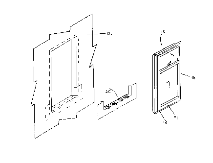
Figure 1 illustrates a perspective view, in spaced relation, of a window drain
together
S with a window and a building wall;
Figure 2 illustrates a vertical section view of the window drain according to
the first
embodiment of the present invention;
Figure 3 illustrates a perspective view of the window drain according to the
first
embodiment;
Figure 3a illustrates a diagrammatical representation of the window drain
according to
the first embodiment;
Figure 4 illustrates a perspective view of the window drain according to the
second
embodiment;
Figure 4a illustrates a diagrammatical view of the window drain according to
the
second embodiment; and
Figure 5 illustrates a diagrammatical view of the window drain according to
the third
embodiment.
DESCRIPTION OF THE PREFERRED EMBODIMENTS
Referring now to the drawings, and initially to Fig 1, there is shown a window
10
ready to be mounted in a building wall 12. Window 10 comprised a sill 14,
opposed jambs
16 and a window flange 18.
8
CA 02292301 2000-02-09
With reference to the Figs. 2, 3 and 3a, there is shown in a first embodiment,
a
window drain, generally indicated at 20. The latter is positioned beneath sill
14 and is
seated on a paper flashing 22.
Window drain 20, which is advantageously formed by molding, comprises a base
24
having a horizontally extending lower surface 26 and a sloping downwardly and
outwardly
upper surface 28. Base 24 has a substantially rectangular shape in plan.
Horizontally
extending lower surface 26 of base 24 lies directly on paper flashing 22.
A front flange 30 projects perpendicularly and downwardly from the front edge
32 of
base 24. Front flange 30 is integrally formed with base 24 and abuts against
paper flashing
22. The latter extends from under base 24 and is disposed on building wall 12.
An upstanding rear rib 34 is situated at the rear edge 36 of base 24, from
which it
extends perpendicularly and upwardly and with which it is integrally formed.
An end flange 38 is located at each lateral edge 40 of base 24 and is
integrally formed
with the latter. Each end flange 38 embraces a vertical element of the window
structure
(not shown) and comprises an upstanding end wall 42, projecting upwardly from
lateral
edge 40, and a front wall 44, coplanar with front flange 30 and extending
upwardly and
downwardly from base 24. Front wall 44 is provided, in its upwardly extending
part, with
openings 46 through which nails or screws may be passed and driven, to firmly
secure
window drain 20 to the window structure (not shown).
Several window supports 48 are spacedly disposed on sloping downwardly and
outwardly upper surface 28 and stretch out forwardly from and perpendicularly
to
upstanding rear rib 34. Window supports 48 extend up to beyond front edge 32
of base 24,
where they form front ends 50. The latter are continued downwards by spacers
52 with
9
CA 02292301 2000-02-09
which they have coplanar outsurfaces. The top of upstanding rear rib 34 is
relatively higher
than the tops of window support 48.
Windows 10 come in standard widths and window drain 20 of the present
invention
would be commensurable with a standard window having a determined width.
After window drain 20 has properly been installed, window 10 is placed on it,
so that
its sill 14 rests on windows supports 48 and its back abuts upstanding rear
rib 34.
Concomitantly, window flange 18 contacts front ends 50 and spacers 52 and
thus, it is kept
at a certain distance from front flange 30 and, thereby, gaps are formed.
Window drain 20 is rendered watertight by the provision of caulking seams,
respectively, an upper 54 and a lower 56. Upper caulking seam 54 is provided
between the
upper part of upstanding rear rib 34 and the adjacent part of sill 14. Lower
caulking seam
56 is provided between base 24 and the adjacent window structure.
The water collected in the compartments formed by upstanding rear rib 34 and
window supports 48 is diverted outwardly and downwardly through the above
described
gaps. To protect a siding 58 which covers the front of a building from drained
water, a
counterflashing 60 is provided. The latter is attached beneath the lower part
of front flange
30. An extension 62 of counterflashing 60 is directed outwardly and downwardly
from
siding 58.
Window drain 20, described in this embodiment, is produced with a determined
width, but may be adapted, in situ, for different lengths. This can be
achieved, basically, by
cutting window drain 20 in two and adding or removing a segment.
Optionally, window drain 20 can be molded in two entities: a left side and a
right side,
which can be joined together.
CA 02292301 2000-02-09
In a second embodiment, shown diagrammatically in Figs. 4 and 4a, window drain
64
is designed to accommodate windows 10 of different standard widths. To this
end, the
above described embodiment is modified as follows: a base 66, wider than base
24, is used.
Base 66 incorporates a supplementary rear rib 68. The latter is situated
behind and parallel
to upstanding rear rib 34 and projects outwardly from the back edge of base
24. In this
embodiment the top of upstanding rear rib 34 is coplanar with the tops of
window supports
48, while the top of supplementary rear rib 68 is relatively higher. The
distance between
supplementary rear rib 68 and front ends 50 or spacers 52 is adaptable to
accommodate a
window 10 having the widest standard width, respectively the largest distance
between the
back edge of sill 14 and the back face of window flange 18.
Distances between intermediary lines situated between rear rib 68 and
upstanding rear
rib 34, on one side, and front ends 50 or the front faces of spacers 52, on
the other side, are
adaptable to accommodate windows 10 of intermediary distances between the back
edge of
sill 14 and the back of window flange 18. When the back edge of sill 14 is
situated
anywhere behind upstanding rear rib 34 including even direct contact with
supplementary
rear rib 68, an upper caulking seam 54, formed substantially between the lower
edge of sill
14 and the top of supplementary rear rib 68, is used.
When the lower edge of sill 14 is situated on an intermediary line, as
described above,
water collected in a U-channel, formed by supplementary rear rib 68,
upstanding rear rib 34
and base 24, is drained towards the exterior of the building. To this end,
upstanding rear rib
34 is provided with several spaced apertures 72, disposed along its length.
Apertures 72
start at the level of sloping downwardly and outwardly upper surface 28 and
have a
11
CA 02292301 2000-02-09
relatively limited upward extension. They are formed by exerting a limited
force on zones
corresponding to the apertures. These zones are of reduced mechanical
strength.
In a third embodiment shown in Fig. 5, a window drain 74 is adaptable to
accommodate, in situ, windows 10 of different standard widths. To this end,
the above
described embodiment is modified as follows: upstanding rear rib 34 and
supplementary
rear rib 68 are provided with coplanar tops, which are relatively higher than
the tops of
window supports 48. When a window drain 74 is used for a window 10 having the
narrowest standard width, supplementary rear rib 68 together with the part of
base 24,
between upstanding rear rib 34 and supplementary rear rib 68, are cut and
discarded. In this
case, the back of sill 14 abuts upstanding rear rib 34. A corresponding upper
caulking seam
54 is used.
When a window 10 having an intermediary or the largest standard width is used,
the
height of upstanding rear rib 34 is reduced by cutting the latter to the level
of the tops of
window supports 48. Thus, a corresponding part of upstanding rear rib 34 is
cut and
discarded. Obviously, in this case use is made of apertures 72.
Alternatively to window supports 48, which stretch forwardly from and
perpendicularly to upstanding rear rib 34, separate window supports which do
not extend
from the latter and do not project beyond front edge 32 of base 24 can be
used. Thus,
spaced apart window supports, each having, for example, a truncated cone form
(not shown
in the drawings) can be employed.
Conveniently, when use is made of window supports 48, in order to enhance the
watertightness of the assembly, formed of sill 14 of window 10 and either one
of window
drains 20, 64 and 74, each window support 48 is provided, adjacent to
upstanding rear rib
12
CA 02292301 2000-02-09
34, with a recess 76. Thus, several recesses 76, linearly located are formed
and can be used
to lodge a compressible cord 78, as a compression-type static seal, between
the bottom
surface of sill 14 and upstanding rear rib 34. This sealing is supplementary
to upper and
lower caulking seams 54 and 56.
As required, detailed embodiments of the present invention are disclosed
herein,
however, it is to be understood that the disclosed embodiments are merely
exemplary of the
invention which may be embodied in differed forms. Therefore, specific
structural and
functional details disclosed herein are not to be interpreted as limiting, but
merely as a basis
for the claims and as representative basis for teaching one skilled in the art
to variously
employ the present invention in virtually any appropriately detailed
structure.
13
CA 02292301 2000-02-09