Note : Les descriptions sont présentées dans la langue officielle dans laquelle elles ont été soumises.
CA 02294371 2006-02-20
SPINDLE DISC FOR HIGH SPEED CAN DECORATORS
BACKGROUND OF THE INVENTION
This invention relates generally to apparatus
for applying decorations to cylindrical containers and in
particular relates to a spindle carrier disc for a
continuous motion high speed apparatus of that type.
U.S. Patent No. 3,766,851 discloses relatively
high speed apparatus for applying decorations to the
exterior of cylindrical containers while they are mounted
on mandrels or spindles which are disposed along the
periphery of a large continuously rotating disc-like
carrier. Decorations are applied to the containers by
having same engage a rotating blanket of a decorator that
is adjacent the periphery of the carrier. During
engagement between the containers and the decorating
blanket, the containers track the blanket surface through
the region where the containers and blanket surface are
engaged. To accomplish this tracking, for each angular
position of the container measured about the axis of the
spindle disc as a center, a device controlled by a closed
CA 02294371 2008-08-11
-2-
loop or box cam maintains the container in a precise radial
position relative to the axis of the spindle disc.
This type of decorating equipment includes some
relatively heavy elements that move at high speed. Because
there must be precise coordination between the various
elements, inertia forces, lubrication and operating power are
significant engineering design considerations, as are
equipment downtime, maintenance costs and setup procedures.
SUMMARY OF THE INVENTION
According to a first broad aspect of the invention,
there is provided a continuous motion apparatus for decorating
cylindrical containers, the apparatus comprising a decorating
section and a transport section that carries containers
through a decorating zone where decorations are applied to the
containers, the transport section including: a carrier
continuously rotating on a carrier axis, a plurality of
spindle subassemblies mounted on the carrier along its
periphery with equal angular spacings between adjacent ones of
the subassemblies, the subassemblies being mounted to
reciprocate radially relative to the carrier axis as a c;enter;
each of the subassemblies including an L-shaped base, a
spindle mounted on the base for rotation about a spindle axis
that is parallel to the carrier axis, the base including a
main section parallel to the spindle axis and an arm extending
radially outward from the main section at its rear end, the
spindle being on a cantilevered support that projects forward
from the arm and overlies the main section, at least one guide
rod extending radially inward from the main section witr_ each
guide rod of the at least one guide rod being received in a
radially extending bearing passage radially inward the spindle
CA 02294371 2008-08-11
-3-
of an individual bushing that is fixedly mounted to the
carrier, with the bearing passage being open at the periphery
of the carrier; an associated washer-like retaining cap for
each of the bushings, each of the retaining caps containing a
grease sealing ring and being secured to the carrier at the
periphery in operative position to block radially outward
movement of the associated bushing; each of the bushings
having a radially outward end that extends into an undercut
portion in the cap whereby the cap is piloted on the bushing
that is associated with the cap.
According to a second broad aspect of the invention,
there is provided a continuous motion apparatus for decorating
cylindrical containers, the apparatus comprising a decorating
section and a transport section that carries containers
through a decorating zone where decorations are applied to the
containers, the transport section including: a carrier
continuously rotating on a carrier axis, a plurality of
spindle subassemblies mounted on the carrier along its
periphery with equal angular spacings between adjacent ones of
the subassemblies, the subassemblies being mounted to
reciprocate radially relative to the carrier axis as a center;
each of the subassemblies including an L-shaped base, a
spindle mounted on the base for rotation about a spindle axis
that is parallel to the carrier axis, the base including a
main section parallel to the spindle axis and an arm extending
radially outward from the main section at its rear end, the
spindle being on a cantilevered support that projects forward
from the arm and overlies the main section, at least first and
second guide rods extending radially inward from the main
section and being received in respective first and second
radially extending bearing passages radially inward the
CA 02294371 2008-08-11
-4a-
spindle of respective first and second bushings that are
fixedly mounted to the carrier, with the bearing passages
being open at the periphery of the carrier; the first and
second bushings being disposed in individual radial passages
extending radially inward from the periphery of the carrier,
the first rod being forward of the second rod; a plurality of
grease reservoirs each of which is formed by a transverse
passage extending forward from a rear surface of the carrier
and intersecting radially inner ends of first, second, third
and fourth of the radial passages which receive the fir:;t and
second guide rods of a first of the assemblies as well as the
first and second guide rods of a second of the assembliE:>s,
with the first and the second subassemblies being adjacE:nt to
each other.
According to a third broad aspect of the invention,
there is provided a continuous motion apparatus for decorating
cylindrical containers, the apparatus comprising a decorating
section and a transport section that carries containers
through a decorating zone where decorations are applied to the
containers, the transport section including: a carrier
continuously rotating on a carrier axis, a plurality of
spindle subassemblies mounted on the carrier along its
periphery with equal angular spacings between adjacent ones of
the subassemblies, the subassemblies being mounted to
reciprocate radially relative to the carrier axis as a center;
each of the subassemblies including an L-shaped base, a
spindle mounted on the base for rotation about a spindle axis
that is parallel to the carrier axis, the base including a
main section parallel to the spindle axis and an arm extending
radially outward from the main section at its rear end, the
spindle being on a cantilevered support that projects forward
CA 02294371 2008-08-11
- 4b -
from the arm and overlies the main section, first and second
guide rods extending radially inward from the main section and
being received in respective first and second radially
extending bearing passages radially inward the spindle of
respective first and second bushings that are fixedly mounted
to the carrier, with the bearing passages being open at the
periphery of the carrier; the first and second bushings being
disposed in individual radial passages extending radially
inward from the periphery of the carrier, the first rod being
forward of the second rod; and thin gussets at opposite sides
of the base at the rear end of the main section; the gussets
extending between the main section and the arm to stiffen the
base whereby the base effectively resists bending when a
radially inward force is applied to the spindle during
decorating of a container being carried by the spindle.
According to a fourth broad aspect of the invention,
there is provided a continuous motion apparatus for decorating
cylindrical containers, the apparatus comprising a decorating
section and a transport section that carries containers
through a decorating zone where decorations are applied to the
containers, the transport section including: a carrier
continuously rotating on a carrier axis, a plurality of
spindle subassemblies mounted on the carrier along its
periphery with equal angular spacings between adjacent ones of
the subassemblies, the subassemblies being mounted to
reciprocate radially relative to the carrier axis as a center;
each of the subassemblies including an L-shaped base, a
spindle mounted on the base for rotation about a spindle axis
that is parallel to the carrier axis, the base including a
main section parallel to the spindle axis and an arm extending
radially outward from the main section at its rear end, the
CA 02294371 2008-08-11
- 4c -
spindle being on a cantilevered support that projects forward
from the arm and overlies the main section, first and second
guide rods extending radially inward from the main section and
being received respective first and second radially extending
bearing passages radially inward the spindle of respective
first and second bushings that are fixedly mounted to trte
carrier, with the bearing passages being open at the periphery
of the carrier; a flexible hose having a first end connected
to the main section at its front end to supply vacuum and
pressurized air selectively to the spindle, the hose having a
second end connected to a movable valve section mounted on the
carrier and in operative engagement with a stationary valve
section to which vacuum and pressurized air are supplied; the
hose defining at least one complete loop which expands as the
spindle axis moves toward the carrier axis and contracts as
the spindle axis moves away from the carrier axis.
BRIEF DESCRIPTION OF THE DRAWINGS
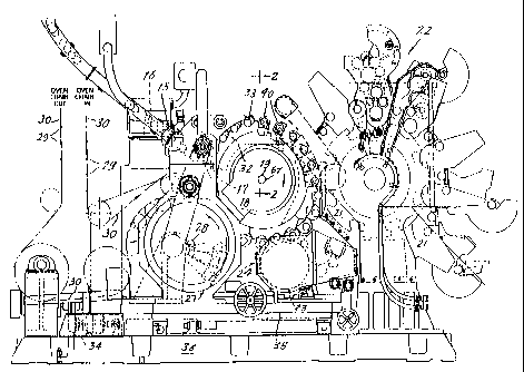
Fig. 1 is front elevation of the continuous motion can
decorating apparatus that includes a spindle disc assembly
constructed in accordance with teachings of the instant
invention.
Fig. 2 is a fragmentary cross-section of the spindle disc
assembly taken through line 2-2 of Fig. 1 looking in the
direction of arrows 2-2.
Fig. 3 is a view similar to Fig. 2 wherein, for the sake of
clarity, certain elements are removed and other element.s are
made more prominent.
Fig. 4 is an enlarged fragmentary front elevation of the
spindle disc assembly looking in the direction of arrows 4-4
CA 02294371 2008-08-11
- 4d -
of Fig. 2.
Fig. 5 is a front elevation of the spindle disc.
Figs. 6 and 7 are cross-sections taken through respective
lines 6-6 and 7-7 of Fig. 5 looking in the directions of the
respective arrows 6-6 and 7-7.
Fig. 8 is a fragmentary end view of the spindle disc
looking in the direction of the arrows 8-8 of Fig. S.
CA 02294371 1999-12-16
WO 98/57808 PCT/US98/11190
- 5 -
Fig. 9 is an exploded perspective of a spindle
assembly.
Fig. 10 is a front elevation of the spindle
assembly base looking in the direction of arrow 10 of
Fig. 9.
Fig. 11 is a cross-section taken through line
11-11 of Fig. 10 looking in the direction of arrows 11-
11.
Fig. 12 is an elevation looking in the
direction of arrows 12-12 of Fig. 11.
Fig. 13 is a side elevation which shows a size
comparison between the spindle assembly base of the
instant invention and that prior art base which is
replaced by the base of the instant invention.
Fig. 14 is a front elevation of the elements of
Fig. 13 looking in the direction of arrows 14, 14.
DETAILED DESCRIPTION OF THE INVENTION
Now referring to the Figures and more
particularly to Fig. 1 which illustrates continuous
motion cylindrical container decorating apparatus of the
general type described in the aforesaid U.S. Patent No.
3,766,851 and U.S. Patent No. 5,111,742. The apparatus
of Fig. 1 includes infeed conveyor chute 15 which
receives undecorated containers in the for of cans 16,
each open at one end thereof, from a supply (not shown)
and places cans 16 in arcuate cradles or pockets 17
formed by aligned depressions in the outer edges of
spaced rings 31, 32 (Fig. 2). The latter are fixedly
secured to disc-like spindle carrier 18 which is keyed to
horizontal drive shaft 19. A fixture comprising
concentric rings 45 and 64 spaced by angled standoffs 48
is interposed between pocket rings 31, 32 and carrier 18.
SUBSTITUTE SHEET (RULE 26)
CA 02294371 1999-12-16
WO 98/57808 PCT/US98/11190
- 6 -
Bolts 46 secure ring 45 against front surface 65 of
carrier 18 and bolts 47 mount pocket rings 31, 32 on ring
64. The latter is of larger diameter than ring 45 and is
positioned forward thereof.
Horizontally extending spindles or mandrels 20
(Fig. 2) are also mounted to carrier 18, with each
mandrel 20 being in spaced horizontal alignment with an
individual pocket 17 while passing through a short region
extending downstream from infeed conveyor 15. In this
short region, undecorated cans 16 are moved horizontally
rearward by a deflector (not shown), being transferred
from each cradle 17 to an individual mandrel 20. Suction
applied through an axial passage extending to the
outboard or front end 20a of mandrel or spindle 20 draws
container 16 rearward (to the left with respect to Fig.
2) to final seating position on spindle 20.
While mounted on mandrels 20, cans 16 are
decorated by being brought into engagement with
continuously rotating image transfer mat or blanket 21 of
the multicolored printing press decorating section
indicated generally by reference numeral 22. Thereafter,
and while mounted to mandrels 20, each decorated can 16
is coated with a protective film of varnish applied
thereto by engagement with the periphery of applicator
roll 23 in the overvarnish unit indicated generally by
numeral 24. Cans 16 with decorations and protective
coatings thereon are then transferred from spindles 20 to
suction cups (not shown) mounted near the periphery of
transfer wheel 27 while the latter rotates about shaft 28
as a center. Cans 16 carried by transfer wheel 27 are
deposited on generally horizontal pins 29 which project
from chain type output conveyor 30 that carries cans 16
through a curing oven (not shown).
SUBSTITUTE SHEET (RULE 26)
CA 02294371 1999-12-16
WO 98/57808 PCTIUS98/11190
- 7 -
By the time spindle 20 moves beyond the
downstream end of chute 15 and is in the proximity of
sensor 33, each spindle 20 should be properly loaded with
a can 16. If sensor 33 detects that a spindle 20 is
unloaded or is not properly loaded, then before this
particular spindle 20 enters the decorating zone wherein
printing blanket 21 normally engages can 16 on mandrel
20, this unloaded or misloaded spindle 20 is moved to a
tripped or "no-print" position. As a tripped mandrel 20
moves through the decorating zone it will be spaced from
the periphery of blanket 21. This no-print position is
achieved by controlling double acting cylinder 34 to trip
subframe 35 having spindle carrier shaft 19 mounted
thereon, by moving subframe 35 to the left with respect
to Fig. 1 while main base 36, to which printing unit 22
is mounted, remains stationary. Further, actuation of
sensor 33 causes overvarnish unit 24 to move downward
with respect to spindle carrying shaft 19 so that the
tripped spindles 20 do not engage overvarnish application
roll 23.
Spindle 20 is part of spindle subassembly 40
(Fig. 9) that also includes L-shaped base 41, stub shaft
44, two guide rods 51, 52 and two cam follower rollers
57, 58. In side elevation (see Figs. 11 and 13), base 41
includes horizontal main section 42 and arm 43 that
projects radially outward from main section 42, being at
the rear thereof and perpendicular thereto (Fig. 3).
Guide rods 51, 52 extend radially inward from main
section 42 being secured by respective bolts 54, 55 that
extend through apertures in plate 53 and are received by
threaded apertures 151, 152 at the radially outward ends
of respective rods 51, 52. Four bolts 56 extend through
holes in plate 53 and are threadably received by
SUBSTITUTE SHEET (RULE 26)
CA 02294371 1999-12-16
WO 98/57808 PCTNS98/11190
- 8 -
apertures 123 in base 41 to secure plate 53 against the
radially outward surface of main section 42. Retainer 59
at the rear o-f arm 43 secures spindle supporting shaft 44
so that it extends perpendicular to arm 43 in a position
radially outboard of main section 42 and overlying the
latter. Followers 57, 58 are rotatably mounted by
retainer 61 at the rear of main section 42, and ride in
closed loop cam track 62 that surrounds spindle disc
shaft 19. In a manner known to the art, cooperation of
cam 62 and followers 57, 58 controls the radial spacing
between the rotational axes defined by parallel shafts 19
and 44.
Figs. 5 and 6 illustrate naked spindle disc 18
that is provided with central aperture 66 which receives
drive shaft 19. Key 67 (Fig. 2) is received by slot 68
(Fig. 5) in the wall defining aperture 66 to provide
alignment, and the ringfeeder 144 provides a driving
connection and adjustment of runout between carrier shaft
19 and spindle disc 18. The latter mounts twenty-four
spindle subassemblies 40 as shown partially in Fig. 4,
there being equal angular spacings between the
subassemblies 40. Such spacings are established by a
pair of radial holes 73, 74 that extend inward from disc
periphery 81 and house respective cylindrical bushings
71, 72 (Fig. 2). Reciprocating guide rods 51, 52 extend
through bearing passages that are provided by the
respective bushings 71, 72. Extending forward from rear
surface 75 of carrier 18, and terminating short of front
surface 65, are twelve axial bores 76 each of which
communicates with one pair of holes 73, 74 that are at
the same angular position and a second pair of holes 73,
74 that are at an adjacent angular position. Thus, each
axial bore 76 intersects with four radial holes 73, 73,
SUBSTITUTE SHEET (RULE 26)
CA 02294371 1999-12-16
WO 98/57808 PCTNS98/11190
- 9 -
74, 74 at the radially inward ends of the latter. Small
cross-section circular slot 77 milled in rear surface 75
interconnects all twelve bores 76. The sizes and
locations of bores 76 and slot 77.are such that they do
not have a substantial effect on the strength of carrier
18. Thus, aluminum ring 78 (Fig. 3) held by bolts 79
functions only as a cover that retains grease within
bores 76 and slot 77. It is not necessary for cover ring
78 to be constructed of heavyweight material that will
reinforce the strength of the naked carrier 18.
Each bushing 71, 72 is retained in a respective
radial hole 73, 74 by an individual ring-like cap or
holder 80 (Fig. 3). Holders 80 are at the radially outer
ends of bushings 71, 72, and the radially inner ends of
bushings 71, 72 rest upon interior ledges of holes 73,
74. Each holder 80 contains two ring seals 82, 82 that
surround each guide rod 51, 52. Three bolts 83 that are
received by apertures 84 (Fig. 8) in carrier periphery 81
secure each holder 80 to carrier 18. Piloting the upper
ends of each bushing 71, 72 in annular undercut 99 at the
radially inner surface of holder 80 accurately positions
seals 82, 82 from beneath holder 80 relative to the
bearing passages provided by bushings 71, 72 to obtain
improved operation of guide rods 51, 52 as they
reciprocate in the bearing passages of.bushings 71, 72.
Each of the twenty-four apertures 86 (Fig. 5)
in the front surface of carrier 18 receives an individual
fitting 85 (Fig. 2). When this can decorating apparatus
is being set-up for operation, grease injected at fitting
85 travels a circuitous path to relief fitting 87 at
aperture 88 (Fig. 8) at carrier periphery 81. With
particular reference to Fig. 3, it is seen that this
circuitous path from fitting 85 to fitting 87 includes
SUBSTITUTE SHEET (RULE 26)
CA 02294371 1999-12-16
WO 98/57808 PCT/US98/11190
- 10 -
axial portion 91, annular cutout 92 inside of bushing 71,
axial portion 93, cutout 94 inside of bushing 72, axial
portion 95 and radial portion 96. The zig-zag slots 97
in the interior surfaces of bushings 71, 72 extend from
cutouts 92 and 94 toward both ends of bushings 71, 72.
Thus, when grease introduced at a fitting 85 appears at
its associated relief fitting 87 this is a positive sign
that both rods 51, 52 of a particular spindle subassembly
40 are lubricated.
As required, vacuum and pressure are supplied
to forward end 20a of mandrel 20 through an individual
flexible hose 101 having opposite ends clamped to
fittings 102, 103 that are connected, respectively, to
carrier 18 and spindle assembly 40. That is, straight
fitting 102 is screwed into an aperture of movable valve
element 104 that is secured by bolts 107 to the front
side of carrier 18, and L-shaped fitting 103 is screwed
into aperture 108 of base 41. Aperture 108 is at the
front end of main section 42 (see Figs. 9-14). Wear
?0 plate 106 secured to the front of movable valve member
104, is in sliding engagement with stationary valve
member 105 at interface 109. In a manner known to the
art, appropriate apertures in face valve members 104, 105
come into alignment at particular angular positions of
carrier 18 so that at appropriate times vacuum and
pressure levels that are delivered to the input side of
stationary valve member 105 (side remote from valve
member 104) extend through valve members 104, 105 to
appear at mandrel assembly 40.
To extend the life of hose 101, fittings 102,
103 do not have parts that are free to swivel or
otherwise move relative to each other once fitting 103 is
secured to mandrel subassembly 40 and fitting 102 is
SUBSTITUTE SHEET (RULE 26)
CA 02294371 1999-12-16
WO 98/57808 PCT/US98/11190
- 11 -
secured to movable valve member 104. Further, hose 101
contains a complete relatively large diameter loop, and
fittings 102, 103 are angularly offset so that hose 101
will not rub against itself as fitting 103 reciprocates
radially. In addition, hose 101 is positioned so that it
will not rub against other elements.
Main section 42 of base 41 is provided with
axial passage 110 that extends rearward from aperture 108
to the radially inner end of passage 111 in arm 43.
Passage 112 extends to the radially outward edge of arm
43 where theradially outward end 109 of passage 111 is
plugged. Elongated opening 112 at a midpoint of passage
111 connects with arm aperture 113 which houses the rear
end of mandrel shaft 44. Passages (not shown) extend
from aperture 113 to connect with front end 20a of
mandrel 20. Arm 43 is also provided with diagonal
passage 114 that extends to recess 116 wherein one end of
stub shaft 61 (Fig. 2) is positioned. To lubricate cam
follower rollers 57, 58, grease is introduced to passage
114 at its radially outer end 117. Guide rods 51, 52
pass through apertures 121, 122 that extend radially
through main section 42, and four apertures 123 in the
radially outer surface of main section 42 receive bolts
56 that secure guide rod holding plate 53 to base 41.
Base 41 weighs considerably less than prior art
base 119 shown by the phantom outline in Figs. 13 and 14,
and other mandrel support bases that can be replaced by
base 41. That is, base 41 does not include the sections
between the solid line and phantom outline in Figs. 13
and 14, whereas prior art base 119 includes those
sections plus substantially the entire base 41. It is
noted that for base 41, resistance to bending between arm
43 and main section 42 is maintained at a satisfactory
SUBSTiTUTE SHEET (RULE 26)
CA 02294371 1999-12-16
WO 98/57808 PCT/US98/11190
- 12 -
level by thin triangular gussets 126 (Fig. 9) which
provide reinforcement at each side of arm 43 where it
joins main section 42.
Not only is base 41 light in weight, but main
section 42 is relatively thin so that the rotational axis
of mandrel 20, located at center A (Fig. 2) of
cantilevered shaft 44 can be relatively close to the
radially outward ends of bushings 71, 72. This serves to
reduce the bending moments that act upon guide shafts 51,
52 and translate into bending forces that cause rapid
wear of bushings 71, 72 in prior art constructions.
In a practical embodiment of apparatus
constructed according to the instant invention for
decorating two piece cans, where mandrel 20 has an
approximate diameter of 2.6 inches, the radially measured
spacing between rotational axis A for mandrel 20 and the
radially outer ends of bushings 71, 72 is as little as
5.2 inches, with cam slot 62 being shaped and positioned
so that for each revolution of mandrel carrier 18 axis A
travels through a radial stroke of 3 inches.
Although the present invention has been
described in relation to particular embodiments thereof,
many other variations and modifications and other uses
will become apparent to those skilled in the art. It is
preferred, therefore, that the present invention be
limited not by the specific disclosure herein, but only
by the appended claims.
SUBSTITUTE SHEET (RULE 26)