Note : Les descriptions sont présentées dans la langue officielle dans laquelle elles ont été soumises.
CA 02294965 1999-12-22
WO 99/00320 PCT/AU98/00487
1.
BEVERAGE DISPENSEF:
The present invention relates t~,~ improvements in or relating to dispensers,
and more
particularly hut not e~;clusively to improvements to dispensers for beverages
such as
S wafer.
BACKGROUND OF 'If HE INVENTION
Dispensing units for beverages such as spring water are becoming increasingly
popular,
particularly in areas where the quality of mains water is questionahte or is
simply
unpalatable.
A typical dispenser unit for spring water currently in widespread use
comprises <t
refrigerated sump on v~rhich a large transparent plastic bottle is mounted.
Mounting the
bottle on the unit generally involves removing the seal from the bottle, and
lilting the
bottle to approximatel~~ waist height while inverting the bottle whereupon the
inverted
bottle is mounted on the unit with the neck of the bottle extending into the
sump.
In this arrangement, the bottles are heavy, being generally approximately 18
kilograms,
and cumbersome. The requirement to lilt the bottle to at least waist height
whilst
inverting it is potentially injurious as it places particular strain on the
back and arms. It is
noted that occupational health and safety guidelines specify a maximum weight
limit of 16
kilograms which can be: safely lifted by females, leading to a potentially
unsafe situation in
instances where females are required to replace the bottles on the dispenser.
In addition, spillage of bottle contents more often than not occurs from the
open neck of
the bottle during inversion of the: bottle for placement on the dispenser.
Furthermore, with units of this type the only part of the unit refrigerated is
the sump,
which contains only a relatively small volume of water at a given time. As the
water
bottles are stored at groom temperature, significant volumes of chilled water
are not
continuously available. This can he particularly disadvantageous in warm
climates or in
periods of hot weather when large volumes of chilled beverage are required for
refreshment.
CA 02294965 1999-12-22
WO 99/00320 PCT/AU98/00487
2.
In addition, the size and shape of the bottles is such that they cannot be
stacked with any
safety and hence a significant amount of storage space is required, as the
bottles are
normally delivered in bulk rather than on an individual basis.
Accordingly, in an office environment or indeed in any other environment, a
large amount
of floor space is required to store the bottles. This can be particularly
unsightly in cases
where i7oor space is limited or when the bottles cannot he stored out of
sight.
It has also been observed that water contained in transparent plastic bottles
of this type
tends to oxidise during use and may he exposed to light during storage,
leading to the
potential generation of free radicals which can he potentially injurious to
health if
ingested.
It has further been observed that following use the bottles are generally
cleaned using
chemicals. This leads to the possihility that chemical residues may be left on
the inner
walls of the bottle despite rinsing. It will he appreciated that any chemical
residue may be
taken into solution in the beverage when the bottle is refilled and
accordingly may be
ingested when the beverage is eventually dispensed. The ingestion of such
chemical
residues is potentially injurious to health.
It has also been observed that sludge build-up in the sump and/or around the
dispensing
outlet can be a particular problem with units of the type descrihed. If the
dispensing outlet
is not cleaned on a regular basis, the risk of contamination of beverage to be
dispensed by
bacteria in the sludge is likely to increase.
SUMMARY OF THE INVENTION
The present invention accordingly provides in one embodiment a dispenser unit
for
beverages, the dispenser unit including:-
a housing for receiving a bladder containing a beverage, the bladder having
outlet
means for dispensing the beverage; and
the housing being a~-operable with holding means for releasahly holding the
outlet
means relative to the housing when dispensing the beverage.
CA 02294965 1999-12-22
WO 99/00320 PCT/AU98/00487
3.
The present invention provides in another embodiment a beverage dispenser, the
dispenser
including:-
a housing;
a bladder containing a beverage, the bladder being mounted in the housing and
having outlet means for dispensing the beverage wherein the dispenser includes
holding means co-operable with the housing for reicasahly holding the outlet
means
relative to the housing when dispensing a beverage.
A dispenser unit or beverage dispenser according to the present invention
preferably
includes a refrigerated housing.
A beverage for dispensing according to the invention may be water, such as
distilled
water, spring water on filtered water. It may be a fruit juice, or milk. In a
particularly
preferred embodiment, spring water is made available for dispensing from a
dispenser
according to the present invention. Other beverages for dispensing are also
envisaged
within the scope of the present invention.
A housing according to the irmention may take any suitable form. The shape of
the
housing may be comylementar_y to the shape of a bladder to be received
therein. The
housing preferably foams a cavity for receiving a bladder according to the
invention. The
housing may substantially enclose the bladder.
In one preferred embodiment the outlet means projects from the housing to
facilitate
beverage dispensing but the housing otherwise fully encloses the bladder
whereby to form
a closed compartment for the bladder.
The housing may accordingly include a compartment whereby the bladder is
received in
the cavity defined by vralls of the compartment. The compartment may be
separable from
the housing. The co~mpartmervt may accordingly be in the form of an insert.
The
arrangement may be such that the compartment is releasahly receivable in the
housing.
The compartment may be in the form of a box. The compartment and the housing
may
carry a~mplementary i.nterengaging members whereby the compartment can be
releasahly
located in the housing.
CA 02294965 1999-12-22
WO 99/00320 PCT/AU98/0048'7
4.
A housing according to the invention may include a sloping floor. The
arrangement may
be such that the floor assists in directing contents of the Madder towards the
outlet means.
In one embodiment, the floor is arranged so as to slope towards the dispensing
point of
the dispenser whereby when the bladder is placed in the housing the contents
of the
bladder are urged towards the dispensing point. A compartment according to the
invention may carry the sloping floor.
A housing according to the invention may include an openahle lid. The lid may
he hinged
to the housing in known manner.
A housing according to the invention may he insulated whereby the temperature
of the
bladder contents may be controlled. The housing may include inner and outer
walls
between which is sandwiched insulating material. Polystyrene, polyurethane and
other
suitable insulating materials are well Known. The insulating material may be
part of a
separable compartment according to the invention.
The housing may be formed from any suitable material. Suitable materials
include plastics
materials, including mouldable plastics materials.
Other housing shapes, constructions and arrangements are envisaged within the
scope of
the present invention.
A bladder according to the invention is preferably collapsible. The
arrangement is
preferably such that the walls) of the bladder is/are collapsible in response
to egress of
contents of the bladder from the bladder.
A bladder according to the invention may be in the form of a hag in which the
beverage is
receivable. The bag is preferably sealable to prevent contents of the bag from
escaping
when placed in the bag. A bag made in the style of a liner for a wine cask may
he
suitably employed as a bladder according to the invention.
The bladder is preferably formed from a material suitable for hygienic contact
with fluids
for human consumption. The arrangement is preferably such that the bladder and
hence
the contents thereof is held under vacuum for dispensing.
A bladder according to the invention is preferably constructed and arranged so
as to
prevent the contents of the bladder from coming into contact with light during
storage.
CA 02294965 1999-12-22
WO 99/00320 PCT/AU98/00487
5.
Examples of materials suitable for use as a bladder according to invention
include
metallised, laminate or mufti-layer films.
The bladder may he disposahlle or recyclable. Where the bladder is in the form
of a
laminated or mufti-layer plastica material the bladder may be made available
for recycling
or easily discarded in a waste bin.
Outlet means for a bladder according to the present invention may be capable
of
facilitating the filling ;and dispensing of the contents of the bladder. The
outlet means is
preferably attached to the hladdler. In particularly preferred embodiment the
outlet means
is integrally formed with or welded to the bladder. The outlet means may he in
the form
of a two-component valve. One component may comprise a spout which is
integrally
formed in a wall of the bladder. The second component may comprise a valve,
tap or
spigot. The valve, talc or spigot may be adapted to form a snap fit connection
over the
sp«ut after the bladder is filled through the spout whereby to form the
assembled two-
component outlet means. Where the contents of the bladder is under vacuum, the
outlet
means is preferably arranged to resist ingress of air into the bladder on
opening the valve,
tap or spigot which would lessen or destroy the vacuum inside the bladder. The
valve, tap
or spigot may accordin>>ly act as a one-way valve.
Outlet means suitable fur use in accordance with the present invention may he
those as are
already known and used in wine casks.
The holding means according to the present invention is co-operable with the
housing
preferably to hold the outlet means relative to the dispenser. The holding
means may he
constructed and arranged so as t~o be movable relative to the housing. The
holding means
may he movable relative to the housing between a loading position and a
dispensing
position. In the dispensing position the holding means and the housing may co-
operate to
form an aperture, the ~autlet means being held in a position suitable for
dispensing the
beverage from the bladder in which the outlet means projects at least
partially through the
aperture.
In the loading position the aperture may be opened sufficiently to allow the
outlet means
and hence the bladder to be removed from the housing and replaced. The holding
means
CA 02294965 1999-12-22
WO 99/00320 PCT/AU98/00487
6.
may be separated from the housing in the loading position. In an alternative
arrangement
within the scope of the present invention the holding means is movable
relative to the
housing to enlarge the aperture sufficiently to release the outlet means and
hence allow the
bladder to he replaced when the holding means is moved to the loading
position.
Most preferably, the holding means is slidahle relative to the housing. The
holding means
may be releasably slidable in guides provided on the housing. In one preferred
arrangement the holding means is slidable in a substantially vertical
direction 'in a pair of
opposed guides arranged on either side of a housing aperture according to the
invention.
In this embodiment the holding means is passed along the guides in a
substantially vertical
direction whereby it co-operates with the housing to releasably hold the
outlet means for
the bladder received in the housing aperture.
The holding means may comprise a holding member. The holding member may be
elongated. The holding member may he substantially planar. In one preferred
embodiment the holding means comprises an elongated substantially planar
member
movable relative to the housing. The holding member preferably includes
engaging means
for engaging part of the outlet means. The engaging means may comprise a
tongue
engageable with the outlet means. In another embodiment, the engaging means
comprises
a recess engageable with the outlet means. Other constructions and
arrangements are also
envisaged within the scope of the invention.
The holding means may include indication means for providing a visual
indication of the
current level of the contents of the bladder. In one embodiment the indication
means
c«mprises level indication means. In this embodiment the level indication
means
comprises a transparent window whereby visual observation through the window
provides
an indication of the current level of the bladder contents. The indication
means may
include graduations to assist in determining the current level of the bladder
contents.
In one particularly preferred embodiment according to the present invention
the holding
means comprises an elongated member having a recessed end, the arrangement
being such
that when the holding means is mounted on the housing the recess contacts a
corresponding part of outlet means for the bladder and holds the outlet means
relative to
the dispenser housing, the elongated member being transparent substantially
throughout its
length and having a plurality of graduations marked thereon.
CA 02294965 1999-12-22
WO 99/00320 PCT/AU98/00487
7.
A dispenser according to tht; invention may include means for monitoring
and/or
controlling the temperature of the cavity into which the bladder is received.
Temperature
monitoring means according to the present invention may comprise a probe. The
probe
may be held within a.n insulating member of the housing. Temperature control
means
S according to the invention may comprise a thermostat as is generally known
in the art.
A dispenser unit according to the present invention may include refrigeration
means. The
refrigeration means may be capable of refrigerating the contents of the
bladder. In one
embodiment, the refrigeration means is disposed externally to the rear of the
housing.
The refrigeration means may extend at least partly underneath the housing
cavity for
receiving a bladder according to the invention whereby the whole of the
contents of the
bladder may be refrigerated. In a preferred embodiment the housing includes a
metal
panel. The panel may comprise or form part of the sloping floor. The panel may
be
cooled by the refriger;ition means. The panel may be in direct contact with
the bladder
whereby cooling of thc; panel by the refrigeration means effects cooling of
the bladder and
its contents.
A dispenser unit according to the invention may he constructed and arranged
whereby it
can be placed on a shelf in a refrigerator whereby a ready source of distilled
water or
filtered water can be made available in a domestic environment.
A dispenser unit according to the present invention may include at least one
cup dispenser.
The cup dispenser may he mounted on an external wall of the dispenser housing
in known
manner. In a particularly preferred embodiment, a pair of cup dispensers are
mounted on
opposed walls of the housing.
A dispenser unit according to the invention may include a water tray and a
water tray grid
as is known in the art. The waver tray and grid may be positioned below the
dispensing
point of the dispensing unit.
BRIEF DESCRIPTION OF PREFERRED EMBODIMENT
The present invention will now be described with reference to particularly
preferred
embodiments, in which:
Figure 1 is a side elevation of a dispenser unit in accordance with one
embodiment
of the present invention;
CA 02294965 1999-12-22
WO 99/00320 PCT/AU98/00487
8.
Figure 2 is a front elevation of the dispenser unit of Figure 1;
Figure 3 is an exploded perspective view of a dispenser unit in accordance
with
one embodiment of the present invention;
Figure 4 is an exploded perspective view of part of a dispenser unit in
accordance
with one embodiment of the present invention.
Figure 5 is a perspective view of an alternative form of holding member;
Figure 6 shows partial elevational views of the holding member of Figure 5
inserted in the aperture in open and closed configurations;
Figure 7 is a plan view of the partial Section B of Figure 6;
Figure 8 is a plan view of the partial Section A-A of Figure 6; and
Figure 9 is a partial elcvational view of the Section Z through Figure 8.
For convenience, in the drawings of Figures 1 to 4 like integers have been
accorded like
reference numerals. The same applies to Figures 5 to 9.
Turning to the drawings, Figure 1 shows generally a dispenser 10 for
dispensing
beverages, which in the embodiment shown incorporates refrigeration means 36.
It will
be appreciated that dispenser units according to the present invention may he
provided
without refrigeration means without departing from the inventive concept
disclosed herein.
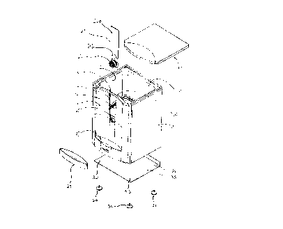
Dispenser 10 includes a housing 11 having a walled compartment 12 defining a
mvity 15
for receiving a bladder for beverages (not shown). Housing 11 incorporates a
base 35
securable to housing 11 via scouring means 29, 30, 31 passed through apertures
32, 33, 34
in base 35.
In the embodiment shown, compartment 12 includes a sloping floor 14. It wilt
he noted
that floor 14 slopes towards the dispensing region of dispenser 10 whereby to
assist the
flow of bladder contents to the dispensing point in the region of outlet means
22 for the
bladder.
CA 02294965 1999-12-22
WO 99/00320 PCT/AU98/00487
9.
Dispenser 10 includes an opc,nahle lid 13 which with housing 11 forms a closed
compartment 12 to receive the bladder.
Elongated aperture 16 is arranged on a front face 17 of housing 11. As can he
seen from
Figure 3, aperture 16 tapers tov~~ards cradle 20 in which outlet means 22 for
the bladder is
receivable such as by seating in cradle 20. Aperture 16 incorporates opposed
guides 18,
19 in which holding ntemher 21 is slidahly receivable. Holding member 21
includes an
elongate body member 21a andl an arcuate recess 21h arranged at a lower edge
thereof.
Recess 21h is capable of engaging a corresponding part of outlet means 22 for
the bladder
whereby on seating outlet meams 22 in cradle 20 holding member 21 is inserted
into
guides 18, 19 and slidahly moved to bring recess 21h into contact with a
corresponding
portion of outlet means 22. In this way, a bladder may he readily held in
cavity 15 and
releasahly secured to the housing ll via the co-operahly interengaging
arrangement of
holding member 21 with outlet means 22 seating in cradle 20.
In the embodiment shown in I' figure 4, compartment 12 is in the form of an
insert 12
comprising a box which is removable from housing 11. Box 12 carries in a front
face 44
thereof an aperture 39 including opposed guides 18, 19 in which holding member
21 is
receivable. It will be rooted chat the opposed guides of aperture 39 are in
the embodiment
shown substantially parallel.
Aperture 39 terminates in a cradle 40 whereby to provide a further support for
outlet
means 22 received in cradle 20 of housing 11.
Insert 12 includes engaging mc;mhers 41, 42 to intercngage with corresponding
recesses
43, 44 of housing 11 whereby to form a substantially rigid unit when
assembled. Lip 45
extending around the upper periphery of compartment 12 enables compartment 12
to rest
an a corresponding upper edge of housing 11.
In use a bladder filled with a fluid such as water under vacuum is placed in
cavity 15 of
compartment 12 and outlet means 22 seated in cradle 20 of housing 11. Holding
member
21 is received in opf~osed guides 18, 19 and slidahly moved towards outlet
means 22
seated in cradle 20 w~herehy recess 21h carried by holding member 21 engages
with a
corresponding portion of outlet means 22 and is thereby secured relative to
housing 11.
CA 02294965 1999-12-22
WO 99/00320 PCT/AU98/00487
10.
The beverage may now he dispensed by taking a cup 25 from cup dispenser 23,
placing it
on the grid (not shown) of water tray 28 received in water tray housing 27 and
opening
outlet means 22 to dispense the required quantity of beverage.
Exhausted bladders may be easily replaced by reversing the procedure described
whereby
to release the outlet means 22 and remove the bladder from cavity 15.
The present invention has the advantage that bladders may be easily inserted
into and
replaced in dispenser units according to the present invention. Furthermore,
dispenser
units according to the present invention are able to dispense beverages in the
hygienic
manner not previously obtainable with dispensers of the present art. Moreover
the filled
bladders may be stored in boxes which can he more conveniently stacked than
the prior
art bottles.
In the embodiment shown in Figures 5 to 9, a particularly preferred form of
holding
member 50 is shown for use in the housing 49. It forms an aperture 48 with the
arcuate
wall of the housing 73 to hold the outlet means 79.
The holding member 50 is formed from a transparent moldable plastic material
in order
that a user may be able to look through the holding member into the housing to
determine
the state of fill of the bladder contained therein.
The holding member is formed with a flat elongate body portion 51. The lower
portion of
the holding member is formed with an arcuate recess 52 which is adapted to fit
part of the
way around the tubular spout 80 of the outlet means in the matter illustrated
best in
Figure 9.
A curved lip 53 is provided at the top of the holding member to give a user
purchase on
the holding member. Thus the user may slide the holding member up and down in
the
guide channels 70. The guide channels are formed on either side of the
elongate aperture
48 as an edge of the housing wall 71 surrounding this region.
Integral resilient legs 58 extend from the upper part of both sides of the
holding member,
the legs being formed with a ramped extension 59. Each resilient leg with
ramped
extension is arranged to abut against a ledge 57 provided in the guide
channels in order to
hold the holding member in the elevated position shown on the left hand side
of the
CA 02294965 1999-12-22
WO 99/00320 PCT/AU98/00487
11.
Figure 6. This facilitates insertion of the dispenser into the aperture 48
after which the
holding member 50 may be pushed downward to lock the dispenser in place when
the
holding means reaches the position shown on the right side of the drawing
shown in
Figure 6. It is noted that the ledge 57 and the bottom of the ramped extension
59 are
angled so that the ramped extension will be pushed inwardly when sufficient
downward
pressure is applied to the top of the holding member thereby allowing the
holding member
to slide past the ledge :i7.
The holding member also includes two integral resilient elements 60. These are
also in
the form of legs each being provided with a catch member 61 which is adapted
to catch
under the abutment 66 provided in the guide channel. This construction limits
the upward
travel of the holding member in the guide channel and thus prevents it
becoming separated
from the channels. Integral fins 65 extending along the length of each of the
vertical sides
of the holding member are also provided to assist with tracking of the holding
member in
the guide channels provided on either side.
The outlet means 79 v~~hich includes the tubular spout 80 and a deformable
spigot 90 snap
fitted on the end there;~f is held securely in the aperture of the housing.
This is by virtue
of the fact that the holding me.mher fits into a channel formed between the
two annular
reinforcing ribs 82 and 83 formed on the tubular spout. Similarly, the arcuate
housing
wall also fits into the same channel.
An annular flange 81 is provided on the end of the tubular spout and provides
a surface
whereby the spout may be heat sealed or welded to a bladder (not shown).
ZS
The walls of the housing may be hollow to accommodate filling with insulation
72 and
also to reduce weight.
The dispenser is operated simply by manipulation of the toggle 91 provided on
the spigot
to dispense content from the bladder held in the housing.
While it has been convenient to describe the invention in relation to
particularly preferred
embodiments, it is to be appreciated that other constructions and arrangements
are
considered as falling ~~ithin the scope of the invention. Various
modifications, alterations,
variations, and/or additions to the constructions and arrangements herein are
also
considered as falling within the scope and ambit of the present invention.