Note : Les descriptions sont présentées dans la langue officielle dans laquelle elles ont été soumises.
CA 02296341 2000-O1-17
WO 99/03589 PCT/US98/14852
--PULVERIZING MATERIALS INTO SMALL PARTICLES--
Backctround of the Invention
The invention relates to apparatus and methods of
pulverizing materials into small particle sizes.
Reducing large, discrete materials into smaller
particles is an important process for many industries.
For example, in the mining industry, ores are crushed
into smaller size particles to increase the available
surface area so that metals can be extracted by chemical
leaching. The cement industry grinds rocks into grains
of various particle sizes. Most machines used for these
purposes grind larger chunks of material into smaller
particles with rollers or with a ball crusher. The
crushed material is typically comprised of a range of
particle sizes. Both types of machinery are massive and
prone to breakdown when crushing hard materials. In
addition, they have large power requirements.
The recycling industry also reduces waste
materials into smaller particles. Typically, materials
with different compositions must be separated prior to
being reduced in size, making the process more costly.
The livestock industry produces a great deal of
animal waste that must be dried and reduced in bacterial
content, which process can takes weeks, before being used
for fertilizer or other purposes.
Summary of the Invention
According to one aspect, the invention provides a
rotor for an apparatus for pulverizing material comprised
of wet or dry discrete objects into relatively smaller
particles. The rotor includes a hub being adapted for
coupling to a rotatable shaft for rotation therewith, and
a rotor plate that is centrally coupled to the hub. The
rotor plate has an approximately polygonal-shaped
CA 02296341 2000-O1-17
WO 99/03589 PCT/US98/14852
- 2 -
peripheral edge forming a plurality of apices. A
plurality of vanes are positioned on a side of the rotor
plate, wherein each of the vanes extends approximately
radially inward from one of the apices. The rotor plate
preferably has an odd number of sides, for example, the
peripheral edge can have a shape being a member of the
group consisting of a pentagon, a heptagon and a nonagon.
Each of the vanes can be positioned to provide a
small overhang over the peripheral edge of the rotor
plate, and positioned with respect to an apex of the
rotor plate such that a leading surface of the vane,
defined with respect to a direction of rotation, is at
the apex. An end of each of the vanes being located near
an apical corner can be shaped like the peripheral edge
at that location. Each of the vanes can be curved in an
arc, the concave side facing the direction for rotation.
Each of the vanes can have an upper edge that is beveled
such that the elevation of the upper edge generally
increases with increasing distance from the hub. One
type of rotor, a distributor rotor, can further include a
ring fixed to the upper edges of the vanes, the ring
having a regular polygonal shape being about aligned with
the peripheral edge of the rotor plate.
The pulverizing apparatus, which can having at
least one rotor as described above, can further include a
housing having first and second ends, the first end
including input structure being adapted to introduce the
material into the housing, the second end including
output structure adapted to remove the smaller particles.
A rotatable shaft extends longitudinally through the
housing between the first and second ends. The hub of
each rotor is coupled to the shaft for rotation
therewith. The housing can have longitudinally extending
internal sides that form longitudinally extending
CA 02296341 2000-O1-17
WO 99/03589 PCT/US98/14852
- 3 -
interior corners where they meet. There may be an odd
number of internal sides, for example, the sides can form
a regular nonagon in lateral cross section.
The apparatus can further include an orifice plate
positioned between each adjacently located pair of the
rotors, each orifice plate extending inwardly from the
internal sides of the housing to a central aperture which
provides an orifice around the shaft. The orifices of at
least two of the orifice plates can be of different
sizes.
In one configuration, the central aperture of each
orifice plate has a diameter that is smaller than a
circle defined by the locus of the apices of the rotor
located immediately upstream from the orifice plate, the
upstream direction being determined by a direction of
movement of the material through the housing. In another
configuration, the orifices generally increase in size
with increasing distance from one of the first and second
ends of the housing.
The apparatus can also include a plurality of
circumferentially spaced members located proximate each
of the rotors, wherein the members extend inwardly from
the corners of the housing toward the rotors. The
members can be configured as pins, which can be arranged
to provide support to the orifice plates.
In a particular embodiment, the locus of the
apices of each rotor defines a circle, and the circles
generally increase in size with increasing distance from
one of the first and second ends of the housing.
The distance between each orifice plate and the
rotor positioned next nearest the first end of the
housing defines a first spacing, the distance between
each orifice plate and the rotor positioned next nearest
the second end of the housing defines a second spacing,
the distance between each pair of adjacently located
CA 02296341 2000-O1-17
WO 99/03589 PCT/US98/14852
- 4 -
orifice plates defines a third spacing, and the distance
between each pair of adjacently located rotors defines a
fourth spacing. In some embodiments, at least one of the
first spacing, the second spacing, the third spacing, and
the fourth spacing is non-uniform. One or more of the
first spacing, the second spacing, the third spacing and
the fourth spacing can be generally decreasing with
increasing distance from the first end of the housing,
and the orifices can be generally increasing in sizewith
increasing distance from the first end of the housing.
In another aspect, the invention provides an
apparatus for pulverizing material comprised of wet or
dry discrete objects into relatively smaller particles.
the apparatus includes a housing having a longitudinal
central axis, the housing including a first end
comprising input structure being adapted to introduce the
material into the housing, a second end comprising output
structure adapted to remove the smaller particles, and a
longitudinally extending internal surface surrounding the
central axis, the internal surface having sides meeting
in longitudinally extending corners. A rotatable shaft
extends substantially coextensively with the central
axis. At least one rotor is positioned the housing and
coupled to the shaft. Each rotor includes a hub being
coupled to the shaft for rotation therewith in a plane
transverse to the central axis, a rotor plate centrally
fixed to the hub, and a plurality of vanes on a side of
the rotor plate, each of the vanes extending about
radially inward from a peripheral edge of the rotor
plate. In one feature, orifice plates are positioned
alternately with rotors, an orifice plate being arranged
between each pair of adjacently located rotors. Each
orifice plate extends inwardly from the internal side
surfaces of the housing to a central aperture which
provides an orifice around the shaft, the orifices being
CA 02296341 2000-O1-17
WO 99/03589 PCT/US98/14852
- 5 -
of more than one size. In another feature, a plurality
of circumferentially spaced members are located proximate
' the at least one rotor, wherein the members extend
inwardly from the side surface towards the at least one
rotor. In yet another feature, the distance between each
orifice plate and the rotor positioned next nearest the
first end of the housing defines a first spacing, the
distance between each orifice plate and the rotor
positioned next nearest the second end of the housing
defines a second spacing, the distance between each pair
of adjacently located orifice plates defines a third
spacing, and the distance between each pair of adjacently
located rotors defines a fourth spacing. At least one of
the first spacing, the second spacing, the third spacing
and the fourth spacing is non-uniform.
In yet another aspect of the pulverizing apparatus
of the invention, the housing defines a longitudinal
central axis and includes a first plate at a first end, a
second plate at a second end, the second plate including
an opening through which the smaller sized particles exit
the housing, and longitudinally extending internal sides
having a substantially polygonal-shaped lateral cross-
section, the sides meeting in longitudinally extending
corners. A rotatable shaft extends substantially
coextensively with the central axis. A feed chute
extends through an opening in the first plate, the feed
chute being adapted for introducing the material into the
housing. A plurality of rotors are longitudinally spaced
apart within the housing. Each rotor includes a hub
being centrally coupled to the shaft for rotation
therewith, a rotor plate being centrally fixed to the
hub, the rotor plate having an approximately polygonal-
shaped peripheral edge having apices, and a plurality of
vanes on a side of the rotor plate being closest to the
first end of the housing, each of the vanes extending
CA 02296341 2000-O1-17
WO 99/03589 PCT/US98/14852
- 6 -
approximately radially inward from one of the apices. A
first rotor being a distributor rotor is positioned
closest to the first plate such that material introduced
into the housing through the feed chute is directed
toward the distributor rotor. An orifice plate is
positioned between each pair of adjacently located
rotors. Each orifice plate extends inwardly from the
internal sides of the housing to a central aperture which
provides an orifice around the shaft. A plurality of
members are positioned in the longitudinally extending
corners and project radially inward therefrom, each
member being located near a rotor.
Other features can be included in any of the
pulverizing apparatus described above. A mechanism, such
as a variable speed motor, can be coupled to the shaft
for rotating the shaft at a rotational speed of at least
600 rpm. The apparatus can include an additional input
structure adapted to introduce a substance through the
top plate into the housing, the input structure being
separate from the feed chute. The additional input
structure can advantageously include a regulator
mechanism configured to regulate a flow of a gas or a
liquid into the housing. The pulverizing apparatus can
further include a heat exchanger on an outside wall of
the housing configured to provide or remove heat from the
housing.
The invention also provides a method of
pulverizing a material comprised of wet or dry discrete
objects into relatively smaller particles. The method
includes: providing a pulverizing apparatus that includes
a housing, a rotatable shaft extending through the
housing between first and second ends thereof, rotors
coupled to the shaft for rotation therewith, a stationary
orifice plate located between each adjacent pair of the
rotors, each orifice plate being provided with a central
CA 02296341 2000-O1-17
WO 99/03589 PCT/US98/14852
aperture surrounding the shaft; rotating the rotors to
cause an air flow through the housing in an alternatingly
radially outward and radially inward flow path around the
rotors and through the apertures; introducing the
material into the first end of the housing; causing a
substantial portion of the material to flow with the air
flow; causing shock waves in the flowing material and air
flow with the rotation of the rotors; and pulverizing the
flowing material with the shock waves.
One or more other features may be included in the
method. Causing a substantial portion of the material to
flow with the air flow can include flowing the material
at a speed sufficient to maintain a Coanda effect in the
material flowing around the rotors and through the
orifices. Providing a pulverizing apparatus can include
providing each rotor with a substantially polygonal-
shaped rotor plate having apices that are located on an
imaginary circle, and vanes on a side of the rotor that
extend approximately radially inward from the apices
toward the shaft. Providing a pulverizing apparatus can
include providing the housing with internal sides that
meet in longitudinally extending corners. Providing a
pulverizing apparatus can include arranging the rotors,
the orifice plates and the housing to maintain a negative
back pressure in the flowing material as it flows through
each of the apertures. The method may further include
regulating the air flow through the housing. It may
include introducing a process material into the housing
while introducing the first mentioned material into the
housing, causing the process material to commingle with
the first mentioned material.
A pulverizer apparatus according to the present
invention can be employed for a variety of uses. For
example, the pulverizer apparatus of the invention can be
configured to pulverize rocks, including ores containing
CA 02296341 2000-O1-17
WO 99/03589 PCT/US98/14852
_ g _
precious and/or semi-precious-metal, into a fine powder.
In some ores, particles of elemental components that do
not easily alloy, such as gold, can be liberated from
other components. Gangue material is often separated
from the ore. Clays can be pulverized into fine powders
for ceramic uses. The pulverizing is done with a minimal
expenditure of energy and minimal wear on the pulverizer.
The pulverizer can be arranged to pulverize
discard tires into small particles of rubber, with the
corded fabric and steel belt components substantially
separated from the rubber.
The pulverizer can be arranged to pulverize whole,
unwashed aluminum beverage cans into small sized, dry
particles for recycling.
The pulverizer can be arranged to pulverize
bottles for recycling. The pulverizer liberates other
debris that may be mixed with the bottles, such as, for
example, metal caps, rubber seals, metal foil and paper.
Liquid remains are completely removed. Different colored
glasses can be separated by adjusting the rotational
speed of the rotor assembly.
The pulverizer can be arranged for rapidly
reducing an organic sludge or animal waste, such as, for
example, manure, to a dry powder with a significantly
reduced bacterial content.
The pulverizer may also be arranged to grind
grains, pharmaceuticals, or most any non-metallic
material into a powder. The size of the powder grains
can be adjusted by adjusting the speed of rotation, the
number of rotor and orifice plate stages, and the number
of sides of the rotors.
The pulverizer can be arranged as an air scrubber,
for example, in a smoke stack to change the chemical and
size characteristics of the stack discharge.
CA 02296341 2000-O1-17
WO 99/03589 PCT/US98/14852
- 9 -
The pulverizer can be arranged to pulverize
ceramic components of catalytic converters, by which
precious metals are conglomerated into panable particles.
The pulverizer can be configured to provide a
regulated fluid input, through which a regulated amount
of a gas or liquid can be added to the material being
pulverized. The gas can be additional air for enhancing
and regulating the flow of material through the
pulverizer. The gas or liquid can be a reaction
producing material to enhance a chemical transformation
of the material being pulverized, or a reaction slowing
or stopping material to inhibit a chemical transformation
of the material being pulverized.
These and other advantages of the invention will
become apparent from the following description of
specific embodiments when read in conjunction with the
appended drawings.
Brief Description of the Drawing
Specific embodiments of the invention will now be
described with reference to the drawings, in which:
FIG. 1 is an elevation view of a pulverizer system
according to the invention;
FIG. 2 is a top plan view of the pulverizer system
illustrated in FIG. 1.
FIG. 3 is an elevation view of a rotor assembly
housing of the pulverizer system illustrated in FIG 1;
FIG. 4 is a cross sectional view through line 4-4
of FIG. 3, and in which a distributor rotor is shown in
plan view; FIG. 4A is a detail of FIG. 4;
FIG. 5 is a cross sectional view through line 5-5
of FIG. 4, showing the rotor assembly within the rotor
assembly housing, with a second feed chute included.
FIG. 6 is a bottom plan view of the rotor assembly
housing;
CA 02296341 2000-O1-17
WO 99/03589 PCT/US98/14852
- 10 -
FIG. 7 is an expanded view of the distributor
rotor;
FIG. 8 is a top plan view of an orifice plate of
the rotor assembly;
FIG. 9 is a top plan view of a rotor;
FIGS. l0A and lOB are elevation and plan views,
respectively, of a rotor assembly support pin; and
FIG. 11 is a plan view of a portion of a rotor
with another embodiment of a rotor vane.
FIG. 12 is a cross sectional view through line 12-
12 of FIG. 11.
Detailed Description of the Invention
Referring to FIGS. 1 and 2, a pulverizer 10
employed, for example, for reducing the size of discrete
objects to smaller-sized particles includes a housing 12
containing a rotor assembly 38, which will be described
in detail below. While the following description of a
particular embodiment refers to the described apparatus
as a "pulverizer," it should be understood that the
apparatus can be employed for other purposes, such as,
for example, processing sludge and bio-waste, chemical
processing, and air scrubbing. Housing 12 is surrounded
by a cylindrical shield 14 that is supported from an
annular plate 16 by a free-standing support frame 18 on a
concrete slab 19. Annular plate 16 is welded to shield
14 and secured to frame 18 with bolts 20.
Frame 18 also supports a motor assembly 22, which
provides rotational power to the rotor assembly via a
single four-grooved belt 24 coupling to a variable
mechanical sheave 26. Sheave 26 is connected to a rotor
shaft 28 that extends through housing 12. Rotor shaft 28
is fabricated from 2 inch diameter, 4140 steel rod.
Motor assembly 22 includes a 25 hp, 230 V, three phase
motor 30 that has a variable speed control 32. Motor
CA 02296341 2000-O1-17
WO 99/03589 PCT/US98/14852
- 11 -
assembly 22 receives power from a fusible disconnect 34.
The variable mechanical sheave and control 32 permit the
speed of rotor shaft 28 to be continuously varied between
about 600-3800 revolutions per minute (rpm). A sprocket
assembly 36 attached to shaft 28 is used to measure the
actual rotational speed of shaft 28. A shroud (not
shown) can be used to cover belt assembly 24.
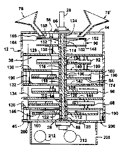
Referring now also to FIGS. 3 and 4, housing 12
has nine longitudinally extending side walls 40 forming a
regular polygon shape in latitudinal cross section. The
interior surface of housing 12 has an inscribed diameter
of approximately 23.5 inches. Sides 40 form 40° apices,
or interior corners 42, where they meet. Sides 40 and
interior corners 42 extend longitudinally between a top
plate 44 and a bottom plate 46. Top and bottom plates
44, 46 are approximately 30.5 inches apart.
Top plate 44 is rigidly tied to shield 14 with
three strap assemblies 48 (FIGS. 1 and 2). Strap
assemblies 48 each include a bracket 50 welded to the
outer surface of shield 14, a rigid strap 52, and bolts
54, 56 connecting strap 52 to bracket 50 and top plate
44, respectively.
In the described embodiment, sides 40 are formed
of three panels 60, 62, 64, each including two full sides
40 and two partial sides 40, and three interior corners
42. Referring now also to FIG. 4A, each pair of panels,
e.g., 60 and 62, can be joined with an overlapping seam
66 located about midway between corners 42. Brackets 68
are welded to panel 60, and brackets 70 are welded to
panel 62 adjacent to seam 66. Bracket pairs 68, 70 are
tied together by fasteners, for example, with bolts 72
and nuts 74. A sealing joint material, such as, for
example, a silicon based sealant, can be used at seam 66
and other joints between pieces of housing 12 to make
housing approximately air-tight.
CA 02296341 2000-O1-17
WO 99/03589 PCT/US98/14852
- 12 -
Referring again to FIGS. 2 and 3, bottom plate 46
is supported from a portion of annular plate 16 that
extends radially inward a short distance from shield 14.
A gasket (not shown) providing a liquid seal is placed
between annular plate 16 and bottom plate 46. A J-bolt
arrangement (not shown) can be employed for ensuring a
positive seal with the gasket. Bottom plate 46 is
secured to panels 60, 62, 64 with nine threaded fasteners
65 that extend through apertures formed in respective
fittings 67 attached to panels 60, 62, 64, and that screw
into threaded holes 58 arrayed around the periphery of
bottom plate 46. Top plate 44 is bolted to threaded
fittings 75 on panels 60, 62, 64 with threaded fasteners
76.
A feed chute 78 for introducing material to be
pulverized (or otherwise processed) into housing 12
extends through an aperture 80 in top plate 44. For
clarity of illustration, feed chute 78 is illustrated at
a position in FIG. 2 that is different from the position
depicted in FIG. 1. Feed chute 78 includes a rectangular
shaped tube 82 that is oriented relative to the plane of
top plate 44 at an angle of approximately 44 degrees.
Feed chute 78 also has a funnel 84 at its top end and a
bracket 86 for attachment to top plate 44. Tube 82 is
approximately 13.25 inches long, extends approximately
1.375 inches below the bottom side of top plate 44, and
has interior dimensions of 3 X 4 inches. Tube 82
includes a flange 85 for attaching feed chute 78 to top
plate 44, e.g., with threaded fasteners.
The rotor assembly 38 will now be described in
detail with reference to FIGS. 1 and 4-6. Rotor assembly
38 includes a rotatable shaft 28 that extends
longitudinally through housing 12. Shaft 28 extends
through a top bearing assembly 86 that is bolted to top
plate 44. Sprocket speed indicator assembly 36 and
CA 02296341 2000-O1-17
WO 99/03589 PCT/US98/14852
- 13 -
sheave 26 are positioned on shaft 28 above top bearing
assembly 86. A bottom bearing assembly 88 is bolted to
' the bottom side of bottom plate 46. Shaft does not
extend through bottom bearing assembly 88.
Within housing 12, there are six longitudinally
spaced rotors 90, 92, 94, 96, 98, 100, each being fixed
to a respective hub 102, 104, 106, 108, 110, 112 that is
coupled to shaft 28 by two keys (not shown). Spacers
114, 116, 118, 120, 122, which are also keyed onto shaft
28, are positioned between adjacent pairs of hubs 102,
104, 106, 108, 110, 112. Spacers 124 and 126 are
positioned adjacent top plate 44 and bottom plate 46,
respectively. Spacer 124 is also secured to shaft 28
with a set screw (not shown). Shaft 28 can be fabricated
is made of 2 inch diameter 4140 alloy steel. The
diameter of each spacer is approximately 3.5 inches. The
longitudinal position of one or more than one of rotors
90, 92, 94, 96, 98, 100 can be adjusted by changing the
length one or more of spacers 114, 116, 118, 120, 122,
126.
Orifice plates 128, 130, 132, 134 and 136 are
positioned between adjacent pairs of rotors 90, 92, 94,
96, 98 and 100. Orifice plates 128, 130, 132, 134, 136
each extend to sides 40 of housing 12. Each of orifice
plates 128, 130, 132, 134, 136 includes a central
aperture, which, with its respective spacer 114, 116,
118, 120, 122, provides an annular shaped orifice 138,
140, 142, 144, 146 therebetween.
In the described embodiment, each of shield 14,
annular plate 16, top plate 44, bottom plate 46, panels
60, 62, 64, rotors 90, 92, 94, 96, 98, 100, and orifice
plates 128, 130, 132, 134, 136 are fabricated of 0.5 inch
thick low-carbon steel, such as, for example, 1020 steel.
These components may be fabricated from different
materials, including harder materials and softer
CA 02296341 2000-O1-17
WO 99/03589 PCT/US98/14852
- 14 -
materials, depending upon the-intended application for
pulverizer 10.
Referring now also to FIG. 7, the topmost rotor
90, which will also be referred to as a distributor
rotor, is positioned closest to where material is fed
into housing 12 via feed chute 78. Distributor rotor 90
includes a distributor rotor plate 148 having a regular
pentagonal-shaped peripheral edge forming five apices, or
outside corners 150. Five distributor rotor vanes 152
extend upwards toward top plate 44 from the top side of
distributor rotor plate 148 (only three vanes are shown
in FIG. 7 for clarity). Each distributor rotor vane 152
also extends approximately radially inward from an
outside corner 150 to hub 102. Vanes 152 can be fixed to
distributor rotor plate 148 and hub 102 by welding.
Alternatively, each distributor rotor vane 152 can fit
into a corresponding slot 154 formed in distributor rotor
plate 90, and secured by threaded fasteners 156, e.g.,
bolts, that extend through apertures 158 in distributor
rotor plate 90 and screw into corresponding threaded
holes 160 in distributor rotor vane 152. An upper edge
162 of each distributor rotor vane 152 is sloped upwards
from an elevation of about 1 inch at 102 to an elevation
of about 1.5 inches near the periphery of plate 148. A
pentagon-shaped distributor ring 164, which is about 1.5
inches wide, is welded to the upper edges 162 of
distributor rotor vanes 152.
Each of distributor rotor plate 148, distributor
ring 164, and distributor rotor vanes 152 are fabricated
from 0.5 inch low-carbon steel plate. Distributor rotor
is circumscribed by a 17 inch diameter circle and is
approximately 2.7 inches high. Distributor ring 164 is
located approximately 1.625 inches below top plate 44 and
approximately 0.25 inches below a discharge opening 166
of feed chute 78. Discharge opening 166 of feed chute 78
CA 02296341 2000-O1-17
WO 99/03589 PCT/I3S98/14852
- 15 -
is positioned such that when a center of a chord of
distributor ring 164 is aligned with discharge opening
' 166, a radially innermost edge 168 of discharge opening
166 extends about 0.5 inches inwardly beyond an inner
edge 170 of distributor ring 164. When a corner 150 of
distributor rotor 90 is aligned with feed chute 78, the
outside of discharge opening 166 is completely inside
distributor ring 164. This provides a large area to feed
material into slots between distributor rotor vanes 152,
and discharges the material from feed chute 78 onto rotor
90 as radially distant from hub 102 as possible. For
reasons that will be discussed below, each vane 152 is
positioned such that when rotor assembly is spinning, a
trailing outer edge 172 of each distributor rotor vane
152 is shaped to be about aligned with the peripheral
edge of distributor rotor plate 148 at a trailing edge of
an apex 150, either without any overlap or with
distributor rotor vanes 152 extending slightly over the
edge of distributor rotor plate 148.
Other rotors 92, 94, 96, 98, 100 are designed
differently from distributor rotor 90, but similarly to
each other. Rotor 94 will be described as an example,
with reference to FIG. 8. Rotor 94 includes a rotor
plate 174 having a regular nine-sided polygonal
peripheral edge 176 forming nine apical corners 178.
Rotor plate 174 is welded or otherwise rigidly coupled to
hub 106. Rotor 94 also includes nine curved vanes 180,
each extending approximately radially inward toward hub
106 from a respective one of the apical corners 178.
Vanes 180 are approximately six inches long and extend
. approximately one inch above rotor plate 174, which is
about 0.5 inches thick. For most uses of pulverizer 10,
the interior curve of each of vanes 180 faces into the
direction in which rotor assembly turns. Rotor plate 174
is fabricated from 0.5 inch low-carbon steel plate, and
CA 02296341 2000-O1-17
WO 99/03589 PCT/US98/14852
- 16 -
vanes 180 are fabricated from 0.5 inch wall, 8 inch outer
diameter steel tubing. Vanes 180 are set in respective
0.125 inch deep grooves (not shown) formed on an upper
face of rotor plate 174, and secured in place with three
threaded fasteners (not shown) that extend through
apertures formed in rotor plate 174 (not shown), in a
manner similar to that described above with reference to
distributor rotor 90 illustrated in FIG. 7. This
arrangement permits simple removal and replacement of
vanes 180. Alternatively, rotors 180 may be welded to
rotor plates 174, or otherwise affixed to rotor plates
174. Outer trailing edges 182 of vanes 180 are beveled
at an angle to align with peripheral edge 176 of rotor
plate 174 such that there is no overlap between rotor
plate 174 and vane 180, or so that trailing edge 182
extends slightly over edge 176 of rotor plate 174 on the
trailing side of an apical corner 178.
The other rotors, rotors 92, 96, 98 and 100, are
configured similarly to rotor 94, each having a nine-
sided peripheral edge 176 and curved vanes 180 extend
radially inward from apical corners 178 toward respective
hubs 104, 108, 110 and 112. In the embodiment
illustrated in FIG. 5, rotors 92, 94, 96, 98 and 100 are
circumscribed by circles having diameters of 17, 19, 21,
21, and 21 inches, respectively. Each of vanes 180 is
approximately 6 inches long about its outer perimeter and
shaped at its apical corner 182 so that there is little
or no overlap between vane 180 and rotor plate 174 at its
trailing edge 182. Each of rotors has a height of
approximately 1.5 inches. Because rotor 92 is smaller
than the other rotors and vanes 180 are the same size on
all rotors 92, 94, 96, 96, 100, each of vanes 180 on
rotor 92 extend approximately to hub 104, whereas vanes
180 on rotors 94, 96, 98, 100 do not extend all the way
CA 02296341 2000-O1-17
WO 99!03589 PCT/US98/14852
- 17 -
to hubs 106, 108, 110, 112, respectively, a gap being
provided therebetween.
Referring now also to Fig. 9, orifice plate 128
can be fabricated from 0.5 inch low-carbon steel plate.
Its peripheral edge 184 forms a nine-sided polygon sized
to fit closely against sides 40 of housing 12. Orifice
plate 128 includes a central aperture 186 formed by inner
rim 188, which, with spacer 114, provides annular-shaped
orifice 138 therebetween. Orifice plates 130, 132, 134,
and 136 are similarly configured. Orifice plates 128,
130, 132, 134, and 136 have apertures 186 with diameters
of 7, 8, 9, 10 and 11 inches, respectively.
Referring back to FIGS. 4 and 5, and also to FIGS.
l0A and lOB, orifice plates 128, 130, 132, 134, 136 are
supported independently of panels 60, 62, 64 by support
pins 190. Support pins 190 can be fabricated from 2 inch
diameter steel rod. Three equally spaced apart pins 190
are positioned between each neighboring pair of the
orifice plates. Each support pin 190 is located at an
apical corner 192 of an orifice plate so that it is
adjacent an interior corner 42 of housing. As shown in
FIGS. 5 and 9, support pins 190 on one side of an orifice
plate, e.g. orifice plate 128, are offset by one apex
(40°) from support pins 190A on the other side of that
orifice plate.
Support pins 190 are attached to the orifice
plates by threaded fasteners 194, e.g., bolts, that
extend into counter-sunk through holes {not shown) formed
in the orifice plates and into threaded holes 196 formed
in pins 190. Three support pins 190 that are attached to
an upper side of orifice plate 128 can also be attached
to top plate 44 with threaded fasteners. For example,
bolts 56, which are also employed to hold straps 52 as
described above with reference to FIG. 2, can be employed
to fasten to these three pins 190. Three support pins
CA 02296341 2000-O1-17
WO 99/03589 PCT/US98/14852
- 18 -
190 that are attached to a bottom side of orifice plate
136 can also be attached to bottom plate 46. Bottom
plate 46 includes three apertures 198 through which
threaded fasteners 200 (shown in FIG. 5) can be inserted
for fastening to these three pins 190.
Referring again to FIG. 6, bottom plate 46
includes a web 202 forming four apertures 204 through
which pulverized material is discharged from housing 12.
A 23 inch diameter skirt 206 depends from bottom plate 46
just outside of apertures 204. Web 202 supports rotor
assembly 38 from bottom bearing assembly 88, which is
bolted to web 202. The size of web 202 is made as small
as possible to maximize the size of apertures 204 within
skirt 206.
The diameter of skirt 206 is sized to fit into a
55 gallon open barrel 208, which rests on rollers 209. A
fabric belt 210 is employed between skirt 206 and barrel
208 to inhibit fine pulverized particles from escaping.
Skirt 206 includes four apertures 212 (only two shown in
FIG. 3). Each aperture 212 includes a bolt circle
employed for attaching a respective 6 inch diameter tube
214 (only two shown in FIGS. 1 and 2). Tubes 214 extend
approximately radially outward from skirt 206, and each
tube 214 has a fabric filter bag 216 removably attached
to it. Air is exhausted from pulverizer 10 through tubes
214. Filter bags 215 and catch fine particles and allow
air to pass through.
In the described embodiment, rotors 90, 92, 94,
96, 98, 100 and orifice plates 128, I30, 132, 134, 136
are positioned as follows: The top surfaces of orifice
plates 128, 130, 132, 134, and 136 are respectively
located approximately 2.875, 2.125, 1.875, 1.625, and
1.375 below the bottom surfaces of respective rotors 90,
92, 94, 96, and 98. Orifice plates 128 and 130 are
approximately 5 inches apart; orifice plate 130 and 132
CA 02296341 2000-O1-17
WO 99/03589 PCT/US98114852
- 19 -
are approximately 4.5 inches apart; orifice plates 132
and 134 are approximately 4 inches apart; and orifice
plates 134 and 136 are approximately 3.5 inches apart.
The tops of vanes 180 on rotors 92,_94, 96, 98 and 100
are about 1.375, 1.187, 0.875, 0.625, and 0.5 inches
below respective orifice plates 128, 130, 132, 134, and
136. Rotor 100 is positioned approximately 1.75 inches
above bottom plate 46. Rotors 92, 94, 96, 98 and 100 are
rotated relative to their next nearest rotor by about
13.3 degrees.
It can be seen that rotors 90, 92, 94, 96, 98, 100
of rotor assembly 38 have sizes that generally increase
with increasing distance from a top end of housing 12
through which material to be pulverized or otherwise
processed is introduced into housing. The smallest
rotors 90, 92 are located closest to top plate 44, the
largest rotors 96, 98, 100 are positioned closest to
bottom plate 46, and an intermediate sized rotor 94 is
positioned about midway between top plate 44 and bottom
plate 46. This arrangement is particularly adapted for
pulverizing large size objects. If the feed material
comprises smaller sized particles, on average, the rotors
could be of a more uniform, larger size. In some
applications, it may be advantageous to have rotors that
are all the same size, or to alternate between larger and
smaller rotors in some fashion.
In addition, orifices 138, 140, 142, 144, 146 are
of generally increasing size with increasing distance
from the top end. This arrangement is used to maintain a
negative back pressure at each stage. For other
applications, this arrangement could be reversed, the
orifices could be a more uniform size, or the orifice
sizes could be varied in a different manner from one end
of housing 12 to the other.
CA 02296341 2000-O1-17
WO 99/03589 PCTNS98/14852
- 20 -
The spacing between each orifice plate and the
rotor next below it generally decreases with increasing
distance from top to bottom. Moreover, the rotors and
orifice plates are positioned such that the spacing
between adjacent orifice plates generally decreases from
top to bottom. This decreases the volume in stages
between the top and bottom of rotor assembly 38.
Material flowing through an orifice in pulverizer
first undergoes a velocity increase and an
10 accompanying decrease in pressure. Then, because the
available volume decreases at each succeeding stage, the
material flowing through pulverizer 10 experiences a
rapid compression, which in turn can cause a rapid
increase in pressure and/or temperature. The size of the
orifice is increased with each succeeding stage to
provide a pressure immediately downstream of an orifice
that is lower than the pressure immediately upstream the
orifice. This negative back pressure that is maintained
across each orifice helps to maintain the flow.
I tested the above-described pulverizing system
with several different feed-stock materials of widely
varying composition, hardness, ductility, and moisture
content. My tests lead me to believe that material
introduced into pulverizer with rotor assembly spinning
at speeds of approximately 1000 revolutions per minute
(rpm) or greater are pulverized primarily by shock waves
generated within housing 12. My observations indicate
that material fed into feed chute 78, as well as air
entering through feed chute 78, is accelerated rapidly
and is then entrained into a fluid-like flow through the
spinning rotor assembly 38. It appears that the material
in the flow is almost immediately subjected to a rapid-
fire succession of shock waves, which may begin to break
up the feed-stock material even before it reaches the
distributor rotor.
CA 02296341 2000-O1-17
WO 99/03589 PCT/US98/14852
- 21 -
The spinning rotors 90, 92, 94, 96, 98, 100 create
a very strong air flow through housing 12. It appears
that material fed into pulverizer 10 through feed chute
78 is entrained in this flow. The material apparently
flows, with the air flow, through pulverizer 10 making
minimal contact with sides 40 of housing 12 or with
orifice plates 128, 130, 132, 134, 136. This, I believe,
is due to the flow being influenced by the Coanda effect
to closely follow the contours of the rotor peripheries
174 and orifice rims 188. For this reason, I call the
flow through pulverizer of material and air a "Coanda
flow." The Coanda effect helps to reduce high-angle
contacts between the flowing material and the component
parts of pulverizer 10, and thereby reduce wear on these
parts. Distributor ring 164 acts as a shroud to enhance
the Coanda effect.
The Coanda flow rapidly changes direction as it
rounds the peripheral edge of each rotor and the rim of
each orifice, alternating between a flow that is directed
radially outward and a flow that is directed radially
inward. The sizes of the orifices increase with each
succeeding stage to maintain a negative back pressure
throughout rotor assembly 38, which helps to keep the
velocity of air and particles sufficiently high to
maintain the Coanda flow.
I have observed that when vanes 152, 180 are not
positioned on the trailing side of apical corners 150,
178, respectively, rotor plates 148, 174 experience wear,
becoming slightly rounded on the underside adjacent and
downstream from where vanes 152, 180 attach. This is
_ evidence that the material is entrained in a Coanda flow
that closely follows the contour of the periphery of each
. rotor. The leading side of each rotor vane 152, 180,
particularly in the region close to its respective rotor
plate 148, 174, also shows increasing wear with proximity
CA 02296341 2000-O1-17
WO 99/03589 PCT/US98/14852
- 22 -
to its outer edge. There is -also a tendency for material
to ride up the side of the vane as the material is moved
radially outward by the vane. However, the wear pattern
shows little scoring or pitting, which would be expected
if the material was not entrained in a Coanda flow.
These are the only areas of rotors at which I have
noticed wear. Sides 40 and orifice plates 128, 130, 132,
134, 136 show some evidence of some large particle
impacts, but no wearing pattern as observed on the
rotors.
To enhance the Coanda effect on the material
flowing past vanes 152 and 180 and around rotor plates
148, 174, outer edges of the vanes can be beveled and
aligned with the peripheral edge of the respective rotor
plate 150 and 174. The leading edge of each vane 152,
180 should go at least to the respective apex 150, 178 of
the respective rotor plate 148, 174. Positioning vanes
152, 180 such that their outer edges are on the trailing
side of apical corners 150, 178 should reduce the amount
of wear.
Shock waves may be generated each time the flowing
material experiences a rapid acceleration, such as when
the direction of flow rapidly changes, or experiences a
pressure change. Such shock waves may generate large
voltages due to the piezoelectric properties of the
materials, as they experience rapid compression or
decompression. Some places where large accelerations may
take place include at discharge opening 166 of feed chute
78, going around vanes 152, 180, going around distributor
rotor plate 148 and around rotor plate peripheral edges
176, and going around rims 188 of orifices 138, 140, 142,
144, 146. Large pressure changes may take place when the
flow passes through an orifice or when the flow is pumped
by a rotor.
CA 02296341 2000-O1-17
WO 99/03589 PCT/US98/14852
- 23 -
A non-uniform electromagnetic field may also be
generated within housing 12 as rotor assembly 38 rotates.
Rotors 90, 92, 94, 96, 98, 100, as well as housing 12 and
orif ice plates 128, 130, 132, 134, 136, are all made of
low-carbon steel, which is ferromagnetic. The spinning
rotors would create a rapidly changing, non-uniform
electromagnetic field. These electromagnetic fields
could enhance piezoelectric effects in the material in
the Coanda flow.
Primary pulsed standing shock waves may also be
produced as vanes 152, 180 on rotors 90, 92, 94, 96, 98,
100 alternately pass sides 40 and corners 42 of housing.
Decompression would occur as the rotors pass each empty
interior corner 42 of housing 12, and compression would
occur as the vanes pass the center of each side 40. A
shock wave of this type would be created every 40 degrees
of rotation of a vane.
Moreover, secondary pulsed standing shock waves
may be produced as vanes 152, 180 pass by support pins
190, three of which are located proximate each rotor.
Vanes 180 of the largest rotors, rotors 96, 98, 100, pass
within about 0.1 inches of support pins 190. These shock
waves would be produced every 120 degrees of rotation of
a vane on a rotor due to compression of the flow as the
vane passes each of the three support pins located near
the rotor. Twenty-seven shock waves are generated for
each rotation of a nonagon-shaped rotor. Thus, support
pins 190 are employed to support the orifice plates and
also to help generate shock waves. While in the
described embodiment cylindrical support pins are
employed for these purposes, a different arrangement can
be used to support the orifice plates, and differently
shaped members can be positioned in corners 42 opposite
respective rotor vanes 150, 180 for generating the
secondary shock waves.
CA 02296341 2000-O1-17
WO 99/03589 PCT/US98/14852
- 24 -
Before material is fed into pulverizer, rotor
assembly 38 is brought up to an operating speed of
rotation. The spinning rotors generate a large air flow
with negative back pressure through feed tube 78 and down
through pulverizer 10. Thus, any material fed into feed
tube 78 will be immediately drawn in and accelerated
rapidly towards distributor rotor 90.
As noted above, material may be broken apart while
accelerating down feed chute 78 and turning direction
exiting discharge opening 166. It is believed that
discharge opening 166 acts as an orifice through which
air and the feed-stock material flows into the larger-
volume region between top plate 44 and distributor rotor
90. The flow through this first orifice provided by
discharge opening 166 can cause a pressure change, which
may be accompanied by a temperature change. The pressure
change, along with the rapid acceleration of the
particles exiting feed tube 78, can cause a first shock
compression and/or expansion and an initial breaking
apart of some particles.
Smaller particles, less than about 1-1.5 inches in
size, are quickly entrained in the Coanda flow and would
flow through distributor rotor 90 between distributor
rotor plate 148 and distributor ring 164. Larger size
particles may be accelerated against sides 40 of housing,
which may break the particles apart further, such that
they bounce back inwardly and are entrained in the high
velocity Coanda flow.
Distributor rotor 90 has five apical corners,
rather than nine, to create longer wavelength shock
waves, which I have found to be effective for breaking up
larger particles. For this reason, in other embodiments
that may be used for breaking up very hard materials,
rotors 92, 94, 96, 98 and 100 may be configured with a
generally increasing number of sides with increasing
CA 02296341 2000-O1-17
WO 99/03589 PCT/US98/14852
- 25 -
distance from a top end of housing 12 through which
material is introduced. For example, distributor rotor
90 and rotor 92 could be configured as pentagons, rotors
94 and 96 as heptagons, and rotors 98 and 100 as
nonagons.
When the Coanda flow passes through orifice 138,
the particles experience a rapid directional change and
an increase in velocity with a corresponding pressure
rise. The flow is immediately compressed because the
volume between orifice plate 128 and rotor 92 is smaller
than the volume between rotor 90 and orifice plate 128.
This can also cause a rapid increase in pressure and an
accompanying temperature increase. At this stage, there
would still be some high-velocity impacts of larger
particles against sides 40 and against pins 190, the
larger particles bouncing off these structures or
breaking up and then colliding with particles in the
Coanda flow.
This process of rapid acceleration, expansion, and
compression is repeated as the flow passes through each
succeeding stage and rounds the rotors and orifices.
These rapid variations in pressure and acceleration of
the flowing material may contribute to creating shock
waves which pulverize material flowing through pulverizer
10. In addition, the rapid compressing and decompressing
of material in the flow can cause a build-up of
piezoelectric energy and subsequent releases in the
material, which may cause the break-up of some material
into smaller sized particles. It is believed that the
primary and secondary pulsed shock wave fronts are
reinforced by shock waves created by piezoelectric energy
releases in the flow. The rapid flow of material through
the non-uniform electric and magnetic fields within
pulverizer 10, which are generated by the spinning
rotors, may also contribute to piezoelectric compression
CA 02296341 2000-O1-17
WO 99/03589 PCT/US98/14852
- 26 -
and decompression of material in the flow, thus also
contributing to generating shock waves in the flowing
material.
in some tests, I measured voltages within housing --
12 at a location about midway between two corners 42 of
sides 40, opposite rotor 96. I observed voltage spikes
in the range of 100-200 kV, which I interpret to be
piezoelectric energy releases. To measure the voltage, I
used an oscilloscope to measure the voltage across a
spark plug having a gap of about 0.050 inches. The spark
plug was inserted through a hole in housing such that
only the terminals of the spark plug protruded into
housing. The spark plug would typically be destroyed
within about 30 seconds of introducing the feed-stock
material into pulverizer 10.
I have observed that pulverizer 10 heats a
material being pulverized such that virtually all free
moisture is driven off. All product comes out of
pulverizer 10 warmed to approximately 50-100 degrees
Celsius or higher. Electric discharges from the material
and the rapid expansion then compression after the flow
passes through each orifice may increase the temperature
of the flowing material and drive moisture out. It
appears that volatile organic materials are also
vaporized out of the flowing material or otherwise
transformed.
The piezoelectric energy releases and frictional
heating of particles in the flow likely contribute to the
observed general increase in temperature of the
pulverized material. However, I also observed that
flowing only air through pulverizer 10 caused housing 12
to warm substantially. Therefore, some of the heating
effect is also probably due to pressure changes in the
flowing material and energy dissipated from shock waves.
CA 02296341 2000-O1-17
WO 99/03589 PCT/US98/14852
- 27 -
The spacings between orifice plates, between
rotors and between adjacently located rotor and orifice
plates may be varied for a particular purpose. Changing
one or more of these spacings will affect the amount of
compression and decompression the flowing material
experiences, particularly as it flows through an orifice.
As the distance from the top plate increases in the
arrangement illustrated in FIG. 5, the spacings between
orifice plates, between rotors, and between orifice
plates and adjacently located rotors decreases, while the
sizes of the orifices and of the rotors increase. This
arrangement creates a pressure drop as the flow crosses
each orifice, while increasing the bulk material density
in the flow as the flow moves through succeeding stages
in the housing. The number of particles and the particle
density increases with each succeeding stage as more
material is pulverized. The increasing particle density
can cause the particles in the flow to grind against each
other, further pulverizing material into smaller
particles and heating the product.
Although the relative importance of each mechanism
is not yet fully understood, it is certain that large
particles are pulverized into smaller particles, and the
particles are heated and dried out by the process.
Specific tests will now be described.
Example 1: Aluminum Cans
I introduced whole, unwashed, aluminum beverage
cans into feed chute 78 with rotor assembly 38 spinning
at 3200 rpm. The beverage cans each included a plastic
liner and some included a beverage and/or other residue
of unknown origin. All the cans included painted
indicia. Pulverizer 10 produced rough-shaped aluminum
particles being 100% -10 mesh, and approximately 90-95%
+80 mesh. The pellets did not show any noticeable
CA 02296341 2000-O1-17
WO 99/03589 PCT/US98/14852
- 28 -
remnants of the plastic linings or leftover beverages,
and much of the paint was removed.
When housing 12 was opened after testing with
aluminum cans, there were a few pieces of aluminum
wrapped on the inside edge of distributor ring 164. This
problem may be eliminated by removing distributor ring
164 from distributor rotor 90.
Example 2: Clay
I fed a combination of clay chunks, which has an
origin in the vicinity of Golden, Colorado, having 35%
water content into pulverizer 10 with rotor assembly 38
spinning at speeds of 2000, 2500, 3000, and 3200 rpm.
The clay chunks were approximately 1-4 inches in size.
For each rotation speed, pulverizer 10 reduced the clay
chunks to a dry clay powder having a size distribution
range of 50~ 6 ~.m; gangue materials, including quartz,
that were in the clay deposit, were reduced to somewhat
larger sizes which could be easily separated by screening
or cyclonic separation. The water content was reduced to
a level where the clay powder product was noticeably
hydrophilic. After being left out overnight, the clay
powder product visibly reddened. This is evidence that
the particle sizes were small enough for the clay powder
product to auto-oxidize.
I repeated the test with dry clay ore and achieved
the same result. This provides evidence that pulverizer
10 can be effective in removing moisture from a feed
stock material.
Example 3: Gold Ores
(A) I fed chunks of quartz/serpentine gold ore,
which originated from the vicinity of Oatman, Arizona,
having a nominal size of approximately 1.5 inches into
pulverizer 10 with rotor assembly spinning at 3200 rpm.
Pulverizer 10 reduced the ore to a powder having a
particle size of approximately 5Oo -325 mesh. Many
CA 02296341 2000-O1-17
WO 99/03589 PCT/US98/14852
- 29 -
rough-shaped particles of gold were liberated from the
ore.
(B) I also tested a quartz/pyrite gold ore from
Costa Rica. 1.5 inch chunks of this ore were fed into
pulverizer 10 spinning at 3200 rpm. Pulverizer 10
reduced the chunks to particles of 100% -225 mesh size.
Gold and silver particles were both liberated from the
ore.
(C) I tested an Alaskan gold/copper sulfide ore
having 15% free carbon. I fed wet 3 inch chunks of this
ore into pulverizer 10 with rotor assembly 38 spinning at
about 3000 rpm. Pulverizer 10 produced particles sized
100% -325 mesh. The gold, along with all the free
carbon, appeared completely liberated. Copper sulfide
was also broken away from gangue material.
Example 4: Tires
I fed cut up pieces of steel-belted and fiber-
belted tires that were about 0.5 - 1 inch in size into
feed chute 78, with rotor assembly 38 spinning at about
3200 rpm. Pulverizer 10 produced a product in which the
fabric and steel components were substantially separated
from the rubber component. The fabric component, which
originally consisted of corded fibers, was reduced to
individual fiber strands that were, for the most part,
swept into filter bags 216 with exhaust air. The steel
and rubber dropped into barrel 208. Pulverizer 10
separated the steel into individual wire pieces up to
approximately 1 inch in length. some of the steel wires
were folded over. Rubber particles produced by
pulverizer were about an eighth of an inch in size. A
few fabric fiber strands tangled around particles of
rubber. The steel can be separated from the rubber by
conventional means, e.g. with a magnet.
CA 02296341 2000-O1-17
WO 99/03589 PCT/US98/14852
- 30 -
Example 5: Ceramic Balls
I fed a few hundred one inch ceramic balls,
obtained from Coors Ceramic Company, of Golden, Colorado,
into pulverizes 10 with rotor assembly 38 spinning at
about 3200 rpm. The ceramic has a hardness of at least 9
Moh. Pulverizes produced particles grains of about 950 -
100 mesh size. There was evidence that some of the balls
impacted components of rotor assembly 38 and side walls
40 at high velocity. The impacts left rounded dimples on
surfaces of the soft steel components of rotor assembly
38 and housing 12, principally in the region of
distributor rotor 90. Most surfaces showed little or no
dimpling. The dimples were almost all approximately
spherical-shaped, the largest dimple diameters being
about 0.28 inch diameter and about 0.03 inch deep. There
was very little damage to rotors 90, 92, 94, 96, 98, 100
or to orifice plates 128, 130, 132, 134, 136. The lack
of more extensive damage to rotor assembly 38 is evidence
that the pulverizes does not operate by smashing the
feed-stock against surfaces of sides 40 of housing 12.
Example 6: Perlite
I fed a Nevada perlite with corundum component,
sized up to 4 inches, into pulverizes with rotor assembly
spinning at 3200 rpm. The ore was reduced to a 50% 6 ~.m
powder. Corundum as well as other metallic particles
were completely liberated. In this test, I measured
voltages as high as about 170 kV with a spark plug, as
described above.
Example 7: Glass Bottles
I fed a mix of different colored glass bottles,
some being whole, some being broken, some having
metal/plastic caps attached and contents sealed within
the bottle, and some having some unknown food/dirt
content, into pulverizes 10 with rotor assembly 38
spinning at about 3200 rpm. Pulverizes separated the
CA 02296341 2000-O1-17
WO 99/03589 PCT/US98/14852
- 31 -
material into component parts: a dry, fine glass powder
about 10 um; cap chunks; shreds of paper labels up to 1/8
inch size; small bits of aluminum foil folded but not
balled; and a few pieces of rubber chunks from bottle cap
seals. There was no evidence of organic residues other
than a grey, clay-like, floatable dust.
I did a second test of bottles of mixed colors,
with rotor assembly 38 spinning at about 2500 rpm. For
reasons that are not fully understood, different color
glass components were pulverized to different coarseness.
Clear glass was ground the finest, green glass was ground
somewhat coarser, brown coarser yet, and yellow the
coarsest. This could have applications in the recycling
industry or other applications where it is undesirable to
mix different colors of glass. It is possible that the
separation process could be improved at slower rotational
speeds.
Example 8: Wollastonite
New York wollastonite (CaSi03) particles, being -
.5 inch mesh size, were fed into pulverizer 10 with rotor
assembly spinning at about 2000 rpm. Pulverizer 10
appeared to completely liberate the wollastonite fibers
and gangue material. The product fibers had a length to
diameter ratio of greater than about 20.
Example 9: Catalytic Converters
I introduced ceramic pieces from automobile
catalytic converters into pulverizer 10. After passing
the material through pulverizer six times with rotor
assembly 38 spinning at about 2500 rpm, pulverizer 10
produced visible, panable pieces of Pt group metals (Pt,
Pd, Rh). I measured sparks with a voltage of
approximately 100kV with a spark plug and oscilloscope.
Example 10: Calcined Alumina
Calcined alumina particles having a nominal size
of approximately 50 hem were fed into pulverizer 10 with
CA 02296341 2000-O1-17
WO 99/03589 PCT/US98I14852
- 32 -
rotor assembly 38 spinning at 3200 rpm. Pulverizer
reduced the nominal particle size to 50% 6 Vim.
Example 11: Calcium Carbonate
I fed calcium carbonate of sizes ranging from 6 um
- 1 inch into pulverizer 10 spinning at 3200 rpm.
Pulverizer reduced the particle size distribution to 50%
6 ~,m .
The basic design of a pulverizer can be modified
to suit a particular purpose. For example, a second feed
chute 78A can be employed at a position diametrically
opposed to feed chute 78, as illustrated in FIG. 5, to
introduce a process material to pulverizer 10
simultaneously with introducing a feed-stock material to
be pulverized and processed through feed chute 78. The
process material may be in liquid or dry form, or can
even be a gaseous material. The feed-stock material can
be dry discrete objects or a wet material, and can be of
uniform composition or a composite. In this way, the
feed-stock material can be chemically processed,
sterilized or otherwise altered by interacting with the
process material as the starter material is pulverized
into smaller particles and/or dried.
Alternatively, second feed chute 78A can be
employed to introduce a reaction-inhibiting material,
such as, for example, an inert or non-reactive gas or
liquid, into housing 12 to inhibit a chemical alteration,
such as oxidation, of the starter material. Second feed
chute 78A can also be employed to feed additional
quantities of the same material as is introduced into
housing 12 through feed chute 78.
Second feed chute 78A may be configured
differently from feed chute 78. For example, feed chute
78A can be adapted particularly for introducing a liquid
or gaseous process material into pulverizer. In one
example, chlorine can be introduced into feed chute 78A
CA 02296341 2000-O1-17
WO 99/03589 PCT/US98/14852
- 33 -
for disinfecting organic wastes. A regulator valve 79
can be employed with feed chute 78A to regulate the flow
of the liquid or gaseous material into housing for
optimizing the process. Finally, feed chute 78A can also
be employed for permitting additional air to be
introduced into housing, the air flow being regulated by
regulator valve 79.
While in the described embodiment, housing 12 has
nine sides 40, a housing with as few as five and as many
as eleven sides may be employed. An odd number of sides
40 is preferred because it reduces the likelihood of
resonances being developed. For the same reason, I have
employed an odd number of pins 190 and have employed
rotors 90, 91, 94, 96, 98, 100 that have an odd number of
corners and vanes, although an even number of pins and
rotors that have an even number of corners and vanes may
be employed as well. Rotors with as few as five and as
many as thirteen sides can be used. More or fewer than
three support pins may be used opposite each rotor.
The shapes of rotor plates 148, 174 can be varied
from a strictly polygonal shape. For example, a small
amount of rotor plate 148, 174 may be scalloped out
immediately behind the trailing edge of each of vanes
152, 180, respectively. This may enhance the Coanda flow
and reduce wear on rotor plates 148, 174 in this region.
It may be advantageous to run rotor assembly 38 in
reverse. Rotor vanes 180, being curved in the direction
of rotation, would not scoop flowing material as they do
when rotating in the forward direction. Instead, the
flowing material would slip more easily off the outer
tips of vanes 180. This may be desirable where it is
necessary to run at a high rotational speed but a very
fine particle size is not wanted. This method may be
employed for producing cracked wheat or for cracking
other grains.
CA 02296341 2000-O1-17
WO 99/03589 PCT/US98/14852
- 34 -
Shield 16 can be configured for flowing water,
another liquid or a gas therethrough to act as a heat
sink or source for pulverizer 10 in a heat exchanger.
This could be important in some applications, for
example, where a temperature-sensitive chemical process
is being undertaken as a material is being pulverized.
Referring now to FIG. 11, each of vanes 180 may be
positioned to provide a small overhang 220 over the edge
176 of the rotor plate to which it is attached. Overhang
220 would be no more than about a thirty-second of an
inch, and
would enhance the Coanda flow. Note that vane 180
illustrated in FIG. 11 is also positioned such that
overhang 220 is shaped similar to edge 176 of rotor plate
174, and an outer tip 222 of its leading surface 224 is
positioned about over apical corner 178. The arrow in
the figure indicates a direction of rotation.
Referring now to FIG. 12, vanes 180 may also be
modified to have a curved profile, like a turbine blade,
on its leading surface 224 with respect to a direction of
rotation (arrow) to provide a more efficient pumping
action.
The materials employed for making components of
pulverizer can be modified from those described above to
suit a particular application. For example, for
pulverizing very hard materials, rotors can be
manufactured from a more durable alloy, or have a coating
that is resistant to wear or to damage from impacts.
Pulverizer 10 does not need to be arranged
vertically, with feed chute 78 located at the top. In
some applications, such as, for example, when employed as
an air scrubber, material may flow in from a bottom end
or pulverizer may be arranged at an angle to vertical.
A pulverizer may be configured for a particular
application with more than six or less than six rotors,
CA 02296341 2000-O1-17
WO 99/03589 PCT/US98/14852
- 35 -
and with a commensurately increased or decreased number
of orifice plates.
Other variations and modifications can be made to
the described embodiments without departing from the
spirit of the invention, the scope of which is defined in
the following claims.