Note : Les descriptions sont présentées dans la langue officielle dans laquelle elles ont été soumises.
CA 02297217 2000-O1-26
DEVICE FOR COMBINED URINARY DRAINAGE AND
CATHETERIZATION OF INCONTINENT MALE HUMAN BEINGS
The invention relates to a device for a
combined drainage of urine and catheterization of
incontinent male persons, in particular in the case of
paraplegia, with a condom having in its front region an
orifice adapted for adhering to the body of the penis,
a connector adapted for connecting in leakproof manner
to the orifice of the condom and for detachably
connecting to a urine collector, and a catheter,
wherein the connector must be removed for enabling
catheterization.
For managing incontinence of male persons, in
particular in the case of paraplegia, essentially two
different methods are known from practice. Thus, there
exists already a urine drainage system, wherein a dip
or injection molded part similar to a condom and made
of an elastic material, for example, silicon or the
like, is secured with an adhesive to the penis body to
prevent a reflux. Through an orifice in the front
region of the condom and through a connector provided
in this region, the urine is drained via a hose into a
bed or leg pouch.
An alternative to the foregoing, briefly
discussed urine drainage system is the so-called
intermittent self-catheterization (ISK), by which an
incontinent male person catheterizes himself four to
six times a day. To remain continent between the
catheterizatic~n phases, the treating physician normally
prescribes a medication that reactivates or deactivates
the bladder. However, all suitable medications have
' CA 02297217 2000-O1-26
2
the very great disadvantage that they dry up the mucous
membranes of the human body, which is felt by the
patient as discomfort or even as causing pain.
Within the scope of the intermittent self-
catheterization, one could do entirely without
corresponding medications to the exclusion of the side
effects caused by the medications. However, one would
have to connect a urine drainage system at least
between the catheterization phases. This means that
one would have to secure a condom to the body of the
penis with an adhesive or adhesive tape that is
tolerant to the skin as in the case of the conventional
urine drainage system. Depending on the frequency of
the catheterization -- four to six times a day -- the
urine drainage system would have to be attached by an
adhesive and be likewise again removed. Even with the
use of skin-tolerant adhesives, this will lead to an
enormous stress of the skin and lastly to quite
considerable additional costs by the increased use of
material.
It is therefore the object of the present
invention to describe a device for a combined drainage
of urine and catheterization of incontinent male
persons, which requires that the condom be attached by
means of an adhesive only once a day, preferably early
in the morning after a hygienic treatment, and which
yet ensures a simple and hygienic handling of the
catheterization.
The foregoing object is accomplished by a
device with the characteristic features of claim 1.
Accordingly, a device for the combined drainage of
urine and catheterization of incontinent male persons
of the above-described kind is characterized by an
expanding attachment, which assists in stretching the
CA 02297217 2000-O1-26
3
orifice so far that the condom can be slipped, together
with the expanding attachment, from the orifice over
the glans and over at least a portion of the penis body
toward the body.
It has been recognized by the present
invention that even in the case of multiple daily
catheterization, it is basically possible to apply a
urine drainage system with a condom for deactivating
the bladder, while doing without the usual medications.
This application occurs once a day, for example, in the
morning after a hygienic treatment. For the
catheterization, the orifice of the condom at the front
end that is freed from connecting means, is widened by
means of a special expanding attachment and slipped
back over of the penis body, so that the glans is fully
exposed and can be cleaned before the catheterization.
Subsequently --- after the catheterization -- the condom
is again pulled forward over the glans by means of the
expanding attachment. The expanding attachment
retracts again, so that the orifice is allowed to
contract. Thereafter, it is possible to reattach the
connector, thereby facilitating connection to the urine
drainage system.
A further advantage of the device according
to the invention is to be seen in that the expanding
attachment is used on the one hand for handling the
condom and on the other hand for supporting the penis
body during the catheterization. In any event, it is
possible to do without the medications that are to be
normally taken in the case of intermittent self-
catheterization, thereby precluding the side effects
occurring in that process. A catheterization at the
desired intervals is possible without taking
medications, which is in this instance a combination of
°
CA 02297217 2000-O1-26
4
intermittent self-catheterization and drainage of
urine.
At this point, it should be remarked one more
time, that beyond its actual task, the expanding
attachment is also used for positioning the body of the
penis during the insertion of the catheter.
Accordingly, it would be possible to design and
construct the expanding attachment in the way of a
supporting part. In this instance, it will be
necessary to ensure workability both for persons with
intact function of their fingers and for persons with
limited function of their fingers.
As regards a concrete realization of the
expanding attachment, it will be of advantage, when
same is constructed as an expanding ring. As
previously described, for purposes of catheterizing,
the small orifice of the condom is freed from the
connector. Thereafter -- with the use of the expanding
attachment -- the expanding attachment engages and
opens the orifice so far that it is possible to slide
the condom back, together with the expanding ring, over
the glans and beyond the penis body toward the body,
for purposes of exposing the glans, on the one hand for
cleaning or disinfecting, and on the other hand for
subsequently inserting the catheter. During
catheterization, the expanding attachment constructed
as an expanding ring provides the penis body with an
adequate support, so that the thus-realized support
facilitates catheterization even with a limited
mobility of the fingers.
Furthermore, it is essential for the
expanding attachment or for the expanding ring that it
be an aid for multiple or permanent use. The same
" CA 02297217 2000-O1-26
applies to the connector yet to be described in greater
detail.
As regards a concrete embodiment of the
expanding attachment -- constructed in the way of an
5 expanding ring -- it will be quite especially
advantageous, when the expanding attachment comprises
expanding fingers that are arranged approximately
coaxially in annular shape for insertion into the
unstretched orifice of the condom. For expanding the
orifice to a larger radius, the expanding fingers are
adapted for moving apart. Naturally, before using the
expanding attachment, it is necessary to release the
connector and remove it from the condom.
More specifically, it would be possible to
arrange the expanding fingers such that they can move
apart from and toward one another in the fashion of a
diaphragm. Insofar, it would be possible to expand the
opening of the condom quasi in an infinitely variable
manner and to make it also again smaller by a
contraction in the fashion of a diaphragm, so that it
is subsequently possible to reattach the connector to
the orifice.
The expanding fingers serving to engage the
orifice of the condom project from the expanding
attachment approximately orthogonally and are jointed
to the expanding attachment by means of a lever
arrangement. In this arrangement, each expanding
finger could connect to a pivoting lever arm, the
expanding finger and lever arm extending approximately
in L-shape.
In a further advantageous manner, the
expanding attachment or expanding ring could comprise
two oppositely rotatable annular disks, the annular
disks oppositely engaging guide elements and being
°
CA 02297217 2000-O1-26
6
interconnected for rotation. The rotational engagement
could be realized by means of conventional engaging
elements, detents, snap rings, or the like. With that,
the lever arrangement and likewise the lever arms are
positively guided in their pivotal movement between the
annular disks.
Concretely, the lever arms could be jointed
for pivotal movement to one of the annular disks and be
guided by guide elements along the respectively other
annular disk such that an opposite rotation of the
annular disks causes the lever arms to pivot by a
predetermined range. In this instance, the expanding
fingers of an annular arrangement with a small diameter
are displaceable to an annular arrangement with a
larger diameter, and vice versa, thereby resulting in
the movement of the expanding fingers necessary for
expanding and likewise for contracting again in the way
of the movement of a diaphragm.
The guidance of the lever arms between the
two annular disks can be realized in different ways.
Thus, the guide elements could be designed and
constructed as cover plates that guide the lever arms.
These cover plates would have to be constructed and
arranged such that they allow a pivotal and a tilting
movement of the guide elements. Accordingly, a
corresponding play is to be provided.
Likewise, it would be possible to design and
construct the guide elements -- in a quite advantageous
manner -- as pins engaging guide slots of the lever
arms, thereby defining -- per se -- a pivotal movement
of the lever arms. Since the guide elements engage
guide slots formed lengthwise in the lever arms, it is
possible to move the pivoting axis -- as defined by the
guide elements.
" CA 02297217 2000-O1-26
7
As regards a simple actuation of the
expanding attachment, it will be of advantage, when the
annular disks comprise gripping regions on their outer
edge for a better handling. These gripping regions
could be profilings in the outside wall of the annular
disks. In particular when the expanding attachment is
intended for actuation by persons with limited function
of their fingers, it would be possible to provide
special actuation mechanisms. To this extent, the
annular disks could be oppositely rotatable, in
response to pressure, by means of a rotational/pressure
mechanism surrounding same, whereby a linear movement
is converted into a rotational movement of the annular
disks. Thus, the person using the expanding attachment
would have to insert only the expanding fingers into
the orifice of the condom and to compress the
rotational/pressure mechanism from the outside, thereby
rotating the annular disks oppositely to each other and
moving the expanding fingers to an annular arrangement
with a larger radius. It should be possible to lock
the expanding fingers in this position.
In particular in view of a simple
constructional configuration, it will be of advantage,
when each annular disk comprises an eye jointed to its
outer edge for actuating the expanding ring in the
fashion of scissors. To this extent, it would be
possible to operate the expanding attachment like a
pair of scissors. One would have to insert only two
fingers into the eyes and perform a cutting movement or
a compression of the eyes. In this instance, it will
be quite especially advantageous, when the expanding
attachment is adapted for being secured in each angular
position of the annular disks, i.e., in each position
of the expanding fingers, to have both hands available
CA 02297217 2000-O1-26
g
for hygienic treatment and subsequent catheterization.
To this end, the expanding device could be designed and
constructed preferably as a spring-biased, self-locking
system, so that a contraction of the orifice of the
condom can occur exclusively by a deliberately caused,
opposite movement of the annular disks.
As previously mentioned, the expanding
attachment is a tool or aid for multiple or permanent
use. Insofar it will be of advantage, when the
expanding attachment consists of a sterilizable
material, such as, for example, metal or even stainless
steel. Likewise, however, it is possible to make the
expanding attachment substantially of plastic. In this
instance, a plastic that can be processed by the
injection molding technique will be especially suitable
from a manufacturing viewpoint.
A further essential part of the device for
the combined drainage of urine and catheterization is
the condom with the orifice in its front region, which
is provided in a quite especially advantageous manner
with a reinforcement bead for avoiding unwanted
tearing. As a.n alternative or in addition, the region
of the condom around the orifice could be made thicker,
so that likewise to this extent an unwanted tearing is
effectively avoided when engaging the expanding
attachment.
A third essential part of the device in
accordance with the invention is a connector, which is
used for draining urine between catheterization phases
and for releasing the orifice of the condom for
catheterization. This connector comprises an insertion
member that is insertable through the orifice of the
condom, and comes to lie against the inside wall of the
condom around the orifice, and a clamping member that
CA 02297217 2000-O1-26
9
can be pressed from the outside against the insertion
member, thereby ensuring a leakproof connection of the
urine drainage system to the condom. The clamping
member could be pressed against the insertion member
under the bias of a spring force.
Furthermore, for a material-protecting
connection to the condom, it will be quite especially
advantageous, when the insertion member comprises on
its insertion side a nose and a contact surface that
conically widens toward its free end for contacting the
inside wall of the condom. In a corresponding manner,
the clamping member could comprise a clamping surface
approximately complementary thereto, or a clamping
ring, or an annular clamping bead. In the case of two
surfaces, it is desired that same extends parallel or
slightly slope toward each other.
On its connection side, the insertion member
could comprise a connection adapter for inserting a
line, preferably constructed as a hose, which leads to
the urine collector. In a corresponding manner, the
clamping member could be slipped over the connection
adapter onto the insertion member. In this instance,
the clamping member could be adapted for moving away
from its clamping position on the contact surface
against the force of an elastic means, preferably
against the force of a spring.
Based on the foregoing construction, the
connector could comprise an actuation element for
releasing the clamping member, with the actuation
element counteracting the spring force.
With respect to its above-described function,
the connector could comprise a closing element that is
actuatable from the outside, so that it is possible to
block the flow through the connector. A closing of the
CA 02297217 2000-O1-26
connector could be desired, if the hose is to be pulled
off the connection adapter. In any event, the
arrangement of a closing element increases the
flexibility of the system quite considerably.
5 It would likewise be possible to make the
connector substantially of a metal, preferably a high-
quality stainless steel. In any event, this would
favor a hygienic handling of the connector. Likewise,
however, it is easily possible to make the connector
10 substantially of plastic, preferably of a plastic that
can be processed by the injection molding technique,
thereby enabling a cost-favorable manufacture by way of
injection molding.
There exist various possibilities of
improving and further developing the teaching of the
present invention in an advantageous manner. To this
end, reference is made on the one hand to the dependent
claims, on the other hand to the following description
of an embodiment of the invention with reference to the
drawing. In conjunction with the description of the
preferred embodiment of the invention with reference to
the drawing, generally preferred embodiments and
further developments of the teaching are also
explained. In the drawing:
Figures 1-12 are each a schematic view of an
embodiment of a device according to the invention for a
combined drainage of urine and catheterization of
incontinent male persons, namely of individual steps in
the course of the handling from the separation of a
connector from an applied condom, via the handling of
an expanding attachment, via the catheterization, to
the closing of an orifice of the condom by reattaching
the connector for a subsequent drainage of urine;
CA 02297217 2000-O1-26
11
Figure 13 is a schematic top view of an
embodiment of an expanding attachment;
Figure 14 is a schematic sectional side view
of the subject matter of Figure 13;
Figure 15 is a schematic top of the subject
matter of Figure 13 with extended expanding fingers;
Figure 16 is a schematic sectional side view
of the subject matter of Figure 15;
Figure 17 is a schematic side view of an
embodiment of a connector;
Figure 18 is a schematic, partially sectioned
side view of the subject matter of Figure 17 rotated by
90°; and
Figure 19 is a front view of the subject
matter of Figures 17 and 18.
Figures 1-12 illustrate the use of a device
according to the invention for a combined drainage of
urine and catheterization of incontinent male persons,
in particular paraplegic males. The device comprises a
condom 2 that has an orifice 1 in its front region, and
is attached to.the penis body 3 by an adhesive. At the
orifice 1 of the condom 2 a connector 4 is provided for
a releasable connection to a urine collector not shown
in the Figures. A catheter 5 is used., for self-
catheterization by the patient. Before doing so, it is
necessary to remove the connector 4, and clean and
disinfect a glans 6.
In accordance with the invention, an
expanding attachment 7 is provided, which serves to
stretch the orifice 1 of condom 2. With the aid of
expanding attachment 7, it is possible to stretch the
orifice 1 so far as to permit sliding the condom 2 from
the orifice 1, together with the expanding attachment
CA 02297217 2000-O1-26
12
7, over the g7ans 6 and at least over a portion of the
penis body 3 toward the patient's body.
Figure 1 shows the position of the connector
4 joined to the orifice 1 of condom 2, to which a hose
8 connects that leads to a urine collector not shown.
In an annular adhesive region 9, the condom 2 is
attached to the penis body 3 in a reflux-proof manner
by means of an adhesive.
According to the illustration of Figure 2,
the connector 4 is removed from the orifice 1 of condom
2, so that orifice 1 is exposed.
Figures 3 and 4 show the condition shortly
before applying the expanding attachment 7, with the
orifice 1 still being exposed.
According to the illustration of Figure 5,
the expanding attachment 7 with a plurality of
expanding fingers 10 is inserted into the orifice 1.
By actuating the expanding attachment 7, the expanding
fingers 10 are moved apart from one another and stretch
orifice 1 so far that it is possible to slide back the
expanded orifice 1 and, thus, the front region of
condom 2, together with the expanding attachment 7,
over the plans 6 along the penis body 3 toward the
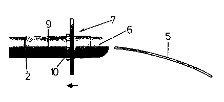
body. According to the illustration of Figure 7, after
this procedure, the plans 6 is exposed and can be
hygienically treated or disinfected. As further
indicated in Figure 7, catheterization by means of a
catheter 5 is possible after exposing plans 6 and
treating it hygienically.
Figure 8 shows a subsequent situation, in
which the expanding attachment 7 is again pulled
forward over the plans 6, with the orifice 1 however
remaining still stretched by means of expanding fingers
10. By actuating the expanding attachment 7, the
CA 02297217 2000-O1-26
13
expanding fingers 10 move toward the center, thereby
relieving the condom 2 in the region of orifice 1.
After a total retraction of the expanding fingers
according to Figure 9, it is possible to remove the
expanding attachment 7, as shown in Figures 9 and 10,
so that it is possible to reinsert the connector 4 with
urine drainage hose 8 into orifice 1 and to secure it
there in leakproof manner, as finally shown in Figure
12.
Figures 13-16 show in detail an embodiment of
an expanding attachment 7, wherein the previously
mentioned expanding fingers 10 are coaxially arranged
in an annular shape. To stretch orifice 1 of the
condom 2, it i~ possible to move expanding fingers 10
apart from one another to a larger radius, as shown in
particular in Figures 15 and 16. Figures 13 and 16
show jointly that the expanding fingers 10 can be moved
apart from and toward one another in the fashion of a
diaphragm.
As can be noted from Figures 14 and 16, the
expanding fingers extend orthogonally from the
expanding attachment 7, and are jointed to the
expanding attachment by means of a lever arrangement.
Concretely, each expanding finger 10 is stationarily
connected to a pivoting lever arm 11, with the lever
arrangement ard, thus, the lever arms 11 extending
between two annular disks 12, and the annular disks 12
oppositely engaging guide elements 13, and being
interconnected for rotation.
Figures 13-16 show especially clearly that
the lever arms 11 are pivotally jointed to one of the
annular disks 12 and guided on the other annular disk
12 by guide elements, which are pins 14 that engage
guide slots 15 in lever arms 11.
CA 02297217 2000-O1-26
14
By oppositely rotating annular disks 12, the
lever arms 11 are pivoted, thereby displacing in turn
expanding fingers 10 from an annular arrangement with a
small radius, as shown in Figures 13 and 14, to an
annular arrangement with a larger radius, as shown in
Figures 15 and 16, and vice versa.
As further indicated in Figures 13-16, each
annular disk 12 comprises an eye 17 jointed to its
outer edge 16 for actuating the expanding attachment 7
in the fashion of scissors. With the eyes 17 spaced
apart as shown: in Figures 13 and 14, the expanding
fingers 10 are in their inner position. With abutting
eyes 17, as shown in Figures 15 and 16, the expanding
fingers 10 are moved apart from one another for
stretching orifice 1.
Figures 17, 18, and 19 show in detail a
further, essential part of the device according to the
invention, namely connector 4 which is used for
connecting to the urine collector not shown. This
connector 4 comprises an insertion member 18 that can
be inserted through orifice 1 to come to lie against
the inside wall of condom 2 around orifice 1, and a
clamping member 19 that can be pressed from the outside
against insertion member 18. The clamping member 19
can be pressed against insertion member 18 under the
bias of an elastic force. Such an arrangement is
omitted in Figures 17-19 for the sake of simplicity.
As jointly shown in Figures 17 and 18, the
insertion member 18 comprises on the insertion side a
contact surface that conically widens toward the free
end for contacting the inside wall of condom 2, and the
clamping member 19 has a clamping edge 21, which may
here be an approximately complementary clamping
surface. In the selected embodiment, the clamping edge
" CA 02297217 2000-O1-26
IS
21 serves to clamp the edge region around the orifice
1.
As further shown in Figures 18 and 19, the
insertion member 18 comprises a lead-in nose 22, which
facilitates entering or inserting the insertion member
18 into orifice 1 due to its noselike configuration.
As furthermore jointly shown in Figures 17
and 18, the insertion member 18 comprises on its
connection side a connection adapter 23 for receiving
the hose 8 that leads to the urine collector not shown.
Finally, as can be noted from Figures l7-19,
the clamping member 19 is slid onto insertion member
18. Against the force of an elastic means not shown,
it is possible to move the clamping member 19 away from
its clamping position on contact surface 20. To this
end, the connector 4 comprises an actuating element 24
for releasing or actuating clamping member 19. As
regards further details, the general description of the
specification is herewith incorporated by reference for
purposes of avoiding repetitions.
Lastly, it should quite explicitly be
referred to the fact that the foregoing embodiment
serves only t~ explain the claimed teaching, but
without limiting same to the embodiment.