Note : Les descriptions sont présentées dans la langue officielle dans laquelle elles ont été soumises.
CA 02298148 2005-05-02
66239-1836D
1
CONVEYABLE COVER FORMER AND FASTENING SYSTEM
BACKGROUND
The present invention relates to an apparatus and
method for using a conveyable cover former for placing a
cover about an article, conveying the covered article to a
fastening device, and applying a fastener about the covered
article, and more particularly, but not by way of
limitation, to such apparatus and methods wherein the
article is a potted plant or flower pot.
SUMMARY
In accordance with the present invention, there is
provided a method for processing an article, comprising:
providing a cover forming apparatus; placing a sheet of
material in a cover forming position adjacent the cover
forming apparatus; positioning an article in a position
adjacent the sheet of material; forming the sheet of
material into a cover about an outer peripheral surface of
the article using the cover forming apparatus; conveying a
conveyable fastener applicating apparatus via a conveying
apparatus to a fastening position adjacent the cover forming
apparatus; automatically applying a fastener about a portion
of the cover of the article thereby fastening the cover
about the article; and removing the article.
In accordance with another aspect of the
invention, there is provided a method for processing an
article, comprising: providing the article; providing a
sheet of material; forming the sheet of material about the
article at a forming station; providing a conveyable
fastener applicating device at a position remote from the
forming station; moving the conveyable fastener applicating
device from the position remote from the forming station to
CA 02298148 2005-05-02
66239-1836D
la
a fastener applicating position; and automatically applying
a fastener via the fastener applicating device about a
portion of the sheet of material formed about the article.
In accordance with a further aspect of the
invention, there is provided an apparatus for processing an
article, comprising: a cover forming apparatus adapted to
form a sheet of material into a cover about a potted plant;
a conveyable fastener applicating apparatus for
automatically applying a fastener about a portion of an
outer surface of a cover formed about the article by the
cover forming means; a conveying apparatus for conveying the
conveyable fastener applicating apparatus to a fastener
applicating position; and a drive apparatus for conveying
the conveyable fastener applicating apparatus via the
conveying apparatus to the fastener applicating apparatus.
The invention satisfies the need for rapidly
covering and fastening the cover about an article with a
minimal amount of manual effort and in a location having a
limited amount of available space.
CA 02298148 2000-02-28
' 2
The apparatus may further comprise conveying
assembly or rail for conveying the covered article and
conveyable cover forming assembly or mold from the cover
forming position to a fastener application positioning at the
fastening or tying device.
The apparatus may also comprise a labeling device
for automatically applying a label to a pbrtion of the outer
surface of the cover of the covered article. The apparatus
may further comprise an assembly for automatically placing a
sheet of material on the support surface.
The present invention also relates to a method for
processing an article. The process initially comprises
providing a platform having a support surface formed thereon
and an opening extending through the support surface. The
opening is as described above. The conveyable cover forming
assembly or mold has contacting portions and is sized to
receive an article, which may be a flower pot. The next step
is placing a sheet of material in a cover forming position
over the opening and on the support surface wherein the sheet
of material, in the cover forming position, is positioned over
the conveyable cover forming assembly or mold.
The next step is providing the article and
positioning the article in a position over the sheet of
material so the article is disposed generally above and near
the portion of the sheet of material which is above the
conveyable cover forming assembly or mold. Then, the article
is moved in a direction which causes the lower end of the
article to engage a portion of the sheet of material. The
article and portions of the sheet of material pass into the
conveyable cover forming assembly or mold causing the sheet
of material to contact or nearly contact both the outer
peripheral surface of the article and the contacting portions
of the conveyable cover forming assembly. The sheet is pressed
about the outer peripheral surface of the article to form a
cover about the article.
The conveyable cover forming assembly or mold is
automatically conveyed on a conveying assembly such as a rail
so that the covered article is moved into a fastener
applicating position at the fastening device. After the
CA 02298148 2000-02-28
3
covered article is conveyed to the fastener applicating
position a fastener is automatically applied about a portion
of the outer surface of the cover of the article for fastening
the cover about the article. Then the covered article is
removed from the conveyable cover forming assembly. The
covered article may be removed before or after the conveyable
cover forming assembly is returned via the conveying assembly
to near the platform. Also, the method may comprise the
additional step of engaging an automatic labeling means and
automatically applying a label to a portion of the outer
surface of the cover of the article prior to the removal of
the covered article.
DESCRIPTION OF THE DRAWINGS
Figure 1 is a plan view of a first sheet of material
with one end turned up and constructed in accordance with the
present invention.
Figure 2 is a plan view of a second sheet of
material with one end turned up and constructed in accordance
with the present invention.
Figure 3 is a perspective view showing the first and
the second sheets of material disposed adjacent each other.
Figure 4 is a perspective view showing bonding areas
on the surface of a first sheet or a second sheet which cause
bonding of the second sheet and the first sheet.
Figure 5 is a sectional view of a modified first and
second sheets of material.
Figure 6 is another cross-sectional view of a
modified first sheet of material connected to a modified
second sheet of material.
Figure 7 is a cross sectional view of still another
modified first sheet of material connected to a modified
second sheet of material.
Figure 8 is another cross-sectional view of yet
another modified first sheet of material connected to a
modified second sheet of material.
Figure 9 is a diagrammatic view of a plurality of
sheets of material, constructed in accordance with the present
CA 02298148 2000-02-28
4
invention forming a continuous roll, the roll partially
unrolled to reveal a single sheet still attached thereto.
Figure l0 is a diagrammatic view of a plurality of
sheets of material forming a continuous roll of material
disposed in a dispenser.
Figure 11 is a diagrammatic view showing a roll of
material wherein the roll of material cc3mprises a first and
a second sheet of material constructed in accordance with the
present invention disposed in a dispenser (diagrammatically
shown in Figure 11) for dispensing the first and the second
sheets of material from the roll of material.
Figure 12 is a diagrammatic view of a roll of
material for dispensing a first and a second sheet of material
constructed in accordance with the present invention from the
roll of material.
Figure 13 is a side elevational view of a pad of
first and second sheets of material constructed in accordance
with the present invention.
Figure 14 is a plan view of a sheet of material with
a sheet extension connected thereto constructed in accordance
with the present invention.
Figure 15 is a plan view showing the upper surface
of another sheet of material with a sheet extension connected
thereto constructed in accordance with the present invention.
Figure 16 is a perspective view of a pre-formed
decorative pot cover.
Figure 17 is a side elevational view of a tying
assembly of the present invention.
Figure 18 is a plan view of the tying assembly of
Figure 17.
Figure 19A is a perspective view of a cover forming
mold of Figure 17.
Figure 19B is a perspective view of another version
of a cover.. forming mold of Figure 17.
Figure 20 is a side elevational view of a version
of the present invention having a material dispenser.
Figure 21 is a plan view of the version of the
present invention shown in Figure 20.
CA 02298148 2005-05-02
66239-1836D
Figure 22A-22D are side elevational views of the
apparatus of Figure 17 while in operation.
Figure 23 is a side view of a potted plant having
a cover fastened thereto.
5 Figure 24 is a side view of a potted plant having
a cover fastened thereto, the cover having a sheet
extension.
DESCRIPTION
As described herein, in one version, the present
invention comprises an apparatus for processing an article
such as a potted plant or flower pot. The apparatus
comprises a platform supported by a framework. The platform
has a support surface formed thereon and an opening
extending through the support surface. The opening is sized
to accommodate an article to be passed therethrough. The
article has an upper end, a lower end, and an outer
peripheral surface.
The apparatus further comprises a conveyable cover
forming assembly having contacting portions and a receiving
end and sized to receive the article. The cover forming
assembly is further adapted such that the sheet of material
is formed into a cover about the outer peripheral surface of
the article when the article is moved in a direction which
causes the lower end of the article to engage a portion of
the sheet of material. As the sheet is engaged, the article
and portions of the sheet of material pass into the
receiving end of the conveyable cover forming assembly
causing the sheet of material to contact or nearly contact
both the outer peripheral surface of the article and the
contacting portions of the conveyable cover forming
assembly. As the article is moved the sheet is pressed
CA 02298148 2005-05-02
66239-1836D
6
about the outer peripheral surface of the article to form
the cover about the article. The cover has an inner surface
facing the outer peripheral surface of the article and an
exposed outer surface.
The apparatus further comprises a conveying
assembly for conveying the conveyable cover forming assembly
from adjacent the platform to a fastener applicating
position. The apparatus further comprises a fastener
applicating device such as a tying device for automatically
applying a fastener about a portion of the outer surface of
the cover of the article for fastening the cover about the
article when the conveyable cover forming assembly is
conveyed via the conveying assembly to the fastener
applicating position.
Finally, the apparatus comprises a drive assembly
for conveying the conveyable cover forming assemblies via
the conveying assembly to the fastener applicating position
adjacent the fastener applicating device and for returning
the conveyable cover forming assembly via the conveying
assembly to a cover forming position adjacent the platform.
Optionally, the apparatus may further comprise a labeling
device for automatically applying a label to a portion of
the outer surface of the cover of the covered article.
The present invention further comprises a method
using the apparatus described above for processing an
article such as a potted plant or flower pot. The method
comprises the first step of providing a platform having a
support surface formed thereon and an opening extending
through the support surface in which the opening is sized to
accommodate an article passed therethrough. In the next
step is provided a conveyable cover forming assembly, such
CA 02298148 2005-05-02
66239-1836D
7
as described above, which is conveyable via a conveying
assembly such as a rail.
Next, a sheet of material is placed in a cover
forming position over the opening and on the support surface
wherein the sheet of material, in the cover forming
position, is positioned over the receiving end of the
conveyable cover forming assembly. An article, for example
a potted plant or flower pot, is provided. The article is
positioned in a position over the sheet of material and in a
position wherein the lower end of the article is disposed
generally above and near the portion of the sheet of
material which is above the receiving end of the conveyable
cover forming assembly.
The sheet of material is formed into a cover about
the outer peripheral surface of the article by moving the
article in a direction which causes the lower end of the
article to engage a portion of the sheet of material whereby
the article and portions of the sheet of material pass into
the receiving end of the conveyable cover forming assembly
causing the sheet of material to contact or nearly contact
both the outer peripheral surface of the article and the
contacting portions of the conveyable cover forming assembly
as the article is moved. The sheet is pressed about the
outer peripheral surface of the article to form the cover
about the article.
A fastener applicating device such as a tying
device is provided. The conveyable cover forming assembly
is conveyed via the conveying assembly from adjacent the
platform to a fastening position adjacent the fastener
applicating device. A fastener is automatically applied
about a portion of the outer surface of the cover of the
CA 02298148 2005-05-02
66239-1836D
7a
article for fastening the cover about the article. The
article with the cover fastened thereabout is then removed.
The present invention, as will be understood by
one of ordinary skill in the art, may also be modified such
that the tying machine is conveyable to a stationary cover
forming apparatus.
That is to say, instead of the cover forming
apparatus being moveable and the tying machine (fastener
applicating device) being stationery as described with
reference particularly to Figures 17, 18, 20, 21 and 22A
to 22D, the opposite is true and the fastener applicating
device is conveyed by the conveying assembly to a location
adjacent the cover forming apparatus where tying takes
place.
It is this modification which the present
application is specifically directed to protecting.
The Embodiments of Fiaures 1-3
Shown in Figure 1 and designated therein by the
general reference numeral 10 is a sheet of material. The
sheet of material 10 has a first end 12, a second end 14, a
first side 16, a second side 18, an upper surface 20 and a
lower surface 22.
A closure bonding material 24 may be disposed on
the upper surface 20 of the sheet of material,
alternatively, the sheet of material 10 may be free of a
closure bonding material. As shown in Figure 1, the closure
bonding material 24, if present, may be disposed adjacent
the first side 16 of the sheet of material 10 and extends
between the first and the second ends 12 and 14 of the sheet
of material 10 or it may be disposed on any other portion of
CA 02298148 2005-05-02
66239-1836D
7b
the sheet 10. As shown in Figure 1, the closure bonding
material 24 is disposed on the upper surface 20 in a strip
of closure bonding material 24, although the closure bonding
material 24 also could be applied to the upper surface 20 of
the sheet of material 10 in the form of spaced apart spots
or the closure bonding material 24 also could be disposed on
the upper surface 20 of
CA 02298148 2000-02-28
8
the sheet of material 10 in any other geometric form and in
any pattern including covering the entire upper surface 20 of
the sheet of material 10. In this last-mentioned instance,
the closure bonding material and the connecting bonding
material would be contained within the bonding material
covering the sheet of material 10. The term "spot" or "spots"
includes any geometric.shape of spot including, but not
limited to, what is commonly referred to as strips.
The sheet of material 10 has a thickness in a range
l0 from about 0.1 mils to about 30 mils. Preferably, the sheet
of material 10 has a thickness in a range from about 0.1 mils
to about 5 mils.
The sheet of material 10 may be any shape and a
square or rectangular shape is shown in Figure 1 only by way
of example. The sheet of material 10 for example only may be
square, rectangular, circular or any other geometric shape
such as heart shaped, for example only.
The sheet of material 10 may be constructed of a
single layer of material or a plurality of layers of the same
or different types of materials. Any thickness of the sheet
of material 10 may be utilized in accordance with the present
invention as long as the sheet of material l0 is wrappable
about an object, such as a plant or flower pot, as described
herein. The layers of material comprising the sheet of
material 10 may be connected together or laminated or may be
separate layers.
Shown in Figure 2 is a second sheet of material 26.
The second sheet of material 26 has a first end 28, a second
end 30, a first side 32, a second side 34, an upper surface
36 and a lower surface 38. The second sheet of material 26,
if used may be constructed of paper. The term "paper" as used
herein means treated or untreated paper, corrugated paper or
cardboard or any other form of paper material.
The fi-rst sheet of material 10 has a length 40
extending between the first and the second sides 16 and 18 of
the sheet of material 10. The first sheet of material 10 also
has a width 42 extending between the first and the second ends
12 and 14 of the first sheet of material 10.
CA 02298148 2000-02-28
9
The second sheet of material 26 has a length 44
extending between the first and the second sides 32 and 34 of
the second sheet of material 26. The second sheet of material
26 has a width 46 extending between the first and the second
ends 28 and 30 of the second sheet of material 26. In a
preferred embodiment, the length 44 of the second sheet of
material 26 is less than the length 40 of~'the first sheet of
material 10 as shown in Figure 3 so that, when the first sheet
of material 10 is disposed adjacent the second sheet of
material 26, a portion of the first sheet of material 10
adjacent the first side 16 thereof extends a distance beyond
the first side 32 of the second sheet of material 26, in a
manner and for reason which will be described in greater
detail below.
The f first sheet of material has a thickness in a
range from about 0.5 mils to about 30 mils and preferably the
thickness of the first sheet of material is in a range from
about 0.5 mils to about 10 mils. The first sheet of material
10 is constructed of a material which is flexible.
2o The second sheet of material 26 has a thickness in
a range from about 0.1 mils to about 30 mils and preferably
in a range from about 0.1 mils to about 10 mils. The second
sheet of material 26 is flexible, but relatively rigid
compared to the first sheet of material 10.
The second sheet of material 26 may be any shape and
a square or rectangular shape is shown in Figure 2 only by way
of example. The second sheet of material for example only may
be square, rectangular, circular ar any other geometric shape.
The second sheet of material 26 may be constructed
of a single layer of materials or a plurality of layers of the
same or different types of materials. Any thickness of the
second sheet of material 26 may be utilized in accordance with
the present invention as long as the second sheet of material
26 is wrappable about an object such as a flower pot, as
described herein, and as long as the second sheet of material
26 provides the rigidity described herein or the absorbency
described herein or both. The layers of material comprising
the second sheet of material 26 may be connected together or
laminated or may be separate layers.
CA 02298148 2000-02-28
In operation, when a second sheet of material 26 is
desired in addition to the first sheet of material 10, the
second sheet of material 26 is placed adjacent the first sheet
of material l0 as shown in Figure 3. In this position, the
5 lower surface 38 of the second sheet of material 26 is
disposed adjacent the upper surface 20 of the first sheet of
material 10. The width 42 of the first sYieet of material 10
is about equal to the width 46 of the second sheet of material
26 so that, when the first and the second sheets of material
10 10 and 26 are disposed adjacent each other, the first end 28
of the second sheet of material is generally aligned with the
first end 12 of the first sheet of material 10, the second end
30 of the second sheet of material 26 is generally aligned
with the second end 14 of the first sheet of material 10, the
second side 18 of the first sheet of material 10 is generally
aligned with the second side 34 of the second sheet of
material and the f first side 16 of the f first sheet of material
10 extends a distance beyond the first side 32 of the second
sheet of material 26 so that the closure bonding material 24
on the upper surface 20 of the first sheet of material 10 is
exposed and not covered by the second sheet of material 26.
It should be noted that the first and the second
sheets of material l0 and 26 each could have virtually
identical lengths 40 and 44. In this case, the second sheet
of material 26 is disposed on the first sheet of material 20
in such a manner that the second side 34 of the second sheet
of material 26 extends a distance beyond the second side 18
of the first sheet of material 10 whereby the first side 16
of the first sheet of material 10 is spaced a distance from
the first side 32 of the second sheet of material 26 thereby
leaving the closure bonding material 24 on the first sheet of
material 10 exposed and not covered by the second sheet of
material 26. And multiple sheets of material 10 and 26 may
be used. Moreover, when multiple sheets of material 10 and
26 are used in combination, the sheets of material 10 and 26
need not be uniform in size or shape. Finally, it will be
appreciated that the sheets of material 10 and 26 shown in all
embodiments herein are substantially flat.
CA 02298148 2000-02-28
11
As noted earlier, a closure bonding material may be
disposed on the upper surface of the first sheet of material
10. The closure bonding material 24 may be applied as a strip
or as spots or other shapes. One method for disposing a
closure bonding material, in this case an adhesive, is
described in U.S. Patent No. 5,111,637 entitled "Method For
Wrapping A Floral Grouping" issued to Wedef' et al. , on May 12,
1992 ,
The first sheet of material 10 can be utilized alone
or in combination with the second sheet of material 26 to wrap
a potted plant or flower pot. The term "flower pot" refers
to any type of container used for holding a floral grouping
or a potted plant. Examples of flower pots used in accordance
with the present invention are clay pots, plastic pots, and
the like. "Floral grouping" as used herein means cut fresh
flowers, artificial flowers, a single flower other fresh
and/or artificial plants or other floral materials and may
include other secondary plants and/or ornamentation or
artificial or natural materials which add to the aesthetics
of the overall floral arrangement. The floral grouping
comprises a bloom or foliage portion and a stem portion.
However, it will be appreciated that the floral grouping may
consist of only a single bloom or only foliage (not shown).
The term "floral grouping" may be used interchangeably herein
with the term "floral arrangement".
The first sheet of material 10 or the second sheet
of material 26 may be constructed of a single layer of
material or a plurality of layers of the same or different
types of materials. Any thickness of the sheet of material
10 or 26 may be utilized in accordance with the present
invention as long as the sheet of material 10 or 26 flay be
wrapped or formed about at least a portion of a portion of a
flower pot, as described herein. Additionally, an insulating
material such as-bubble film, preferable as one of two or more
layers, can be utilized in order to provide additional
protection for the item wrapped therein.
In a preferred embodiment, the first sheet of
material 10 is constructed from two polypropylene films (a 20"
x 15" sheet of Mobil 270 ABW white opaque film laminated to
CA 02298148 2000-02-28
12
a 20" x 15" sheet of Mobil 22o AB clear film) having a
thickness in a range of from less than about 1.0 mil to about
2.5 mils. The layers of material comprising the first sheet
of material l0 may be connected together or laminated or may
be separate layers.
The sheet of material 10 is constructed from any
suitable wrapping material that is capably of being wrapped
about a flower pot or floral grouping, as the case may be.
Preferably, the wrapping material l0 comprises paper
(untreated or treated in any manner), cellophane, foil,
polymer film, fabric (woven or nonwoven or synthetic or
natural), burlap, or combinations thereof.
The term "polymer film" means a man-made polymer
such as a polypropylene or a naturally occurring polymer such
as cellophane. A polymer film is relatively strong and not
as subject to tearing (substantially non-tearable), as might
be the case with paper or foil.
The sheet of material 10 or 26 may vary in color.
Further, the sheet of material l0 or 26 may consist of designs
or decorative patterns which are printed, etched, and/or
embossed thereon using inks or other printing materials. An
example of an ink which may be applied to the surface of the
sheet of material l0 or 26 is described in U.S. Patent No.
5,147,706 entitled "Water Based Ink On Foil And/Or synthetic
organic polymer" issued to Kingman on Sep. 15, 1992.
In addition, the
sheet of material l0 or 26 may have various colorings,
coatings, flocking and/or metallic finishes, or other
decorative surface ornamentation applied separately or
3o simultaneously or may be characterized totally or partially
by pearlescent, translucent, transparent, iridescent or the
like, qualities. Each of the above-named characteristics may
occur alone or in combination and may be applied to the upper
and/or lower surface of the sheet of material 10 or 26.
Moreover, each surface of the sheet of material 10 or 26 may
vary in the combination of such characteristics. The sheet
of material 10 or 26 itself may be opaque, translucent or
partially clear or tinted transparent.
CA 02298148 2000-02-28
13
Embodiments of Figures 4-8
Referring now to Figure 4, a bonding material may
be applied to either the upper surface of a first sheet of
material l0a or to the lower surface of a second sheet 26a of
material in a plurality of patches 48 for the purpose of
bonding the upper surface of the first sheet l0a to the lower
surface of the second sheet 26a.
Shown in Figure 5 is a modified first sheet of
material lOb connected to a modified second sheet of material
26b. The first sheet of material lOb is constructed exactly
like the sheet of material 10. The second sheet of material
26b is constructed like the sheet of material 26 described in
detail before and shown in Figure 2, except the second sheet
of material 26b includes a bonding material 60 disposed on the
lower surface 38b of the second sheet of material 26b. The
bonding material 60 is in the form of a plurality of spaced
apart spots of bonding material 60, similar to that shown in
Figure 4. The lower surface 38b of the second sheet of
material 26b is bondingly connected to the upper surface 20b
of the first sheet of material lOb by way of the bonding
material 60. Since the bonding material 60 is in the form of
a plurality of spaced apart spots, a plurality of spaced apart
spaces 62 (only one of the spaces 62 being designated by
reference numeral in Figure 5) are formed between the lower
surface 38b of the second sheet of material 26b and the upper
surface 20b of the first sheet of material lOb. The spaces
62 provide air gaps which form an insulation when the first
and the second sheets of material 10b and 26b are wrapped
about a flower pot in a manner and for reasons like that
described herein.
Shown in Figure 6 is a modified first sheet of
material lOc connected to a modified second sheet of material
26c. The first sheet of material lOc is constructed exactly
like the sheet of material l0 shown in Figure 1, except the
first sheet of material lOc includes a bonding material 64
disposed on the upper surface 20c of the first sheet of
material lOc. The bonding material 64 is in the form of a
plurality of spaced apart spots of bonding material 64,
similar to that shown in Figure 5. The lower surface 38c of
CA 02298148 2000-02-28
14
the second sheet of material 26c is bondingly connected to the
upper surface 20c of the first sheet of material lOc by way
of the bonding material 64. Since the bonding material 64 is
in the form of a plurality of spaced apart spots, a plurality
of spaces 66 (only one of the spaces 66 being designated by
a reference numeral in Figure 6) are formed between the lower
surface 38c of the second sheet of material 26c and the upper
surface 20c of the first sheet of material lOc. The spaces
66 provide air gaps which form an insulation when the first
and the second sheets of material lOc and 26c are wrapped
about a flower pot in a manner and for reasons like that
described herein in connection with Figure 5.
Shown in Figure 7 is a modified first sheet of
material lOd connected to a modified second sheet of material
26d. The first sheet of material lOd is constructed exactly
like the sheet of material shown in Figure 1, except the first
sheet of material lOd includes a bonding material 68 on the
upper surface 20d thereof. The second sheet of material 26d
is constructed exactly like the second sheet of material 26
shown in Figure 2, except the second sheet of material 26d
includes a plurality of spaced apart raised portions 70. The
raised portions 70 may be formed by embossing the second sheet
of material 26d or forming corrugations in the second sheet
of material 26d or in any other manner desired in any
particular application.
The upper surface 20d of the first sheet of material
lOd is disposed generally adjacent the lower surface 38d of
the second sheet of material 20d or, more particularly,
adjacent the raised portions 70 on the second sheet of
material 26d. In this position, the raised portions 70 are
bonded to the upper surface 20d of the first sheet of material
lOd by way of the bonding material 68 to connect the first
sheet of material lOd to the second sheet of material 20d.
The spaced apart raised portions 70 on the second
sheet of materia-1 26d form a plurality of spaces 72 between
the first sheet of material lOd and the second sheet of
material 26d in a connected position of the first and the
second sheets of material lOd and 26d for providing insulation
when the first and second sheets of material lOd and 26d are
CA 02298148 2000-02-28
connected together and wrapped about a flower pot in a manner
like that described herein.
Shown in Figure 8 is a modified first sheet of
material l0e connected to a modified second sheet of material
5 26e. The first sheet of material l0e is constructed exactly
like the sheet of material 10 shown in Figure l, except the
first sheet of material.l0e includes a plurality of spaced
apart raised portions 74. The raised portions 74 may be
formed in the first sheet of material l0e by embossing the
10 first sheet of material l0e or forming corrugations in the
first sheet of material l0e or in any other suitable manner.
The second sheet of material 26e is constructed exactly like
the second sheet of material 26 shown in Figure 2, except the
second sheet of material 26e includes a bonding material 76
15 disposed on the lower surface 38e thereof.
In operation, the upper surface 20e of the first
sheet of material l0e is disposed generally adjacent the lower
surface 38e of the second sheet of material 26e or, more
particularly, the raised portions 74 on the first sheet of
material l0e are disposed adjacent the lower surface 38e of
the second sheet of material 26e. In this position, the first
sheet of material l0e is bondingly connected to the second
sheet of material 26e by way of the bonding material 76 on the
second sheet of material 26e or, more particularly, the
bonding material 76 on the second sheet of material 26e
bondingly engages and bondingly connects to the raised
portions 74 on the first sheet of material l0e to connect the
first sheet of material l0e to the second sheet of material
26e. In this connected position of the first sheet of
material loe and the second sheet of material 26e, the raised
portions 74 cooperate to form a plurality of spaces 76.
Between the first sheet of material l0e and the second sheet
of material 26e. The spaces 76 cooperate to provide an
insulation when the first and the second sheets of material
l0e and 26e are wrapped about a flower pot in a manner and for
reasons like that described herein.
Embodiments of Figures 9-10
CA 02298148 2000-02-28
16
Referring now to Figure 9, a plurality of individual
sheets of material lOf are connected linearly together to form
a roll 80. Preferably, the plurality of sheets of material
lOf in the roll 80 are connected by perforations 82, as
illustrated in Figure 9. Such a roll 80 permits one sheet of
material lOf to be withdrawn from the roll 80, then severed
or disconnected from the.roll 80. Alternatively, as shown in
Figure 10, the roll 80 may simply be formed as a continuous
roll 80 of wrapping material without perforations, wherein a
plurality of sheets of material lOf may be removed from the
roll 80 by unrolling a portion of the roll 80, and using a
separate cutting element (not shown) to sever the unrolled
portion of the roll 80 of material to form the sheet of
material lOf . The roll 80 may also be contained within a
dispenser:84, as illustrated in Figure 10. When the roll 80
is disposed in the dispenser 84, a portion of the wrapping
material is again unrolled, and a serrated cutting edge 86
contained within the dispenser 84, or a separate cutting
element (not shown), severs the unrolled portion of the
wrapping material from t2~e roll 80 to form a sheet of material
lOf. Any number of sheets of material lOf may form the roll
80 as long as it is possible to withdraw at least one sheet
lOf from the roll 8o as described herein.
Embodiments of FiQUres 11-12
The first and the second sheets of material
described herein can be provided in the form of a roll of
first and second sheets of material wherein the first and the
second sheets of material are unrolled from the roll of first
and second sheets of material and the first and the second
sheets of material are severed from the roll either by
perforations at spaced apart locations in the roll or by
cutting the first and the second sheets of material from the
roll. It also should be noted that additional sheets of
material may be combined with the first and the second sheets
of material if so desired in a particular application.
Shown in Figure 11 is a roll of material 90
comprising a first material 92 and a second material 94 with
CA 02298148 2000-02-28
17
the second material 94 being disposed adjacent the first
material 92. The first material 94 is constructed of any of
the materials described before with respect to the first sheet
of material. The second material 94 is constructed of any of
the materials described before with respect to the second
sheet of material.
The roll of material 90 is dispdsed in a dispenser
96 having an opening 98 through which the materials 92 and 94
may be withdrawn from the roll of material 90. A cutting edge
100 is disposed on the dispenser 96 near the opening 98. The
cutting edge 100 may be a sawtooth type of edge, as shown in
Figure 11, or the cutting edge 100 may be any other type of
edge or device suitable for cutting a portion of the materials
92 and 94 from the roll of material 90 and the cutting edge
100 may be connected to the dispenser 96 or may be a separate
component if desired in particular application.
The roll of material 90 has a leading edge 102. In
operation, the leading edge 102 is gripped or a portion of the
first and/or the second materials are gripped and the first
and the second materials are unrolled and withdrawn from the
roll of material 90 in a direction 104. The first and the
second materials 92 and 94 are withdrawn or unrolled from the
roll of material 90 until a desired length of the first and
the second materials 92 and 94 have been withdrawn from the
roll of material 90. In this position, a portion of the first
and the second materials 92 and 94 are disposed adjacent the
cutting edge 100. The first and the second materials 92 and
94 then are maneuvered to pass the first and the second
materials 92 and 94 over the cutting edge 100 thereby severing
a portion of the material extending a distance from the
leading edge 102 thereof from the roll of material 90. The
portion of the first and the second materials 92 and 94
withdrawn from the roll of material 90 and severed from the
roll of material 90 comprise the first and the second sheets
of material as described herein.
The first and the second materials 92 and 94 in the
roll of material 90 may be connected or unconnected. Further,
the roll of material 90 may comprise two rolls of material
with one of the rolls of material comprising the first
CA 02298148 2000-02-28
18
material 92 and the other roll of material comprising the
second material 94. In this last-mentioned embodiment, the
first material 92 is withdrawn from the first roll of material
and the second material 94 is withdrawn from the second roll
of material about simultaneously so that the first and the
second materials 92 and 94 are provided in a manner as
generally shown in Figure 11 for severincj from the first and
second rolls of material to provide the first and the second
sheets of material as described herein. The term "roll of
material" as used herein is intended to encompass two or more
rolls in the manner generally described.
Shown in Figure 12 is a modified roll of material
90a comprising a first material 92a and a second material 94a
with a leading edge 102a. The roll of material 90a is
constructed exactly like the roll of material 90 described
before, except the roll of material 90a is not disposed in a
dispenser constructed like the dispenser 96 shown in Figure
11. Rather, the roll of material 90a is supported on a
generally mounted shaft 106. The first and the second sheets
of material 92a and 94a are withdrawn from the roll of
material 90a in a manner like that described before in
connection with Figure 11 until a predetermined length of the
first and the second materials 92a and 94a have been withdrawn
from the roll of material 90a. In this position, a portion
of the first and the second materials 92a and 94a are disposed
under a knife edge 108. The knife edge 108 is connected to
an actuator 110 adapted to move the knife edge 108 in a
direction 112 and in a direction 114. When the predetermined
length of the first and the second materials 92a and 94a have
been withdrawn from the roll of material 90a, the actuator 110
actuates to move the knife edge 108 in the direction 112 to
a position wherein the knife edge 108 severingly engages the
materials 92a and 94a to severingly cut a portion of the first
and the second materials 92a and 94a from the roll of
materials 90a to-provide the first and the second sheets of
material as described herein. The actuator 110 may comprise
a hydraulic or pneumatic cylinder or a motor and gear
arrangement or any other form of arrangement suitable for
moving the knife edge 108 in the directions 112 and 114.
CA 02298148 2000-02-28
19
After the knife edge 108 has cuttingly severed the desired
portion of the first and the second sheets of material 92a and
94a from the roll of material 90a, the actuator 110 is
actuated to move the knife edge 108 in the direction lI4 to
a storage position disposed a distance above the first and the
second materials 92a and 94a as opposed to the cutting
position previously described.
Embodiment of Ficrure 13
Shown in Figure 13 is a pad 116 of first sheets of
materials designated by the reference numerals lOf, lOg, and
10h in Figure 13 and a plurality of second sheets of material
designated in Figure 13 by the reference numerals 26f, 26g and
26h. The first sheets of material lOf, lOg and IOh may be
constructed like the sheet of material to shown in Figure 1
and described in detail before and the second sheets of
material 26f, 26g and 26h may be constructed like the second
sheet of material 26 shown in Figure 2 and described in detail
before, or like any of the other first and the second sheets
of material described herein. The first and the second sheets
of material lOf, lOg, lOh, 26f, 26g and 26h are connected in
the form of a pad 116 with the closure bonding material 24f,
24g and 24h cooperating to connect the first sheets of
material lOf, lOg and lOh in the form of the pad 116. The
second sheets of material 26f, 26g and 26h may be connected
to the respective first sheets of material lOf, lOg and lOh
or may be interleaved between the adj acent first sheets of
material lOf, lOg and lOh in the pad 116. In the alternative,
the second sheets of material 26f, 26g and 26h may be
connected to form the pad 116 with the first sheets of
material lOf, lOg and lOh being interleaved in the respective
second sheets of material 26f, 26g and 26h and/or connected
thereto. In operation, one of the first sheets of material
lOf, lOg or lOh along with the adjacent second sheet of
material 26f, 26g and 26h may be removed from the pad 116 and
then placed in position to be wrapped about the flower pot.
Embodiments of Figures 14-16
CA 02298148 2000-02-28
As noted above, a first sheet of material 10 or a
first sheet 10 and a second sheet of material 26 may be used
to provide a decorative cover for an object such as a f lower
pot or a potted plant. To cover the object, the sheet or
5 sheets may be manually or automatically placed in a position
to be formed about the outer peripheral surface of the pot or
potted plant as described~in more detail below. Or, the sheet
or sheets may be formed into a preformed cover which ~.s then
placed in a position to receive the pot or potted plant using
10 the present invention.
Referring now to Figure 14, as shown therein and
designated by the general reference numeral lOj is another
sheet of material constructed in accordance with the present
invention. The sheet of material lOj shown in Figure 14 has
15 an upper surface 12j, a lower surface 14j, a first end 16j,
a second end 18j , a f first side 20j and a second side 22j . The
ends 16j and 18j cooperate with the sides 20j and 22j to
define an outer peripheral surface 24j of the sheet of
material lOj. The outer peripheral surface 24j of the sheet
20 of material lOj is defined by perforations 26j, as shown in
Figure 14.
As shown in Figure 14, a sheet extension 28j is
connected to the outer peripheral surface 24j of the sheet of
material lOj. The sheet extension 28j extends a distance
outwardly from the outer peripheral surface 24j of the sheet
of material lOj. The sheet extension 28j has a first end 30j,
a second end 32j, a first side 34j and a second side 36j. A
portion of the sheet extension 28j extends a distance
outwardly from the first end 16j of the sheet of material lOj
terminating with the first end 30j of the sheet extension 28j.
Another portion of the sheet extension 28j extends a distance
outwardly from the second end I8j of the sheet of material lOj
terminating with the second end 32j of the sheet extension
28j. Yet another portion of the sheet extension 28j extends
a distance outwardly from the first side 20j of the sheet of
material lOj terminating with the first side 34j of the sheet
extension 28j. Still another portion of the sheet extension
28j extends a distance outwardly from the second side 22j of
CA 02298148 2000-02-28
21
the sheet of material lOj terminating with the second side 36j
of the sheet extension 28j.
The sheet extension 28j cooperates with the sheet
of material lOj to define a generally square or rectangularly
shaped sheet with the perforations 26j being disposed in a
central portion of the sheet and def fining the outer peripheral
surface 24j of the sheet of material lOj : Preferably, the
sheet of material lOj and the sheet extension 28j are unitary
and formed from a single sheet or plies or multiple sheets one
on top of the other which may or may not be laminated.
The sheet of material lOj and the sheet extension
28j are constructed from any suitable flexible material that
is capable of being wrapped about a flower pot and formed into
the covering, as described herein. Preferably, the sheet of
material lOj and the sheet extension 28j are constructed of
a material selected from a group of materials consisting of
paper, metal foil, cloth (natural or synthetic) , denim, burlap
or polymer film as defined above or combinations thereof.
The sheet of material lOj and the sheet extension
28j have a thickness in a range from about 0.1 mils to about
mils. Preferably, the sheet of material lOj and the sheet
extension 28j have a thickness in a range from about 0.1 mils
to about 5 mils.
The sheet of material lOj and the sheet extension
25 28j may be any shape and a rectangular shape is shown in
Figure 19 only by way of example. The sheet of material lOj
and the sheet extension 28j for example only may be square,
rectangular, circular or any other geometric shape such as
heart shaped for example only.
30 The sheet of material lOj and the sheet extension
28j may be constructed of a single layer of material or a
plurality of layers of the same or different types of
materials. Any thickness of the sheet of material lOj and the
sheet extension 28j may be utilized in accordance with the
present invention as long as the sheet of material lOj and the
sheet extension 28j is wrappable about a flower pot and
formable into the covering, as described herein. The layers
of material comprising the sheet of material lOj and the sheet
CA 02298148 2000-02-28
22
extension 28j may be connected together or laminated or may
be separate layers.
The sheet extension 28j is transparent, although a
decorative pattern also may be applied to the sheet extension
28j .
The sheet extension 28j preferably includes a
bonding material 72j (Figure 14) disposed on the upper surface
of the sheet extension 28j and extending about the outer
peripheral surface of the sheet extension 28j. After the
sheet extension 28j has been formed about the floral grouping,
the ends of the sheet of material may be bonded together to
provide a closed end. The term "bonding material" as used
herein is as defined below.
The sheet extension 28j remains in a position
extending about the floral grouping until it is desired to
remove the sheet extension 28j. The sheet extension 28j is
removed from the pot cover 56j by tearing along the
perforations 26j separating the sheet extension 28j from the
pot cover 56j. The sheet extension 28j then is removed from
the floral grouping 48j leaving the pot cover 56j providing
a decorative cover for the pot 38j.
In addition to the perforations 26j, the sheet
extension 28j also may include perforations extending between
the perforations 26j and the outer peripheral surface of the
sheet extension 28j to further assist in the removal of the
sheet extension 28j when it is no longer desired to keep the
sheet extension 28j extending about the floral grouping.
Shown in Figure 15 and designated by the general
reference number lOk is a sheet of material constructed in
accordance with the present invention. The sheet of material
lOk includes a first end 12k, a second end 14k, a first side
16k and a second side 18k. The sheet of material lOk also
includes an upper surface 20k (Figure 15) and a lower surface
22k (not shown).
A connecting bonding material 24k is disposed on the
upper surface 20k of the sheet of material lOk. The sheet of
material 10k has an outer peripheral surface 26k. The
connecting bonding material lOk is disposed near and spaced
a distance 28k from the outer peripheral surface 26k of the
CA 02298148 2000-02-28
23
sheet of material lOk and extends generally circumferentially
about the sheet of material lOk.
The sheet of material lOk shown in Figure 15 is
circularly shaped and the connecting bonding material 24k
extends in a circularly shaped pattern over the upper surface
20k of the sheet of material lOk. The sheet of material lOk
may be any geometric shape such as square'' or rectangular or
heart shaped or trapezoidally shaped or any other geometric
shape. Further, the connecting bonding material 24k may
extend in any geometric pattern over the upper surface 20k of
the sheet of material lOk, and the circularly shaped pattern
is shown in Figure 15 only by way of example.
A sheet extension 25k is connected to the sheet of
material lOk. The sheet extension 25k extends about the outer
peripheral surface 26k of the sheet of material lOk. The
sheet extension 25k extends outwardly from the sheet of
material 10k terminating with an outer peripheral surface 27k.
The sheet extension 25k has an upper surface 29k (Figure 15)
and a lower surface 31k (not shown). The upper surface 29k
is disposed in a plane about coplanar with the upper surface
22k of the sheet of material lOk and lower surface 31k is
disposed in a plane about coplanar with the lower surface 22k
of the sheet of material lOk.
The sheet extension 25k and the sheet of material
lok may be integrally constructed of a single sheet of
material or the sheet extension 25k may be laminated to the
sheet of material lOk. A connecting bonding material 33k is
disposed on the upper surface 29k of the sheet extension 25k.
The connecting bonding material 33k is disposed near and
spaced a distance from the outer peripheral surface 27k of the
sheet extension 25k and extends generally circumferentially
about the sheet extension 25k.
The sheet extension 25k is shown in Figure 15 as
being circularly shaped. The sheet extension 25k may be any
geometric shape -such as a square or rectangular or heart
shaped or trapezoidally shaped or any other geometric shape
and the geometric shape of the sheet extension 25k may be the
same as the geometric shape of the sheet of material lOk or
the sheet extension 25k may have a geometric shape different
CA 02298148 2000-02-28
24
from the geometric shape of the sheet of material 10k.
Further, although the sheet extension 25k is shown in Figure
15 as extending circumferentially about the outer peripheral
surface 26k of the sheet of material lOk, the sheet extension
25k may extend only about a portion of the outer peripheral
surface 26k of the sheet of material lOk or the sheet
extension 25k may comprise segments With each segment
extending about a portion of the outer peripheral surface 26k
of the sheet of material lOk.
The sheet of material lOk and the sheet extension
25k may be constructed of a single layer of material or a
plurality of layers of the same or different types of
materials as described above. Any thickness of the sheet of
material lOk and the sheet extension 25k may be utilized in
accordance with the present invention as long as the sheet of
material lOk and the sheet extension 25k are wrappable or
formable about a flower pot or a floral grouping in the
manners described herein. The layers of material comprising
the sheet of material lOk and the sheet extension 25k may be
connected together or laminated or may be separate layers.
A decorative pattern, such as a color and/or an embossed
pattern, and/or other decorative surface ornamentation may be
applied to the upper surface 20k and/or the lower surface 22k
of the sheet of material lOk or portions thereof as described
above.
A decorative pattern, such as a color and/or an
embossed pattern, and/or other decorative surface
ornamentation may be applied to the upper surface 29k and/or
the lower surface 31k of the sheet extension 25k or portions
thereof as described above. The sheet extension 25k also may
be totally or partially clear or tinted transparent material
as described above.
The connecting bonding materials 24k and 33k are
shown in Figure 15 as being applied to the upper surface 20k
or the upper surface 29k in the form of a circularly shaped
strip. The connecting bonding materials 24k or 33k may be
applied in the form of spots or spaced apart strips and the
spots may be any geometric pattern or any other type of
pattern such as a logo for example. Further, the connecting
CA 02298148 2000-02-28
bonding materials 24k or 33k may include a color to obscure
the fact that the connecting bonding materials 24k and 33k are
disposed on the sheet of material lOk or the sheet extension
25k.
5 In a preferred form, a line of perforations 53k
(Figure 15) is formed between the sheet of material lOk and
the sheet extension 25k. The line of perftrrations 53k extends
generally about the outer peripheral surface 26k of the sheet
of material lOk. The sheet extension 25k encompasses the
10 floral grouping 47k and provides a protective covering for the
floral grouping 47k to protect the floral grouping 47k during
shipment and/or storage. When it is desired to remove the
protective covering provided by the sheet extension 25k, the
operator tears the sheet extension 25k along the line of
15 perforations 53k thereby severing or separating the sheet
extension 25k from the sheet of material lOk so that the sheet
extension 25k can be removed from the sheet of material lOk
or, in other words, the protective covering may be removed
from the decorative covering by tearing along the line of
20 perforations 53k.
Alternatively, the sheet of material may be
preformed into a cover 120 having an opening 122 as shown in
Figure 16. The cover 120 is self-supporting by virtue of
overlapping folds which are bonded to each other, thereby
25 forming a rigid structure. The preformed cover 120 may be
deposited into an opening in a table or platform to support
the cover 120. A potted plant can then be disposed into the
opening 122 of the preformed cover 120, thereby resulting in
a covered potted plant (not shown).
One method for forming such a preformed plant cover
or pot cover is shown in U. S. Patent No. 4,773,182 entitled
"Article Forming System" issued to Weder et al., on Sep. 27,
1988, which is hereby incorporated herein by reference.
The term "bonding material" when used herein means
an adhesive, preferably a pressure sensitive adhesive, or a
cohesive. Where the bonding material is a cohesive, a similar
cohesive material must be placed on the adjacent surface for
bondingly contacting and bondingly engaging with the cohesive
material. The term "bonding material" also includes materials
CA 02298148 2000-02-28
26
which are heat sealable and, in this instance, the adjacent
portions of the material must be brought into contact and then
heat must be applied to effect the seal. The term "bonding
material" also includes materials which are sonic sealable and
vibratory sealable. The term "bonding material" when used
herein also means a heat sealing lacquer which may be applied
to the sheet of material and, in this instance, heat, sound
waves, or vibrations, also must be applied to effect the
sealing.
The term "bonding material" when used herein also
means any type of material or thing which can be used to
effect the bonding or connecting of the two adjacent portions
of the material or sheet of material to effect the connection
or bonding described herein. The term "bonding material" also
includes ties, labels, bands, ribbons, strings, tape, staples
or combinations thereof. Some of the bonding materials would
secure the ends of the material while other bonding material
may bind the circumference of the wrapper. Another way to
secure the wrapping is to heat seal the ends of the material
to another portion of the material. One way to do this is to
contact the ends with an iron of sufficient heat to heat seal
the material.
The term "botanical item" when used herein means a
natural or artificial herbaceous or woody plant, taken singly
or in combination. The term "botanical item" also means any
portion or portions of natural or artificial herbaceous or
woody plants including stems, leaves, flowers, blossoms, buds,
blooms, cones, or roots, taken singly or in combination, or
in groupings of such portions such as bouquet or floral
grouping.
The term "propagule" when used herein means any
structure capable of being propagated or acting as an agent
of reproduction including seeds, shoots, stems, runners,
tubers, plants, leaves, roots or spores.
The term "growing medium" when used herein means any
liquid, solid or gaseous material used for plant growth or for
the cultivation of propagules, including organic and inorganic
materials such as soil, humus, perlite, vermiculite, sand,
water, and including the nutrients, fertilizers or hormones
CA 02298148 2000-02-28
27
or combinations thereof required by the plants or propagules
for growth.
The term "band" when used herein means any material
which may be secured about an object such as a flower pot,
such bands commonly being referred to as elastic bands or
rubber bands and also includes any other type of material such
as a string or elastic piece of material;' non-elastic piece
of material, a round piece of material, a flat piece of
material, a ribbon, a piece of paper strip, a piece of plastic
strip, a piece of wire, a tie wrap or a twist tie or
combinations thereof or any other device capable of gathering
the sheet of material to removably or substantially
permanently form a crimped portion and secure the crimped
portion formed in the sheet of material which may be secured
about an object such as the flower pot. The band also may
include a bow if desired in a particular application.
The sheet of material used herein may further
comprise at least one scent (not shown). Examples of scents
utilized herein include (but are not limited to) floral scents
(flower blossoms, or any portion of a plant), food scents
(chocolate, sugar, fruits), herb or spice scents (cinnamon),
and the like. Additional examples of scents include flowers
(such as roses, daisies, lilacs), plants (such as fruits,
vegetables, grasses, trees), foods (for example, candies,
cookies, cake), food condiments (such as honey, sugar, salt),
herbs, spices, woods, roots, and the like, or any combination
of the foregoing. Such scents are known in the art, and are
commercially available.
The scent may be disposed upon the sheet of material
10 by spraying the scent thereupon, painting the scent
thereupon, brushing the scent thereupon, lacquering the scent
thereupon, immersing the sheet of material in a scent
containing liquid, exposing the sheet of material to scent
containing gas, or any combination thereof.
The scent may be contained within a lacquer, or
other liquid, before it is disposed upon the sheet of material
10. The scent may also be contained within a dye, ink,
and/or pigment (not shown). Such dyes, inks and pigments are
known in the art, and are commercially available, and may be
CA 02298148 2000-02-28
28
disposed upon or incorporated in the sheet of material 10 by
any method described herein or known in the art.
Embodiments of Figures 17-19B
Referring now to Figures 17 and 18, an apparatus
constructed in accordance with the present invention is
generally referred to by the reference numeral 126. The cover
forming and fastening apparatus 126 comprises a platform 130
having an upper support surf ace 13 2 which has a first end 134 ,
a second end 136, a first side 138, and a second side 140.
The platform 130 has a platform opening 142, as shown in
Figure 18, for accommodating a conveyable cover forming
assembly or mold. The platform 130 has a plurality of vacuum
ports 144 for releasably securing a sheet of material during
operation.. A conveyable cover forming assembly or mold 146
having an outer peripheral surface 148, a lower end 150 and
an opening 152, is disp~sed generally within the platform
opening 142 for receiving a potted plant during operation.
The cover formiing and fastening machine 126 further
comprises a conveying assembly such as a rail 154 having a
first end 156 and a second end 158 and a groove 160 disposed
longitudinally therein from near first end 156 to near second
end 158. On the lower end 150 of the conveyable cover forming
assembly or mold 146 is located an adaptor 162. The adaptor
162 fits within the groove 160 of the rail 154.
The cover forming and fastening apparatus 126
further comprises a drive assembly 164 which functions to
cause the conveyable cover forming mold 146 to be driven from
one end of the rail 154 to the other in the direction 166
from the first end 156 to the second end 158 during operation
of the apparatus 126. Located generally in the vicinity of
end 158 of the rail 154 is a fastener applicating assembly
such as a tying machine 170 of a type commercially available
and well known to those of ordinary skill in the art.
Examples of fastening machines include tying machines such as
those commercially available from Saxmeyer, Bunn, Felins, and
Cyclops.
The tying machine 170 has a tying arm 172, a knotter
head 174, and a spool 176. The spool 176 supplies a fastening
CA 02298148 2000-02-28
29
element 178 such as a string to the tying arm 172, the
opposite end of the fastening element 178 being attached to
the knotter head I74. The tying machine 170 has a tying area
180 to which the conveyable cover forming mold 146 is conveyed
along the rail 154 by the drive assembly 164 during operation.
One version of the conveyable cover forming mold 146
is shown in greater detail in Figure 19A. The conveyable
cover forming mold 146 has an outer peripheral surface 148,
a lower end 150, an opening 152 and an adaptor 162 as
described above. An alternate version of a conveyable cover
forming assembly or mold is shown in Figure 19B and is
generally designated by the reference numeral 146a. Mold 146a
is comprised generally of a plurality of fingers 147 attached
to a lower end 150a of the mold 146a and thereby forming an
opening 152a sized to receive a pot. Attached to the lower
end 150a is an adaptor 162a which engages the rail 154.
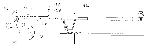
Embodiment of Figures 20-21
Referring now to Figures 20 and 21, an alternate
version of the cover forming and fastening machine is
represented generally by the reference numeral 126a. The
cover former and fastening machine 126a is exactly the same
as the cover forming and fastening machine 126 described above
except that in addition it has a platform extension 188 for
supplying a roll of material 190 which in turn supplies sheets
of material to be used during operation of the apparatus 126a.
The roll of material 190, which is similar to rolls 80 or 90
described in Figures 9-12 above, is mounted upon a support
shaft 192. A portion of the roll 194 is fed through rollers
196 and 198. Roller 196 moves in direction 200 while roller
198 moves in direction 202 thereby causing the portion of
sheet material 194 to be advanced through the rolls 196 and
198 in direction 204 over the platform extension 188.
As described earlier in greater detail in Figure 12,
the portion of material 194 is advanced a predetermined
distance on the upper surface 132 of the platform 130. Once
the portion of material 194 has been advanced a predetermined
distance on the platform a knife 208 is actuated by an
actuator 210 to sever a portion of the material 194 from the
CA 02298148 2000-02-28
roll of material 190 thereby providing a sheet of material
sized for use by the cover forming and fastening apparatus
126a.
~tnbodiments of Figures 22A-22D
5 Referring now to Figures 22A-22D, the cover forming
and fastening apparatus is described fn operation. By
example, the cover forming and fastening machine 126 will be
described in operation in Figures 22A-22D, but it will be
understood by one of ordinary skill in the art that the cover
10 forming and fastening machine 126a works in substantially the
same manner as well as other modified version of the cover
forming and fastening machine 126 described herein.
In operation, a sheet 214 which may be exactly the
same as or similar to any of the sheets described in Figures
15 1-15 may be placed on the upper support surface 132 of the
platform 130 as shown in Figure 22A. A potted plant 215
comprising a plant and the pot in which the plant is disposed
is disposed generally over the sheet of material 214 and above
the opening 152 of the conveyable cover forming assembly or
20 mold 146. The pot of the potted plant has an upper end 216.
The sheet 214 may be supplied to the upper support surface 132
either manually or automatically. The potted plant 215 is
passed in a direction 217 into the interior of the conveyable
cover forming mold 146 thereby forming a covered potted plant
25 218 as shown in Figure 22B. The conveyable cover forming mold
146 containing the covered potted plant 218 is conveyed in a
direction 220 by the drive assembly 164 along the rail 154 to
the fastening machine 170 as shown in Figure 22B. The covered
potted plant 218 in the mold 146 is arrested at a fastening
30 position 180 of the fastening machine 170 as shown in Figure
22C. Once in the fastening position 180 a tie or fastener 222
is disposed about the exterior peripheral surface of the
covered potted plant 218 as shown in Figure 22D.
The tie or fastener 222 may be applied with or
35 without a bow or in any manner feasible by the fastening
machine.
The covered potted plant 218 having the tie or
fastener 222 disposed thereabout is then removed from the
CA 02298148 2000-02-28
31
conveyable cover forming assembly or mold 146 by lifting the
covered potted plant in direction 224. Once the covered
potted plant 218 has been removed from the conveyable cover
forming mold 146, the conveyable cover forming mold 146 is
returned in direction 226 via the rail 154 to the vicinity of
the cover forming platform 132 by the drive assembly 164 as
shown in Figure 22D. . Alternatively, tYte conveyable cover
forming mold 146 may be returned via the rail 154 to the
vicinity of the platform 132 before the covered potted plant
218 has been removed.
In another version of the invention, the cover
forming and fastening machine 126 may further comprise a
labeling apparatus (not shown) for automatically applying a
label to a portion of the outer surface of the cover of the
covered potted plant 218. Such labeling machines are
commercially available and are known to those of ordinary
skill in the art. The sheet of material as described in more
detail above, which is used in accordance with the present
invention, is constructed from material selected from a group
of materials consisting of paper, metal foil, cloth (natural
or synthetic), denim, burlap or polymer film or combinations
thereof.
The apparatus may further comprise a pick and place
assembly (not shown) for picking up the article from an
article supply and far placing the article into the opening
to form the covered article. Additionally, the apparatus may
further comprise a removal assembly for automatically removing
covered article of the platform. The machine 126 may be
located on an axis off a 90° angle and may be portable or
stationary. Such pick and place machines and removal
assemblies are known to those of ordinary skill in the art and
are commercially available.
As noted earlier, the machine can use precut sheets
which are fed manually or automatically with a dispenser which
feeds a sized sheet from a roll to the proper working position
on the platform. Automatic sheet feeding devices are well
known in the art. Examples of such sheet feeding machines are
shown in U.S. patents 4,887,805 issued to Herbert et al.,
4,889,331 issued to Sardella, and 5,090,676 issued to Matsumo
CA 02298148 2000-02-28
32
et al. An automatic sheet feeding machine may be detachably
connected to the framework of the apparatus of the present
invention.
Embodiments of Figures 23-24
5 Shown in Figures 22A-22D is a covered potted plant
218 in which the tie or fastener 222 is applied at a position
below the upper end 216 of the potted plant 215.
Alternatively, as indicated in Figures 23 and 24, a tie or
fastener may be applied at a position above the upper end 216
10 of the potted plant 215. Designated by the general reference
numeral 218a is a covered potted plant in which a tie or
fastener 222a is applied at a position above the upper end 216
of the potted plant 215.
Shown in Figure 24, alternatively, is a covered
15 potted plant 218b in which the potted plant 2I5 is covered by
a sheet of material 228 having a sleeve 230 which forms a
sheet extension and which can be closed at a position 232
above the potted plant 215. The sleeve 230 may be detachable
from the sheet 228 via a perforation zone 234.
20 Changes may be made in the construction and the
operation of the various components, elements and assemblies
described herein or in the steps or in the sequence of steps
of the methods described herein without departing from the
spirit and scope of the invention as defined in the following
25 claims.