Note : Les descriptions sont présentées dans la langue officielle dans laquelle elles ont été soumises.
CA 02299140 2000-02-17
Title: A CENTER PIVOT IRRIGATION SYSTEM
Background of the Invention
1. Field of the Invention
This invention relates to a center pivot irngation syste>xl having the ability
to
irrigate the corners of the field being irngated. More particularly, this
invention relates to
an improved means for controlling the moven~~t of the corner span with respect
to the
center pivot portion of the system.
2. Description of the Related Art
Conventional center pivot irrigation systems comprise an elongated main boom
pivotally connected at its inner end to a center pivot structure and extending
outwardly
therefrom. The main boom of the conventional center pivot irngation system is
comprised
of a plurality of pipes connected together in an end-to-end fashion which are
supported
upon a plurality of drive towers. In most conventional center pivot irrigation
systems, the
outermost drive tower is the master tower with the other drive towers being
selectively
driven in response to angular displacement of the boom section adjacent
thereto.
In the early 1970s, corner systems for center pivot irrigation systems were
developed to enable the corners of a square field to be irngated. See, for
example, U.S.
Patent Nos. 3,797,517; 3,802,726; and 3,902,668. Corner systems usually
consist of an
extension boom or arm, sometimes referred to as a corner span, which is
pivotally
connected to the outer end of the main boom and which is supported on at least
one
steerable drive tower. A guidance system is provided for guiding or steering
the extension
tower, and extension boom, out into the corners of the field as the main arm
travels around
the field. Perhaps the most popular method of guiding the extension tower is
the buried
wire system described in U.S. Patent No. 3,902,668. However, many different
types of
systems for driving the wheels of the extension tower have been previously
provided. See,
for example, U.S. Patent Nos. 4,508,269 and 4,674,681. Further, in assignee's
current
production model, relative movement between the main boom and the extension
boom is
sensed with the drive wheels on the steerable drive tower on the extension
boom being
driven when the main boom has moved forwardly a predetermined distance with
respect to
1
V-98-1 (D3)
CA 02299140 2000-02-17
the extension boom.. When the extension boom "catches up" with the main arm,
the
driving of the drive wheels on the extension tower is discontinued. This
process is
continuously repeated during the movement of the system through the field.
Although the prior art systems do perform generally satisfactorily to drive
the
extension booms, it is believed that the instant invention is more reliable,
more sensitive,
and will require less maintenance than the prior art machines.
Sumit~arv of the Invention w
A center pivot irrigation system with a corner span attachment is described
herein
which includes a center pivot support structure located in the field to be
irngated. An
elongated main water boom, having inner and outer ends, is pivoted at its
inner end to the
center pivot support structure and extends outwardly therefinm. The main water
boom is
comprised of an elongated main water pipe supported upon a plurality of non-
steerable
drive towers which propel the main water pipe around the center pivot support
structure.
An elongated extension boom (corner span, corner boom, corner arm), having
inner and
outer ends, is pivotally connected at its inner end to the outer end of the
main boom with
the extension boom comprising an elongated extension water pipe supported upon
at least
one steerable drive tower. A steering means is provided for steering the drive
wheels on
the steerable drive tower on the corner span as the main boom is moved through
the field.
A drive means is also provided for selectively driving the drive wheels on the
steerable
drive tower. A guidance means is provided for controlling the steering means
whereby the
steerable drive tower is moved along a preselected path, as the main boom
travels over the
field to be irngated, thereby causing the extension boom to be pivotally moved
with
respect to the main boom to cause the extension boom to pivotally extend out
into corner
areas of the field being irrigated and pivotally retract therefrom as the main
boom travels
through the field.
The extension boom water pipe is normally bowed upwardly slightly by means of
a
conventional unde~russ system as are the spans on the main arm. A deflection
sensing
means is positioned on the extension boom water pipe for sensing vertical
deflection of the
extension boom water pipe which is causod by movement of the main boom with
respect to
the extension boom. A control means connects the deflection sensing means and
the drive
2
V-9&1 (D3)
CA 02299140 2000-02-17
means for driving the steerable drive tower upon the deflection sensing means
sensing a
predetermined amount of deflection of the extension water pipe. As the main
boom moves
with respect to the extension boom, the extension boom water pipe tends to be
deflected
vertically downwardly from its normal upwardly bowed position with the drive
wheels on
the steerable drive tower being actuated upon the sensing of a predetermined
amount of
downward deflection of the extension water pipe. Upon actuation of the drive
wheels of
the steerable drive tower on the extension boom, tl~' extension boom m<rves
towards the
main boom and the extension boom water pipe tends to move upwardly to its
normal
upwardly bowed position, at which time the drive wheels on the steerable drive
tower on
the extension boom are deenergized.
It is therefore a principal object of the invention to provide an improved
center
pivot irrigation system having a corner arm system mounted thereon.
Still another object of the invention is to provide an improved method of
controlling the driving of the corner arm extension boom mounted on the outer
end of a
center pivot irrigation system.
Still another object of the invention is to provide a device of the type
described
which eliminates a vast number of the moving parts of conventional corner arm
driving
means, thereby substantially reducing maintenance problems.
Still another object of the invention is to provide a system of the type
described
which is economical of manufacture and durable in use.
These and other objects will be apparent to those skilled in the art.
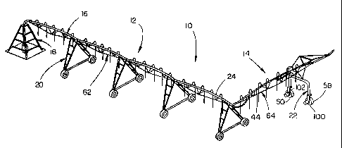
Figure 1 is a perspective view of a center pivot irrigation system having a
corner
span pivotally mounted to the outer end thereof;
Figure 2 is an exploded perspective view of the connection between the main
boom
and extension boom;
Figure 3 is a top elevational view of the connection of Figure 2"~th the
broken
lines illustrating the comer arm water conduit in its completely extended
position;
Figure 4 is a side elevational view of the connation of Figure 2;
3
V-9&1 (D31
CA 02299140 2000-02-17
Figure S is a plan view illustrating the corner arm irrigation system of this
invention;
Figure 6 is a perspective view of the deflection sensing means of this
invention;
Figure 7 is a side view of the deflection sensing means of this invention
illustrating
the extension span in its normally upwardly bowed position;
Figure 8 is a side view similar to Figure 7 except that the extension span has
been
deflected downwardly from the position of Figure 7; --
Figure 9 is a partial bottom perspective view of one end of the deflection
sensing
means;
Figure 10 is an exploded perspective view of the control portion of the
deflection
sensing means; and
Figure 11 is a side elevational view of the control portion of Figure 10.
The numeral 10 refers generally to a self propelled irrigation system which is
comprised of a center pivot irrigation system 12 having a corner arm irngation
system,
corner arm, comer span or extension boom 14 pivotally connected to the outer
end thereof.
Generally speaking, center pivot irrigation system 12 is of conventional
design and
includes a main arm or boom 16 which extends outwardly from a conventional
center pivot
structure 18. Main boom 16 is supported by a plurality of drive towers 20 in
conventional
fashion. The drive towers 20 are designed to propel the center pivot system
around the
center pivot structure 18 in conventional fashion. Corner irrigation system 14
is includes a
steerable drive tower 22.
Referring to Figure 2, the numeral 24 refers to the outermost pipe section of
the
main boom 16. Support 26 is secured to the annular plate 28 mounted at the
outer end of
pipe section 24 and has a hitch ball 30 mounted thereon. Support 26 includes
an arcuate
pipe or elbow section 32 which extends downwardly, outwardly and rearwardly
from the
pipe section 24, as sees in Figure 2. One end of co'~'llbcting hose 34 is
mounted on elbow
32 and is maintained thereon by conventional retainers 36. The other end of
hose 34 has a
flanged pipe 38 securod thereto which is adapted to be socau~ed to the flange
40 which is
mounted on the lower inner end of tubular member 42 which extends downwardly
fmm the
4
V-9&1 (D3)
CA 02299140 2000-02-17
inner end of the water conduit 44 of corner arm 14. The inner end of water
conduit or pipe
44 of extension arm system 14 is provided with an annular flange 46 which is
sealed by
means of plate 48 having beam 50 extending therefrom. The underside of beam SO
is
provided with a ball-shaped pocket 52 which is adapted to receive the hitch
ball 30, as
illustrated in Figure 4. As illustrated in Figure 5, the corner arm 14 trails
the main boom
12 and is moved out into the corner 52 of the field 54 so that the corners of
the field may
be irrigated, as will be described hereinafter.
As stated, the numeral 14 refers to a corner arm system or extension arm
system
including the extension water pipe 44 which is supported by at least one
steerable drive
tower 22 including a pair of steerable drive wheels 58 and 60. The drive
wheels 58 and 60
are steered by any convenient means such as the system disclosed in U.S.
Patent No.
3,902,668 so that the extension boom will be pivotally moved with respect to
the main
boom to cause the extension boom to pivotally extend out into corner areas of
the field and
pivotally retract therefrom as the main boom travels through the field, as
seen in Figure 5.
The electric motors on the drive wheels 58 and 60 may be variable speed or the
"on" and
"off' type, as desired
In most center pivot irrigation systems, the outermost drive tower is the
master
tower with the drive towers inwardly therefrom being slave towers. In other
words, the
outermost master drive tower is driven at the preselected speed or percentage
of time with
the other drive towers being actuated by conventional alignment means so that
the main
boom remains in generally longitudinal alignment.
As the main boom 16 is moved through the field, the drive wheels 58 and 60 on
the
tower 22 must be driven so that the extension boom "keeps up" with the main
boom. In
most prior art corner systems, many moving parts are provided between the
outer end of
the main boom and the inner end of the extension arm. The means for
controlling the
driving of the drive wheels on the corner drive tower also involves several
moving parts
which require c~rrstderable maintenance. In an effort to eliminate the prior
art maintenance
problems of the means for driving the drive tower on the extension boom, the
instant
invention has been provided.
5
V-98-1 (D3)
CA 02299140 2000-02-17
As seen in Figure l, the main boom 12 includes an undertruss system 62 which
bows the water pipes between drive towers 20 upwardly. A suitable undertruss
system 64
is also provided on the extension arm 14 which normally bows the extension
water pipe 44
upwardly to the configuration or shape as seen in Figure 7. A deflection
sensing means 66
is provided on the extension water pipe which senses the vertical deflection
of the
extension water pipe to control the driving of the drive wheels 58 and 60 on
the extension
drive tower 22. c
Deflection sensing means 66 includes an elongated beam 68 which is positioned
beneath extension water pipe 44 in a horizontally disposed position and which
includes an
inner end 70 and an outer end 72. A pair of supports 74 and 76 secure the
inner end of the
beam 68 to the water pipe 44, as seen in the drawings. An externally threaded
rod 78 is
vertically adjustably secured to the outer end 72 of beam 68 and extends
upwardly
therefrom to a control means generally referred to by the reference numeral
80. Control
means 80 includes a pair of vertically disposed support plates 82 and 84
having a plurality
of spacer bolts 86 extending therebetween.
Shaft 88 is rotatably mounted in and extends between plates 82 and 84 and has
cam
90 mounted thereon for rotation therewith. One end of shaft 88 extends through
plate 82
and is connected to a conventional potentiometer 92 whereby rotation of shaft
88 causes
the electrical potential of potentiometer 92 to be either increased or
decreased depending
upon the direction of rotation of shaft 88. Cam 90 has a shaft or stub 94
extending
therefrom which rotatably receives the upper end of a connector 96. The lower
end of
connector 96 threadably receives the upper end of rod 78. The numeral 98
refers to a
safety switch mounted on the inside surface of plate 82 above cam 90 which is
actuated by
cam 90 to deactivate the entire electrical system should the extension boom 14
fail to
maintain its proper operating position with respect to the main boom 12.
Safety switch 98
includes switches 99 and 101 which are engaged and actuated by cam plates 103
and 105
should the comer span 14 fall too-far behind main boom 12 or too far ahead of
main boom
12, respectively, to deactivate the electrical system on the irngation system.
The potentiom~r 92 is suitably electrically connected to the controls for the
drive
motors 100 and 102 for drive wheels 58 and 60, respectively, whereby the
driving of the
6
V-9&1 (D3)
CA 02299140 2000-02-17
drive wheels 58 and 60 are controlled by the deflection sensing means 66, as
will now be
described. As the main boom 16 is propelled around the center pivot structure
18 by the
drive towers 20 in conventional fashion, the extension boom 14 is driven and
steered by the
drive wheels 58 and 60 and follows along behind the main boom 16 and is guided
out into
the corners of the field by the guidance system previously described. As the
main boom 16
moves away from the extension boom 14, the extension water pipe 44 goes into
tension
,r ,and tends to lose its upwardly bowed configuration of :r~~..Figure 7 which
causes contralw=
means 80 to move downwardly with respect to control rod 78, thereby causing
cam 90 to
be rotated in a counterclockwise direction, as viewed from the left in Figure
10, which
results in the potentiometer 92 being actuated which in turn actuates the
drive motors 100
and 102 on drive wheels 58 and 60 to cause the extension boom 16 to be moved
relative to
main boom 12 so that the extension water pipe 56 tends to bow upwardly towards
its
normal position which in turn causes cam 90 to be rotated to rotate
potentiometer 92 in an
opposite direction to that described hereinabove. The upward and downward
bowing or
deflection of the water pipe 56 is constantly repeated to control the driving
of the drive
wheels 58 and 60. As stated, the drive motors 100 and 102 may be of the
variable speed
type or the "on" and "off' type.
The deflection sensing means of the invention eliminates the large number of
moving parts normally associated with corner systems driving controls, thereby
substantially reducing maintenance problems. It is also believed that the
system disclosed
herein is more sensitive and reliable than the prior art systems.
Thus it can be seen that the invention accomplishes at least all of its stated
objectives.
7
V-9&1 (D3)