Note : Les descriptions sont présentées dans la langue officielle dans laquelle elles ont été soumises.
CA 02300072 2000-02-08
WO 99/16222 PCT/SE98I01622
1
I~lET80D AND ARRANGEMENT FOR DEMODULATING DATA SYI~OLS
FIELD OF INVENTION
The present invention relates to a method for demodulating data
symbols having been transmitted through a communication
channel, particularly a channel suffering from one or more
impairments, such as frequency selective fading, inter symbol
interference and distortion, which may be temporally constant
or time-varying.
The invention also relates to an arrangement for carrying out
the method.
DESCRIPTION OF THE PRIOR ART
When digital-data-modulated signals are to be transmitted over a
rapidly fading communication channel, such as a radio channel in
a mobile radio communications system, a commonly used technique
to cope with the changing channel is to include a predetermined
data symbol sequence in the transmitted signal at suitably
frequent intervals. The known symbol sequence is used in a
receiver by a channel equaliser to adapt a demodulator to the
channel's characteristics. This procedure is known as training
or pre-setting the equaliser.
The equaliser typically used models the channel as a linear FIR
filter (FIR = Finite Impulse Response), that is a transversal
filter or a tapped delay line having complex multiplication
weights applied to the tap outputs.
In figure 1 is shown an example of such an equaliser, more
precisely a decision feedback equaliser (DFE), which regurarly
adapts two linear filters 100; 130 to the changing communication
CA 02300072 2000-02-08
WO 99/16222 PCT/SE98/01622
2
channel. The first filter 100 is a prefilter, having a first
transfer function f, which is defined by a first set of filter
coefficients, and the second filter 130 is a feedback filter,
with a second transfer function b, which is defined by a second
set of'filter coefficients. A so called sliver 120 produces hard
data decisions dk and a metric computation unit 140 calculates,
for each hard data decision dk, a corresponding soft value sk. A
summation unit 110 subtracts the feedback filter s 130 output
signal dk*b from the prefilter~s 100 output signal d*h*f+w' and
delivers a difference signal d*h*f+w' - dk*b.
The communication channel is assumed to have an impulse response
h. Received signal samples, representing sent data symbols d,
are here represented by a sampled vector p. Transmission of the
data symbols d, via the communication channel, corresponds to
convoluting the information vector d with the channel's
impulse response h. Moreover, during the transmission noise w
is added. The received signal samples p - d*h+w are
sequentially filtered through the prefilter 100, which is
regularly adapted, so that the communication channel d*h*f+w'
becomes minimum phase, i.e. has its impulse response energy
concentrated as much as possible to the initial part (w' here
represents the noise component w filtered through the prefilter
100, i.e. w' - w*f). The prefilter 100 is also optimised to
remove anti-causal ISI (ISI - Inter Symbol Interference), while
only moderately amplifying the noise contents w in the signal
samples d*h+w. The feedback filter 130 is regularly adapted to
reduce remaining causal ISI between the received data symbols,
i.e. to remove the taps after the main tap of h*f. _The
preffilter 100 is designed so that this main tap h*f also is real
(i.e. includes no imaginary component). For each received burst
CA 02300072 2000-02-08
WO 99/16222 PCT/SE98/01622
3
of signal samples d*h the DFE performs: calculation of
prefilter 100 and feedback filter 130 coefficients; prefiltering
w
f; feedback filtering b; generation of hard data decisions dk
and generation of soft values sk. An estimated burst quality is
in most cases also Weighed in into the soft values sk.
Figures 2a and 2b show per se known methods for respective
forward- and backward-demodulation of received signal samples
in a data burst. The data burst is assumed to comprise a leading
tail Tl of known data symbols, a first set of unknown data
symbols D1, a known training sequence TR, a second set of
unknown data symbols ~Z and a trailing tail T2 of known data
symbols. Either the data burst is demodulated in the forward
direction, whereby primarily F1 the first set of unknown data
symbols D,, is demodulated by using the leading tail Tl and
secondly F2 the second set of unknown data symbols D2 is
demodulated by using the training sequence TR; or the data burst
is demodulated in the backward direction, whereby primarily B1
the second set of unknown data symbols A2 is demodulated by
using the trailing tail T2 and secondly B2 the first set of
unknown data symbols A1 is demodulated by using the training
sequence TR.
If forward-demodulation is selected for a particular data burst,
the unknown data symbo1s.01 received initially and the training
symbols TR received thereafter are demodulated according to the
procedure Fl; F2, as described with reference to figure 2a
above. Nonetheless, before the unknown data symbols D2 received
after the data symbols in the known training sequence TR are
demodulated, the feedback filter 130 is reset and its contents
is replaced with the corresponding symbols, which instead are
read from a memory unit at the receiving party. The analogous
CA 02300072 2000-02-08
WO 99/16222 PCT/SE98/01622
4
is, of course, also true when backward-demodulation Bl; BZ is
selected.
Returning to figure 1, after the prefilter 100 each signal
sample; is subtracted with a feedback filtered version of a
demodulated preceding subset of signal samples, This reduces as
much as possible the influence from previously received samples,
as well as from later received samples. After that, a hard data
decision dk is taken by the slicer 120. The slicer 120 here
simply applies a set of symbol decision boundaries to the real
part of the current signal value at its input. The demodulated
hard data symbol dk is then given by the interval, within which
the real part of the current signal value falls.
The soft values sk are computed in the metric computation unit
140, from prefiltered signal samples d*h*f+w', which are
subtracted with feedback-filtered demodulated hard data symbols
decisions dk*b. Every soft value sk is a vector, whose elements
are probability functions, that for each of the possible symbols
in the symbol alphabet used, reflect the probability of that
symbol being sent. The hard data decision dk, made by the
slicer 120, naturally implies selection of the most probable
symbol sent, which is indicated by the corresponding soft value
sk. For binary symbols it is sufficient for the soft value
vector sk to only contain one single element, whose sign
indicates a corresponding hard data decision dk and whose
modulus reflect the certainty of the hard data decision dk.
Generally, data symbols that are located at a small Euclidean
distance from the demodulated signal are given a higher
probability, than data symbols at larger Euclidean distances.
Furthermore, an estimated burst quality is normally weighed into
r
CA 02300072 2000-02-08
WO 99/16122 PCT/SE98/01622
each soft value sk. An estimated high burst quality gives a
higher a soft value s~ certainty, than a lower estimated burst
quality does.
Furthex detailed descriptions of equalisers in general, and the
5 DFE in particular, can be found in J.G. Proakis "Digital
Communications, 3rd Edition", McGraw-Hill Inc. New York, 1995.
A disclosure of a more efficient demodulator, the so called
Decision-Feedback Sequence Estimator (DFSE) is available in A.
Duel-Hallen & C. Heegard "Delayed Decision-Feedback Sequence
Estimator", IEEE Transactions on Communications, vol. 37, no. 5,
May 1989, pp 428-436.
From US-A-5,400,362 is previously known a method of
communicating digital information, in which subslots of received
signal samples are passed in both a forward and a backward
direction through a demodulator. A subslot quality measure is
calculated for each direction. The direction having the highest
quality is then chosen for decoding the signal samples of the
particular burst.
In the patent document US-A-5,335,250 is disclosed a method for
demodulating data symbols, wherein a set of unknown symbols is
sequentially received between two sets of predetermined symbols.
A certain reference signal is derived from each of the sets of
predetermined symbols. The unknown symbols are forward-
demodulated using the first reference signal and backward-
deuiodulated using the second reference signal. Quality values
for the forward- and backward-demodulation respectively
determine which demodulation order, that is preferable for the
unknown symbols.
US-A-5,155,742 describes a TDM/TDMA digital radio receiver,
which determines whether a received burst should be processed in
CA 02300072 2000-02-08
WO 99/16222 PCT/SE98/01622
6
a time-forward or a time-reversed order. A training sequence
within the burst is circulated multiple times through an
equaliser in the receiver, in both the time-forward and the
time-reversed order. The convergence of a minimum mean-square '
error,' calculated during the circulation, settles the optimal
processing direction for the burst.
In the paper "Combating Pre- and Post-Cursor Channels Using
Forward-Backward State Sequence Detection", International
Conference on Telecommunications, Melbourne, April 1997, pp 1-6
N. C. McGinty et al make known a FBSSD (FBSSD - Feed-Backward
State Sequence Detector), which minimises the effect of ISI on
received digital data. The FBSSD utilises both a forward trellis
and a backward trellis. The forward trellis is used to generate
estimates of transmitted data, that are used in the backward
trellis as estimates of symbols, contained in the pre-cursor
component of a particular burst. The post-cursor component of
the burst is dealt with by a decision feedback algorithm.
SUMMARY OF THE INVENTION
The present invention offers a highly efficient method of .
demodulating a received sequence of data symbols, having been
transmitted through a communication channel, which suffers from
one or more, constant or time-varying impairments, like
frequency selective fading, ISI or distortion. The invention is
primarily intended to be applied in a radio communications
system, however, it may likewise improve the performance of any
network based communication, such as a modem connection.
According to all the methods disclosed in the patent documents w
US-A-5,400,362, US-A-5,335,250 and US-A-5,155,742 received
signal samples are, in one way or another, passed in both the
forward and the backward direction through a demodulator.
T
CA 02300072 2000-02-08
WO 99/16222 PCT/SE98/01622
7
However, none of the documents suggests a combination of the
information derived from the two demodulation directions. On the
contrary, only one particular direction is always selected to be
the direction, through which payload information is extracted
from a'received burst of signal samples.
The above demodulation method taught by N. C. McGinty et al in
"Combating Pre- and Post-Cursor Channels Using Forward-Backward
State Sequence Detection", International Conference on
Telecommunications, Melbourne, April 1997, pp 1-6, implies the
use of a forward trellis as well as a backward trellis, for a
received burst of signal samples. The result from the fozward
trellis is here utilised to reduce pre-cursor ISI in the
backward trellis. However, the paper neither teaches nor
suggests an actual combination of the results from two
independent demodulations of the same signal samples, performed
in opposite directions.
One object of the present invention is thus, to maximally
extract the information contents comprised in a set of
sequentially received signal samples and the correlation between
them, thereby enabling the best possible reproduction at a
receiving party, of the symbol sequence sent out from a
transmitting party, regardless of any qualitative variations on
the channel used to communicate the symbols.
Another object of the invention is to minimise the influence of
error propagation in the demodulation process for a received set
of signal samples.
A further object of the invention is to provide an improved
arrangement for demodulating a received symbol sequence, by use
of a sub-optimal demodulator.
In accordance with the present invention digital-data-modulated
symbols that have been transmitted through a communication
CA 02300072 2000-02-08
WO 99/16222 PCT/SE98/01622
8
channel are demodulated according to the following. First, a
plurality of signal samples, which represent the data symbols,
are sequentially received. Second, the received signal samples
are stored. Third, the stored data samples are demodulated in
either the forward direction or the backward direction. As a
result of this, a first set of soft values is produced, which
for each data symbol expresses a first soft value. Fourth, the
signal samples are demodulated in a direction, which is opposite
to the demodulation direction applied in the third step. This
produces a second set of soft values, which for each data symbol
expresses a second soft value. Fifth is determined, for each
data symbol, a joint soft value from the corresponding first and
second soft values respectively.
The joint soft values may then either be sent to a decoding
means, for decoding of the payload information in the sent data
symbols or directly serve as basis for hard data symbol
decisions.
The method according to invention is characterised by the
features set forth in the characterising clause of claim 1.
According to a preferred embodiment of the invention the soft
values are probability functions that reflect the probability
for each of the symbols in the symbol alphabet used. This
feature is specified in the characterising part of claim 2.
An arrangement according to the invention comprises the
following: means for sequentially receiving a plurality of
signal samples; means for storing the received plurality of
signal samples; means for forward- and backward-demodulating the
stored signal samples, into a first and second set of soft
values respectively and; means for deriving a joint soft value
r
CA 02300072 2000-02-08
WO 99/I6222 PCT/SE98/OI622
9
for each data symbol, from each pair of first and second soft
values.
The arrangement according to the invention is hereby
characterised by the features set forth in the characterising
clause of claim 18.
According to one advantageous embodiment the invention the
arrangement moreover comprises means for storing the respective
first and second sets of soft values for the demodulated data
symbols.
'.0 An arrangement according to this advantageous embodiment of the
invention is hereby characterised by what is apparent from claim
19.
The invention, on average, provides demodulation of a received
data signal at a quality level, that is superior to what may be
accomplished by a corresponding demodulator, which for every
received burst. selects the optimal demodulation direction for
the signal samples contained therein.
According to the present invention, the influence of error
propagation, due to erroneously received signal samples or
erroneously demodulated data symbols, is also minimised.
The demodulated signal quality, which is gained through use of
the invention, can be taken advantage of in various ways. For
instance, given a particular quality level, the complexity of
the demodulator can be lowered. Consequently, without lowering
the standards of quality, cheaper, simpler and/or less power
consuming demodulation devices may be applied any receiver of
digital-data-modulated symbols, such as a radio base station or
a mobile terminal.
CA 02300072 2000-02-08
WO 99/16222 to PCT/SE98/01622
If instead, the~demodulator is fixed, the invention provides a
higher data symbol quality than any of the previously known
solutions does.
The invention moreover offers very flexible digital demodu-
lation solutions, because it is applicable to any kind of
sequentially operating demodulator / equaliser, such as e.g.
LE:s (LE - Linear Equaliser), DFE:s, DFSE:s (DFSE - Decision
Feedback Sequence Estimation) and RSSE:s (RSSE - Reduced State
Sequence Estimation).
BRIEF DESCRIPTION OF THE DRAWINGS
Figure 1 shows a per se known demodulator / equaliser;
Figure 2a illustrates a per se known method of forward-
demodulating a sequence of received signal samples;
Figure 2a illustrates a per se known method of backward-
demodulating a sequence of received signal samples;
Figure 3 shows a flow diagram over the inventive method;
Figure 4 shows a block diagram over an embodiment of the
arrangement according to the invention;
Figure 5 shows a table, comprising intermediate and final
demodulation results of the inventive method, when
applying it the to an example sequence of signal
samples representing multi-bit symbols;
Figure 6 shows a table, comprising intermediate and final
demodulation results of the inventive method, when
applying it the to an example sequence of signal
samples representing binary symbols;
Figure 7 graphically illustrates how soft values for the
individual data bits of a two-bit data symbol are
combined into a joint soft value for the symbol;-in
accordance with the inventive principle;
r i
CA 02300072 2000-02-08
WO 99/16222 PCT/SE98/01622
11
Figure 8 graphically illustrates how error propagation is
suppressed through the inventive method;
Figure 9 shows a diagram over the qualitative performance of
the inventive method, in relation to some pre
y ' viously known demodulation methods;
The invention will now be described in more detail with
,.
reference to preferred exemplifying embodiments thereof and .
also with reference to the accompanying drawings.
DESCRIPTION OF PREFERRED EMBODIMENTS
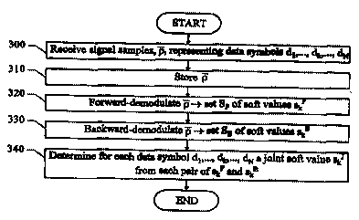
In figure 3 is depicted a flow diagram over the method
according to the invention. Signal samples p, representing
data symbols dl,..., dk,..., dH, which have been received over a
particular communication channel are collected in a first step
300 and stored in a second step 310. Typically but not
necessary, the number of signal samples p is a multiple of the
number of data symbols N, i.e. the number of elements in the
vector p equals x~N, where x is a positive integer. The number
of signal samples p is in any case at least greater than or
equal to the number of data symbols N. In a subsequent step
320, the signal samples p are demodulated in the forward
direction, through a demodulator / equaliser. As a result is
obtained, a first set S~ of soft values skF, which each is
associated with a particular data symbol dk. The soft value skg
is a vector, whose elements are probability functions, that for
each data symbol in the symbol alphabet used, reflect the
probability of that symbol being sent, given the received
signal samples p . If a hard data decision should be requested
at this point (e. g. within a DFE), the decision would be _the
data symbol having the highest probability, according to the
soft value skp. Somewhat simplified, symbol values that are
CA 02300072 2000-02-08
WO 99/16222 PCT/SE98/01622
12
located at a small Euclidean distance from the demodulated
signal are normally given higher probability, than symbol
values at larger Euclidean distances. An estimated burst quality
measure is also commonly weighed into each soft value sk. An
estimated high burst quality gives a soft value sk, which
reflects a higher certainty of the corresponding hard symbol
decision, than a lower estimated burst quality does.
In a next step 330 the very same signal samples p are
demodulated in the backward direction, through a demodulator /
equaliser, which preferably but not necessary, is identical
with the demodulator / equaliser, utilised for the forward-
demodulation. The backward-demodulation results in a second set
SB of soft symbol values skB, which each similarly is associated
with a particular data symbol dk.
The demodulator / equaliser referred to in step 320 and 330 may
be of arbitrary kind, of which the DFE discussed with reference
to figure 1 above constitutes an example. Naturally, it is
irrelevant in which order the forward- and backward-demodulation
is applied, because both steps 320, 330 always are performed
anyway. The order can thus be altered, such that step 330 is
carried out before step 320.
In order to make most possible use of the inforniation contents
in the received signal samples p and the correlation between
them, a joint soft value sk' is determined from each pair of
first and second soft values skF; skB in the following step 340.
The joint soft value skJ, obtained in step 340, may then either
be sent to a decoding means, for decoding the payload
information in the data symbols or directly serve as basis for
hard data decisions dk.
r
CA 02300072 2000-02-08
WO 99/16222 PCT/SE98/01622
13
Figure 4 exemplifies a block diagram over an arrangement for
carrying out the inventive method. A means 400 sequentially
receives signal samples p of a digital-data-modulated signal,
which has been transmitted over a communication channel. The
received signal samples p are stored in a storing means 410,
which preferably is a bi-directional shift register. The signal
samples p are afterwards either shifted out from the first
received signal sample to the last received signal sample or
from the last to the first received signal sample, whereafter
the signal samples p are sent to a demodulator / equaliser
420, of arbitrary sub-optimal kind, such as a LE, DFE, DFSE or
RSSE. The signal samples p will in the former case be
demodulated in the forward direction and in the latter case in
the backward direction. As a result of the forward-demodulation
is obtained, a first set SF of soft values skF, 1 <_ k <_ N. The
first set SF is stored in a storing means 430. The result of
the backward-demodulation is similarly a second set SB of soft
values sk8, 1 <_ k ~ N, which is stored in a storing means 440.
When the two such sets SF; SB have been produced, the soft
values skF; sk$ are sent to a means 450, where for each data
symbol dl - dN a joint soft symbol value skJ is derived from
each pair of first skF and second sk$ soft value respectively.
The joint soft symbol value sk' are collected in a third set SJ
of soft values.
The joint soft values skJ in the third set SJ may then either be
forwarded to a means 460, which determines a resulting set
DR(dl, d2, . . . , dN) of data symbols dl - dN or to a decoder,
which derives payload information, coded into the sent data
symbols dl - dN, directly from the joint soft values skJ-
The arrangement is advantageously comprised in e.g. a radio
base station, a radio base station controller or a mobile radio
CA 02300072 2000-02-08
WO 99/16222 PCT/SE98/01622
14
station, where fast and efficient equalisation of digital-data-
modulated signals is demanded. However, the arrangement is
applicable also in purely network based connections, such as
modem connections.
S
A first example illustrating the inventive concept is shown in a
table of figure 5. Three multi-bit data symbols dl, d2 and d3,
from a particular alphabet [A, B, C, D], are assumed to have
been sent from a transmitting party to a receiving party over a
communication channel, which suffers frnm nnP ~,- m,.r~
impairments. Due to the instability of the communication channel
it is not readily obvious from signal samples at the receiving
party, which symbols dl (A, B, C, D) , dz (A, B, C, D) and d3 (A, B,
C, D), that have been sent.
Received signal samples p are forward-demodulated into a first
set of soft values SF, which each is a vector skF comprising
probabilities PF (dk=A~ p ) , PF (dk=B~ p ) . PF (dk=C~ p ) ; PF (dk=D~ P )
for
the data symbols dl, dz and d3 being the respective symbols A, B,
C; D of the alphabet, given the received signal samples p. In
this example, the symbol value D is estimated to be the most
probable first data symbol dl sent, since the first soft value
s1F indicates that this symbol has the highest probability 0.4.
If a hard data symbol decision dl were to be made on basis of
the first soft value slF, the data symbol D would therefore be
decided. According to the invention however, the signal samples
p are also backward-demodulated into a second set S$ soft
value, which each similarly is a vector sks, that comprises
probabilities PB (dk=A~ p ) , PB (dk=B~ p ) , P$ (dk=C~ p ) ; pe (dk=D~ p )
for
the data symbols dl, d2 and d3 being the respective symbols A, B,
C; D of the alphabet, given the received signal samples p._The
most probable first data symbol dl sent, is now judged to be A,
T
CA 02300072 2000-02-08
WO 99/16222 PCT/SE98101622
since the second soft value s18 indicates that this data symbol
has the highest probability 0.6.
A joint soft value s1J is derived from the first s1F and the
second; s1$ soft values by simply calculating an element-by-
5 element average vector between the first sly and the second s1$
soft values. After performing this, a resulting hard data
decision, d 1R - A, may be taken for the f first data symbol dl .
The symbol value A is selected, because the joint soft value s1J
indicates that this data symbol has the highest combined
10 probability 0.4.
In a corresponding manner, the resulting hard data decisions a2R
A and d3R - B are taken for the second and the third data
symbols d2R and d3R respectively. The first data symbol dl thus
constitutes an example of a "survival-of-the-fittest" hard data
15 decision (i.a. the most probable of two diverging data symbol
estimates is selected), while the second data symbol d2 is an
example of a "unanimous" hard data decision (i.e. a combination
of two agreeing data symbol estimates) and the third data
symbol d3 is an example of a "compromise" hard data decision
(i.e. when a combination of the first skF - A and the second sk8
- C soft values results in a third data symbol B, B ~ A; B ~ C
is estimated to be the most probable data symbol sent).
All the soft values ski, sk$ and skJ may for binary data symbols,
as well as for individual bits of multi-bit symbols, be
expressed via so called log-likelihood functions. The function
sxX = In (P (dk=+1~ p ) /P (dk=-1~ p ) ) . where X = F, B or J is an
example of such a log-likelihood function, for binary data
symbols dk( -+1,-1). The log-likelihood function is so_ a
transformation of the data symbol probability into a logarithmic
representation. When log-likelihood functions are used for
CA 02300072 2000-02-08
WO 99/16222 PCT/SE98/01622
16
obtaining the first skF and the second skB soft values, a joint
soft value skJ is derived by adding the first skF and the second
skB soft values together (which is the logarithm correspondence
to calculating an average value).
An example illustrating this aspect of the inventive concept is
shown in the table of figure 6. On one hand, signal samples
representing a sequence of binary data symbols d~ - dN, from an
alphabet [-1, +1], are assumed to have been demodulated in the
forward direction. This demodulation has resulted in a first set
SF[skF] of soft values skF, 1 < k S N. For reasons of clarity the
_,e
corresponding hard data decisions DF[dkF] are here indicated
alongside the saft values skF. Nevertheless, the hard data
decisions DF[dkF] are, in most cases, unnecessary to take at this
point in the process . If a hard data decisions DF[dkFJ yet were
to be taken, a soft value skF smaller than 0 would be
interpreted as the first hard data symbol -3. in the alphabet,
while a soft symbol value skF greater than 0 would be
interpreted as the second hard data symbol +1 in the alphabet.
On the other hand, the signal samples ire also assumed to have
been demodulated in the backward direction. The result of this
is a second set SB[skB] of soft values s,,B, 1 _< k _< N. The
corresponding hard data decisions D$[dkBJ are for the sake of
consistency indicated here as well.
A joint soft value skJ is then derived from the soft values skF~
skB, for each data symbol dl - dN, by adding together the soft
values skF and skH, that relate to the same data symbol dk.
A soft value above zero thus corresponds to a first hard data
decision dkR - +1 and a soft value below zero corresponds to a
T
CA 02300072 2000-02-08
WO 99/16222 PCT/SE98/01622
17
second hard data decision dkR = -1. A large modulus of a soft
value means that the corresponding demodulated hard data
decision has a relatively high probability of being a correct
estimation of the sent data symbol. A soft value with a small
modulus, on the other hand, indicates a fairly uncertain hard
data decision. To sum up, the sign of the soft value indicates
the binary symbol value and modulus of the soft value reflects
certainty of the corresponding hard data decision.
As can be seen in the table of figure 6, the forward- and
backward-demodulated soft values skF; sk8 for some of the data
symbols d" de and dN_1 have different signs. When the signs of
the soft values skF; skB so differ, the soft value having the
largest modulus (i.e. highest hard data decision certainty)
determines the hard data symbol decision dkR, in a resulting set
D [d R]. Hence, the resulting set of hard data decisions DR[akit,
~k
need not be identical with any of the first DF[dkF] and the
second DB[dk8] sets of hard data decisions. Nevertheless, the
resulting set DR[dk], on average, constitutes a more correct
representation of the transmitted digital information.
If instead multi-bit symbols, like the two-bit symbols A=00,
B=01, C=10; D=11, exemplified in figure 5, are communicated, a
soft value for each specific bit of a symbol can be expressed
via the following log-likelihood functions. The soft value skF
for the first bit B~1, when demodulated in the forward direction
is
P8(dx=C~p7+Pr(dk=D~P)
LLRF (B~1) - 1 pp ~ = A +Pp (dx = B ~ and the corresponding
expression for the second bit B~i is - -
CA 02300072 2000-02-08
WO 99/16222 PCT/SE98/01622
18
'(Pr(dk=Blp)+Pp(dx=Dlp)1 .
LLRF(B#z) - 1 pp(~=AID+Pp(dx=C'~J The soft value sk8 for the
same bits B#1; B#z in the backward direction are
LLR ( B ) _ 1 PB ( dx = C I IP) + Ps ( dx = D I p) and
s #i ~Pa (dx = A +Ps (dx = B
IP I
(Pa(dx=BI~+Pa(dx=DIP)
LLRH (B#z) - 1nI p8 (~ _ A +Pa (dx = C respectively. Consequently
\\
I
all the soft values skF, sk$ and skg can be expressed via the log-
Px(dx=Clp)+Px(dx=DIP)
likelihood functions LLRX (B#1) - l~px (dk = A +Px dx = B and
I~ (
I
Px ( dx = B I p) + Px ( dx = D ( P)
LLRX (B#z) - l~px (dx = A +Px (dk = C ~ where X = F, B or J.
ip m
In figure 7 is depicted a graphical illustration of vectors
representing a first skF, a second skB soft value and a joint
soft value skJ, where the joint soft value skJ is the vector sum
of the first and the second soft values skF; sxB
Further details as to how log-likelihood functions may be
employed to reflect soft values for individual data bits can be
found in J. F-iagenauer et al, "Iterative Decoding of Binary Block
and Convolutional Codes", IEEE Transactinn~ nn Tnfnrmatinn
Theory, vol. 42, no. 2, March 1996, pp 429-445. The document
also teaches generally how soft bit values may be used as a
complement to hard bit decisions, when demodulating received
digital signals.
A graphical illustration of how error propagation is suppressed
by the inventive method is found in figure 8. In all previously
known sub-optimum demodulation methods, there is a risk that
the effects of any erroneously received signal samples or
erroneously demodulated data symbols may propagate to one-or
more adjacent data symbols. If however, there is an error in a
r
CA 02300072 2000-02-08
WO 99/16222 PCT/SE98/01622
19
data symbol in the present invention, such error propagation
will, if it occurs, be distributed in opposite directions from
the erroneous data symbol, during the forward- and backward-
demodulation respectively. The exemplified error in a 10th data,
symbol' dlo, is here assumed to propagate to the three later
received data symbols dll, d~2 and d13, when demodulating in the
forward direction and to the three earlier received data
symbols d~, de and d9, when demodulating in the backward
direction. The combination DR of the soft values SF; SB from the
two demodulation directions, causes the error propagation
effects to cancel each other out. Hence, the influence of error
propagation during demodulation of a received set of signal
samples is reduced significantly through the present invention.
The qualitative performance of the inventive method, in relation
to the previously known demodulation methods, is illustrated in
a diagram of figure 9. Along the vertical axis is represented
the Bit Error Rate BER of a demodulated sequence of digital
symbols, while the carrier-to-interferer level C/I is indicated
in decibel dB along the horizontal axis. A dotted line shows the
performance of a typical uni-directional demodulator / equaliser
(always operating in the forward direction) in respect to these
two parameters, a dashed line shows the corresponding
performance of a demodulator / equaliser, which demodulates
every received burst of signal samples in the optimal direction
for that particular burst and an unbroken line shows the
corresponding performance of a demodulator / equaliser operating
according to the invention. The same DFE is assumed to be
utilised in all three cases.
For very low C/I-levels. the differences in performance between
3p the three demodulating principles are measurable, but -not
considerable. For higher C/I-levels however, the differences
CA 02300072 2000-02-08
WO 99/16222 PCT/SE98/01622
between the principles are more significant. In any case, the
invention always performs better (i.e. gives a lower BER) than
both the uni-directional demodulator / equaliser and the
demodulator / equaliser, that consequently selects the optimal
5 demodulation direction for the received signal samples.
r