Sélection de la langue

Search

Sommaire du brevet 2300605 

Énoncé de désistement de responsabilité concernant l'information provenant de tiers

Une partie des informations de ce site Web a été fournie par des sources externes. Le gouvernement du Canada n'assume aucune responsabilité concernant la précision, l'actualité ou la fiabilité des informations fournies par les sources externes. Les utilisateurs qui désirent employer cette information devraient consulter directement la source des informations. Le contenu fourni par les sources externes n'est pas assujetti aux exigences sur les langues officielles, la protection des renseignements personnels et l'accessibilité.

Disponibilité de l'Abrégé et des Revendications

L'apparition de différences dans le texte et l'image des Revendications et de l'Abrégé dépend du moment auquel le document est publié. Les textes des Revendications et de l'Abrégé sont affichés :

  • lorsque la demande peut être examinée par le public;
  • lorsque le brevet est émis (délivrance).
(12) Demande de brevet: (11) CA 2300605
(54) Titre français: BOITIER ET ENSEMBLE D'ILLUMINATEUR INFRAROUGE
(54) Titre anglais: INFRARED ILLUMINATOR HOUSING AND ASSEMBLY
Statut: Réputée abandonnée et au-delà du délai pour le rétablissement - en attente de la réponse à l’avis de communication rejetée
Données bibliographiques
(51) Classification internationale des brevets (CIB):
  • F21V 33/00 (2006.01)
  • F16M 11/12 (2006.01)
  • G08B 15/00 (2006.01)
  • H04N 7/18 (2006.01)
(72) Inventeurs :
  • FENTON, WILLIAM (Canada)
  • RAAD, ELIE-JEAN (Canada)
(73) Titulaires :
  • SILENT WITNESS ENTERPRISES LTD.
(71) Demandeurs :
  • SILENT WITNESS ENTERPRISES LTD. (Canada)
(74) Agent: NEXUS LAW GROUP LLP
(74) Co-agent:
(45) Délivré:
(22) Date de dépôt: 2000-03-14
(41) Mise à la disponibilité du public: 2001-09-14
Licence disponible: S.O.
Cédé au domaine public: S.O.
(25) Langue des documents déposés: Anglais

Traité de coopération en matière de brevets (PCT): Non

(30) Données de priorité de la demande: S.O.

Abrégés

Désolé, les abrégés concernant le document de brevet no 2300605 sont introuvables.

Revendications

Note : Les revendications sont présentées dans la langue officielle dans laquelle elles ont été soumises.

Désolé, les revendications concernant le document de brevet no 2300605 sont introuvables.
Les textes ne sont pas disponibles pour tous les documents de brevet. L'étendue des dates couvertes est disponible sur la section Actualité de l'information .

Description

Note : Les descriptions sont présentées dans la langue officielle dans laquelle elles ont été soumises.

CA 02300605 2000-03-14
INFRARED ILLUMINATOR HOUSING AND ASSEMBLY
FIELD OF THE INVENTION
The invention herein disclosed relates to the field of security video
monitoring. Specifically the invention is an infrared illuminator housing and
assembly for
illumination of a scene or area for video surveillance monitoring.
BACKGROUND OF THE INVENTION
Video surveillance systems are part of a continually evolving field of
technology wherein many different types of video cameras and infrared
illuminators
have k>een developed. At present most video sur,reillance systems consist of a
video
camera and an infrared (IR) illuminator. The video camera is operative to
receive,
capture, record and store, and optionally transmit, video images of a
particular location
or scene.
The infrared illuminator is operative to generate light in the infrared
spectrum for the illumination of the surveillance area during times of low
ambient light or
contrast, such as during dusk, dawn or night time. The IR illuminator consists
of a
protective housing and a translucent lens which covers the electrical
components
responsible for generating the infrared light. When operative, the infrared
light passes
through the translucent lens to illuminate the scene for higher contrast and
therefore
visibility for the video camera. The electrical components usually contain a
power
1

CA 02300605 2000-03-14
sourcE~, one or more light emitting diodes (LEDs) which generate light in the
infrared
light spectrum, and a sensor for detecting low ambient light levels. The
infrared LEDs
are typically arranged to emit light through the lens to have a particular
angular range,
and travel in a particular direction. The angular range is the range within
which the IR
illuminator will enlighten the scene and it is deternnined by the arrangement
of the LEDs
within the housing.
Such IR illuminators are typically mounted on a wall, ceiling or side of
building to provide illumination for the monitoring of an area or scene of
particular
intere:>t. A common use of such video surveillance camera systems and IR
illuminators
is for outdoor monitoring prisons or other locations where security is of
importance. The
IR illuminators used to light external scenes are often much larger and are
often
manufactured as a floodlight assembly. IR illuminators used to light internal
scenes are
often much smaller and compact, such as those used for passive infrared
intruder
detection.
Since the IR illuminator is often used to illuminate an area of particular
intere:~t, the illuminator is often fixed in its direction according to its
position of
attachment on a wall or ceiling. In particular this direction is determined by
the position
of the illuminator on the mounting surface and thE: direction to which the
lens is facing
and through which the infrared light is then emitted. Often, due to limited
mounting
possibilities and fixed direction of the IR beam, it bs difficult to ensure
illumination of a
2

CA 02300605 2000-03-14
particular segment of the scene. As a result therE~ may be dead zones where
the IR
illuminator cannot be positioned to illuminate. Therefore, a solution to the
aforementioned problem is required. In particular it is highly desirable to
have an IR
illuminator whose IR component can be adjusted independently of the housing.
Infrared motion detection is well known in the art. However, there are few
patents that specifically address the aforementioned problem of providing an
IR
illuminator whose IR component can be adjusted independently of the housing.
U.S.
Patenv: No. 5,886,821 (Sohn) mentions the need to create a small scale motion
detector
with a wide angular range. U.S. Patent No. 5,969,754 (Zeman) uses an IR
illuminator to
enhance the images captured within a video camera. Both patents fails to
address the
problem of providing an IR illuminator with a wide angular range whose IR
component
can bE~ adjusted independently of the housing. U.S. Patent Des. No. 334,541
(Schwartz) provides an ornamental design for a passive infrared detector
mounted in a
housing with a rotational sleeve, however the housing of the device is large
and rather
bulky.
It is the overall object of the present invention to provide an assembly and
housing for an IR illuminator whose IR component can be adjusted independently
of the
housing to provide maximum illumination within a particular scene. It is a
further object
of the present invention to provide a housing comprised of two parts, namely a
base and
a dome-like translucent lens. It is another object of the present invention to
transmit the
3

CA 02300605 2000-03-14
IR light through the entire dome-like translucent I~;ns so that the light is
radiated
outwards in arcs from the plane on which the IR L.EDs lie to provide maximum
illumination of the scene by eliminating dead zonEa. Still another object of
the invention
is to provide an assembly and housing which permits the easy adjustment of the
IR light
emitted via rotation of the dome-like translucent lens around a central axis
attached to
the base.
SUMMARY OF THE INVENTION
In accordance with the broader aspE~cts of the present invention, an
assembly and housing for an infrared (IR) illuminator housing and assembly for
illumination of a scene or area, the assembly and housing being designed to
have a
base and a dome-shaped translucent lens through which IR light is emitted, is
disclo:~ed.
BRIEF= DESCRIPTION OF THE DRAWINGS
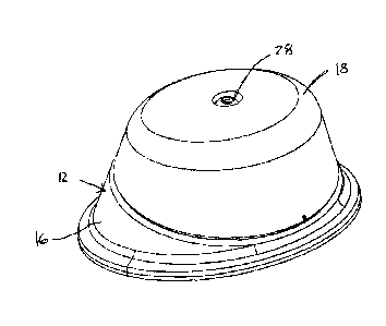
Fig. 1 a depicts a preferred embodiment of the housing of the assembly in
a parallel orientation isomorphic front view of the disclosed invention.
Fig. 1 b depicts the preferred embodiment of the housing of the assembly
in an angled orientation isomorphic front view of the disclosed invention.
4

CA 02300605 2000-03-14
Fig. 2a depicts the preferred embodiment of the housing of the assembly
in a parallel orientation top plan view of the disclosed invention.
Fig. 2b depicts the preferred embodiment of the housing of the assembly
in an angled orientation top plan view of the disclosed invention.
Fig. 3a depicts the preferred embodiment of the housing of the assembly
in a parallel orientation side view of the disclosed invention.
Fig. 3b depicts the preferred embodiment of the housing of the assembly
in an angled orientation side view of the disclosed invention.
Fig. 4a depicts the preferred embodiment of the housing of the assembly
in an isomorphic rear view of the disclosed invention.
Fig. 4b depicts the preferred embodiment of the housing of the assembly
in a beck plan view of the disclosed invention.
Fig. 5a depicts the preferred embodiment of the housing of the assembly
in a cross-section parallel orientation side view of the disclosed invention.
Fig. 5b depicts the preferred embodiment of the housing of the assembly
in a cross-section angled orientation side view of the disclosed invention.
5

CA 02300605 2000-03-14
DETAIILED DESCRIPTION WITH REFERENCE TO THE DRAWINGS
Referring to Figs. 1 a, 1 b, 2a, 2b, 3a, 3b, 4a, 4b, 5a, and 5b, the assembly
comprises a housing assembly 12 and an IR assembly 14. The housing assembly 12
being further comprised of a circular-like base 16 and a dome-like translucent
lens 18,
and the IR assembly 14 being further comprised of a power generation
component, an
IR printed circuit board (PCB) component 20, a cE:ntral axis component 22, and
a light
sensor component. The IR PCB 20 has a donut shape; it is circular and has a
hole in
the middle. The IR LEDs 24 are placed in a specific arrangement on the surface
of the
IR PCB 20, the arrangement being chosen so that the LEDs 24 are placed
symmetrically on the surface of the IR PCB 20. T'he light sensor 26, is a
single non-IR
LED ~nrhich is also placed on the surface of the IR PCB 20. The dome-like
translucent
lens 1B is designed to hold the IR assembly 14, the IR LEDs 24 and non-IR LEDs
26
being placed to face upwards towards the top of the lens 18. The central axis
component consists of a screw 28 and gasket 30, the screw 28 being designed to
attach
the lens 18 to the base 16 by passing through a hole in the middle of the IR
PCB 20.
6

Dessin représentatif
Une figure unique qui représente un dessin illustrant l'invention.
États administratifs

2024-08-01 : Dans le cadre de la transition vers les Brevets de nouvelle génération (BNG), la base de données sur les brevets canadiens (BDBC) contient désormais un Historique d'événement plus détaillé, qui reproduit le Journal des événements de notre nouvelle solution interne.

Veuillez noter que les événements débutant par « Inactive : » se réfèrent à des événements qui ne sont plus utilisés dans notre nouvelle solution interne.

Pour une meilleure compréhension de l'état de la demande ou brevet qui figure sur cette page, la rubrique Mise en garde , et les descriptions de Brevet , Historique d'événement , Taxes périodiques et Historique des paiements devraient être consultées.

Historique d'événement

Description Date
Inactive : Regroupement d'agents 2011-07-06
Inactive : CIB de MCD 2006-03-12
Demande non rétablie avant l'échéance 2002-06-17
Inactive : Morte - Aucune rép. à lettre officielle 2002-06-17
Réputée abandonnée - omission de répondre à un avis sur les taxes pour le maintien en état 2002-03-14
Réputée abandonnée - omission de répondre à un avis exigeant une traduction 2001-11-21
Inactive : Page couverture publiée 2001-09-14
Demande publiée (accessible au public) 2001-09-14
Inactive : Incomplète 2001-08-21
Inactive : Renseign. sur l'état - Complets dès date d'ent. journ. 2001-07-25
Inactive : Abandon. - Aucune rép. à lettre officielle 2001-06-15
Inactive : Lettre officielle 2001-04-24
Inactive : Correspondance - Formalités 2000-06-28
Inactive : Correction selon art.8 Loi demandée 2000-06-28
Inactive : CIB en 1re position 2000-05-26
Inactive : CIB attribuée 2000-05-19
Inactive : Certificat de dépôt - Sans RE (Anglais) 2000-03-30
Exigences de dépôt - jugé conforme 2000-03-30
Demande reçue - nationale ordinaire 2000-03-28

Historique d'abandonnement

Date d'abandonnement Raison Date de rétablissement
2002-03-14
2001-11-21

Historique des taxes

Type de taxes Anniversaire Échéance Date payée
Taxe pour le dépôt - générale 2000-03-14
Titulaires au dossier

Les titulaires actuels et antérieures au dossier sont affichés en ordre alphabétique.

Titulaires actuels au dossier
SILENT WITNESS ENTERPRISES LTD.
Titulaires antérieures au dossier
ELIE-JEAN RAAD
WILLIAM FENTON
Les propriétaires antérieurs qui ne figurent pas dans la liste des « Propriétaires au dossier » apparaîtront dans d'autres documents au dossier.
Documents

Pour visionner les fichiers sélectionnés, entrer le code reCAPTCHA :


Pour visualiser une image, cliquer sur un lien dans la colonne description du document. Pour télécharger l'image (les images), cliquer l'une ou plusieurs cases à cocher dans la première colonne et ensuite cliquer sur le bouton "Télécharger sélection en format PDF (archive Zip)" ou le bouton "Télécharger sélection (en un fichier PDF fusionné)".

Liste des documents de brevet publiés et non publiés sur la BDBC .

Si vous avez des difficultés à accéder au contenu, veuillez communiquer avec le Centre de services à la clientèle au 1-866-997-1936, ou envoyer un courriel au Centre de service à la clientèle de l'OPIC.


Description du
Document 
Date
(aaaa-mm-jj) 
Nombre de pages   Taille de l'image (Ko) 
Dessins 2000-03-14 10 175
Description 2000-03-14 6 197
Page couverture 2001-09-14 1 25
Dessin représentatif 2001-08-30 1 8
Certificat de dépôt (anglais) 2000-03-30 1 163
Demande de preuve ou de transfert manquant 2001-03-15 1 108
Courtoisie - Lettre d'abandon (lettre du bureau) 2001-07-23 1 171
Rappel de taxe de maintien due 2001-11-15 1 112
Courtoisie - Lettre d'abandon (incompléte) 2001-12-12 1 171
Courtoisie - Lettre d'abandon (taxe de maintien en état) 2002-04-11 1 182
Correspondance 2000-03-30 1 14
Correspondance 2000-06-28 3 107
Correspondance 2001-04-19 1 10
Correspondance 2001-08-14 1 20