Sélection de la langue

Search

Sommaire du brevet 2301425 

Énoncé de désistement de responsabilité concernant l'information provenant de tiers

Une partie des informations de ce site Web a été fournie par des sources externes. Le gouvernement du Canada n'assume aucune responsabilité concernant la précision, l'actualité ou la fiabilité des informations fournies par les sources externes. Les utilisateurs qui désirent employer cette information devraient consulter directement la source des informations. Le contenu fourni par les sources externes n'est pas assujetti aux exigences sur les langues officielles, la protection des renseignements personnels et l'accessibilité.

Disponibilité de l'Abrégé et des Revendications

L'apparition de différences dans le texte et l'image des Revendications et de l'Abrégé dépend du moment auquel le document est publié. Les textes des Revendications et de l'Abrégé sont affichés :

  • lorsque la demande peut être examinée par le public;
  • lorsque le brevet est émis (délivrance).
(12) Brevet: (11) CA 2301425
(54) Titre français: TOUR D'ENTRAINEMENT A CHENILLE POUR SYSTEME D'IRRIGATION AUTOMOTEUR
(54) Titre anglais: A TRACKED DRIVE TOWER FOR A SELF-PROPELLED IRRIGATION SYSTEM
Statut: Périmé et au-delà du délai pour l’annulation
Données bibliographiques
Abrégés

Abrégé anglais


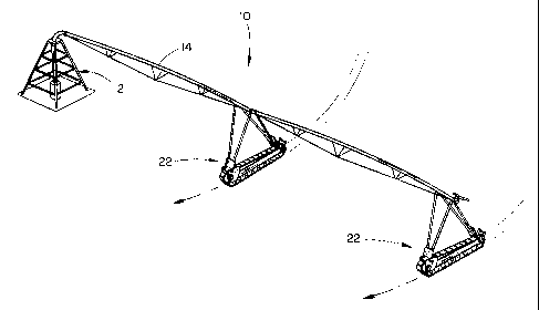
A drive tower for a self-propelled irrigation system is described which is of
the
track type. The drive tower includes an elongated frame having opposite ends.
A drive
pulley is mounted at one end of the frame while a tail pulley is mounted at
the other end of
the frame. The drive pulley comprises a pair of spaced-apart, disc-shaped
plates having
spaced-apart rods secured thereto and extending therebetween at the periphery
thereof for
engagement with the interior surface of the belt. The interior surface of the
traction belt is
provided with a plurality of longitudinally spaced-apart lugs which are
received between
the rods on the drive wheel. The tail pulley and the idler pulleys have
peripheries which
receive the lugs on the inner surface of the belt. The exterior surface of the
belt is also
provided with a plurality of transversely extending traction lugs. The belt is
driven by
means of a double reduction gear drive.

Revendications

Note : Les revendications sont présentées dans la langue officielle dans laquelle elles ont été soumises.


I claim:
1. A drive tower for a self-propelled irrigation system, comprising:
an elongated, generally horizontally disposed frame having opposite
ends;
a first drive pulley rotatably mounted, about a horizontal axis, at one
end of said frame;
a drive motor for rotatably driving said first drive pulley;
a second pulley rotatably mounted, about a horizontal axis, at the other
end of said frame;
a plurality of idler assemblies secured to said frame, between said
ends of said frame between said first drive pulley and said second pulley;
an endless traction belt extending around said first drive pulley, said
second pulley, and said idler assemblies;
said traction belt having inner and outer surfaces;
said inner surface of said traction belt having a plurality of
longitudinally spaced-apart lugs extending therefrom along the center line
thereof;
said first drive pulley comprising a pair of vertically disposed,
horizontally spaced-apart plate members;
the distance between said plate members being less than the width of
said traction belt;
a plurality of spaced-spark rods secured to and extending between said
plate members at the periphery thereof and extending outwardly from said plate
members for engagement with the interior surface of said traction belt;
7

said rods being sufficiently spaced-apart to permit at least one of said
lugs of said traction belt to be received therebetween;
and an irrigation pipe support means extending upwardly from said
frame for supporting an irrigation pipe thereon.
2. The drive tower of Claim 1 wherein said traction belt has a
plurality of spaced-apart traction lugs provided on the outer surface thereof,
said
lugs being disposed transversely with respect to the direction of movement of
said
traction belt.
3. The drive tower of Claim 1 or 2 wherein a belt tensioning means
is associated with said second pulley.
4. The drive tower of any one of Claims 1 to 3 wherein said second
pulley has an annular recess formed in the periphery thereof for receiving
said lugs
therein.
5. The drive tower of any one of Claims 1 to 3 wherein said second
pulley comprises a pair of horizontally spaced-apart pulley wheel members
having a
central space therebetween for receiving said lugs therein.
6. The drive tower of any one of Claims 1 to 5 wherein said frame
comprises a steel, tube.
7. The drive tower of Claim 6 wherein said steel tube has a
rectangular cross section.
8. The drive tower of any one of Claims 1 to 7 wherein said idler
assemblies are of the walking beam type.
8

9. The drive tower of any one of Caims 1 to 8 wherein said idler
assemblies are positioned beneath said frame.
10. The drive tower of any one of Claims 1 to 3 wherein said drive
motor comprises a double reduction gear drive motor.
11. A drive tower for a self-propelled irrigation system, comprising:
a frame having opposite ends;
a first drive pulley rotatably mounted, about a horizontal axis, at one
end of said frame;
a drive motor for rotatably driving said first drive pulley;
a second pulley rotatably mounted, about a horizontal axis, at the other
end of said frame means;
a plurality of idler assemblies secured to said frame between said first
drive pulley and said second pulley;
an endless traction belt extending around said first drive pulley, said
second pulley, and said idler assemblies;
said traction belt having inner and outer surfaces;
said inner surface of said traction belt having a plurality of
longitudinally spaced-apart lugs extending therefrom along the center line
thereof;
said first drive pulley comprising a pair of vertically disposed,
horizontally spaced-apart disc-shaped plate members;
track engagers mounted on said plate members for engaging the
inside surface of said traction belt;
9

and irrigation pipe support means extending upwardly from said frame
for supporting an irrigation pipe thereon.
12. The drive tower of Claim 11 wherein said traction belt has a
plurality of spaced-apart traction lugs provided on the outer surface thereof,
said
lugs being disposed transversely with respect to the direction of movement of
said
traction belt.
13. The drive tower of Claim 11 or 12 wherein belt tensioning
means is associated with said second pulley.
14. The drive tower of any one of Claims 11 to 13 wherein said
second pulley has an annular recess formed in the periphery thereof for
receiving
said lugs therein.
15. The drive tower of any one of Claims 11 to 13 wherein said
second pulley comprises a pair of horizontally spaced-apart pulley wheel
members
having a central space therebetween for receiving said lugs.
16. The drive tower of any one of Claims 11 to 15 wherein said
frame comprises a steel tube.
17. The drive tower of Claim 16 wherein said steel tube has a
rectangular cross section.
18. The drive tower of any one of Claims 11 to 17 wherein said idler
assemblies are of the walking beam type.
19. The drive tower of any one of Claims 11 to 18 wherein said idler
assemblies are positioned beneath said frame.
10

20. The drive tower of any one of Claims 11 to 19 wherein said
drive motor comprises a double reduction gear drive motor.
11

Description

Note : Les descriptions sont présentées dans la langue officielle dans laquelle elles ont été soumises.


CA 02301425 2000-03-16
TITLE: A TRACKED DRIVE TOWER FOR A
SELF-PROPELLED IRRIGATION SYSTEM
Background of the Invention
1. Field of the Invention
This invention relates to a drive tower for a self propelled irngation system
such as
a center pivot or linear move irngation system and more particularly to a
tracked drive
tower for those irngation systems.
2. Description of the Related Art
Self propelled irngation systems such as center pivot and linear move systems
normally employ a plurality of wheeled drive towers which support and propel
the
irngation pipe over the area to be irrigated. The wheels of the drive towers
frequently
create deep wheel tracks in the field. Further, in some situations, the drive
wheels slip and
are unable to propel the irngation system. In an attempt to solve the problems
associated
with wheeled drive towers, there have been some attempts at providing a drive
tower
wherein the same is propelled by an endless track much like a tank track or
crawler tractor
type. One such system is disclosed in U.S. Patent No. 5,078,326. Other tracked-
type
systems for drive towers for irrigation systems are found in certain of the
prior art cited
during the prosecution of the above-identified patent.
Although tracked drive towers have been previously provided, it is believed
that the
tracked drive towers of the prior art suffer from certain disadvantages. It is
believed that
certain of the prior art devices suffer slippage between the drive wheels or
track pulleys
and the endless track. Further, it is believed that certain of the tracked
drive towers of the
prior art are overly complicated. Still another disadvantage of the prior art
systems is that
the belts wear readily due to the means of driving the same.
Summal-xof the Invention
A drive tower for a self propelled irrigation system is disclosed wherein an
endless
track is utilized rather than a pair of pneumatic drive wheels. The tracked
drive tower of
this invention comprises an elongated tubular frame. A first drive pulley is
rotatably
1
(V-98-11 )

CA 02301425 2006-05-12
mounted, about a horizontal axis, at one end of the tubular frame. A double
reduction gear drive is operatively connected to the first drive pulley for
rotatably
driving the first drive pulley. A second pulley is rotatably mounted, about a
horizontal axis, at the other end of the tubular frame. A plurality of idler
pulleys
mounted on walking beams are secured to and positioned beneath the tubular
frame
between the first drive pulley and the second pulley. An endless traction belt
extends around the first drive pulley, the second pulley and the idler pulleys
whereby
rotation of the first drive pulley by the gear drive will cause the traction
belt to propel
the drive tower and move the irrigation pipe over the area to be irrigated.
The inner
surface of the traction belt has a plurality of longitudinally spaced-apart
lugs
protruding therefrom along the centerline thereof, The traction belt also has
a
plurality of spaced-apart traction lugs provided on the outer surface thereof
with
those lugs being disposed transversely with respect to the direction of
movement of
the traCtian belt. The first drive pulley comprises a pair of vertically
disposed,
horizontally spaced-apart disc-shaped plate members having a central axle
extending therethrough. The distance between the disc-shaped plate members is
less than the width of the traction belt. A plurality of spaced-apart rods are
secured
to and extend befinreen the plate member's at the periphery thereof and extend
transversely outwardly from the plate members far engagement with the interior
2p surface of the traction belt. The rods are sufficiently spaced-apart to
permit the lugs
of the traction belt to be received therebetween. An irrigation pipe support
structure
extends upwardly form the frame far supporting the irrigation pipe thereon.

CA 02301425 2006-05-12
It is therefore a principal object of the invention to provide a tracked drive
tower for a self-propelled irrigation system.
Brief Description of the Drawinos
Figure 1 is a perspective view of a center pivot irrigation system having the
tracked drive towers of this invention.
Figure 2 is an end view of a prior art drive tower.
Figure 3 is an end view of the tracked drive tower of this invention.
Figure 4 is a partial side elevational view of one end of the tracked drive
tower
of this invention.
Figure 5 is a partial side elevational view of the other end of the tracked
drive
tower.
Figure fi is a side elevational view of the tracked drive tower.
Figure 7 is a partial perspective view of one end of the drive tower of this
invention.
Figure 8 is an end etevational view of the drive tower of this invention with
the
endless track removed therefrom.
Figure 9 is a sectional view seen on lines 9-S of Figure 6 with the endless
belt
removed.
Figure 9 o is an end elevational view of the tail pulley.
~0 Descriation of the Preferred Embodiment
l'he numeral 10 refers generally to a center pivot irrigation system including
a
Center pivot structure 12 and a main water conduit 14 extending outwardly
therefrom. Figure 2 illustrates a conventional drive tower of the prior art
which
3

CA 02301425 2006-05-12
inoludes a pair of drive wheels 6 driven by a motor 18 in canventianal
fashion. As
seen in Figure 2, the drive wheels 16 create wheel tracks ar ruts referred to
generally by reference numeral 20.
3A

CA 02301425 2000-03-16
Although Figure 1 illustrates that the irngation system has two drive towers,
it should be
understood that any number of drive towers could be employed. Further, it
should be
noted that sprinklers are provided on the main water conduit 14 in
conventional fashion.
Figure 1 illustrates the drive tower of this invention which is referred to
generally by the
reference numeral 22. Drive tower 22 includes a tubular frame referred to
generally by the
reference numeral 24. Frame 24 is preferably comprised of a 4" x 10" tube
constructed
from 7 gage steel. Plates 32 and 34 are secured to one end of frame 24 and
have a top plate
or cover 36 secured thereto and extending therebetween. Tower braces 38 and 40
are
secured to plates 32 and 34 and extend upwardly to plate 42 to which they are
bolted or
otherwise secured. Tower arms 44 and 46 are secured to plate 42 and extend
upwardly
therefrom to support the irngation pipe in conventional fashion.
A plurality of idler wheel assemblies 48 are secured to and are positioned
below
frame 24 for engagement with the interior surface of the endless track 50. As
best seen in
Figures 6 and 9, each of the idler wheel assemblies 48 includes a pair of
horizontally
spaced-apart idler wheels 52 and 54 which define a recessed portion 56
therebetween
adapted to receive the lugs 58 which protrude from the inner surface of the
endless belt SO
in a longitudinally spaced-apart manner along the centerline of the belt 50.
It is preferred that the idler wheel assemblies 48 be of the walking beam
type. As
seen in Figure 6, a generally horizontally disposed beam 60 is pivotally
mounted on
bracket 61, which is secured to frame 24 by welding or the like, by means of
shaft 62.
Pairs of idler wheels are rotatably mounted on opposite ends of frame 24. The
walking
beam construction of the idler wheel assemblies 48 enables the idler wheels to
be
constructed from a low cost plastic material. If plastic idler wheels were
rigidly mounted,
they would possibly fail as the tower crossed rigid objects, such as rocks or
the like.
The numeral 64 refers to a drive pulley which is mounted on axle 66 which is
rotatably mounted on the plates 32 and 34, as best seen in Figure 8. A double
reduction
gear motor 65 is connected to axle 66 to drive the same. Drive pulley 64 is
comprised of a
pair of vertically disposed, horizontally spaced-apart disc-shaped plates 72
and 74 which
are mounted on the axle 66 for rotation therewith and which have a plurality
of spaced-
apart rods 76 mounted in the peripheries thereof which protrude transversely
outwardly
4
w-ss-~ ~

CA 02301425 2000-03-16
from the plates 72 and 74 for engagement with the inside surface of the track
or belt 50.
The rods 76 are spaced-apart a sufficient distance to enable at least one of
the lugs 58 to be
received therebetween. Rotation of the drive pulley 64 causes the rods 76 to
engage the
lugs 58 to positively apply driving force to the endless belt 50. A belt
tensioning apparatus
is provided on the other end of the frame means and is referred to generally
by the
reference numeral 78. Belt tensioning apparatus 78 includes a pair of arms 80
and 82
which are secured at their lower ends to the side frame members 26 and 28.
Axle 84 is
longitudinally received by elongated slots formed in the arms 80 and 82. As
seen in Figure
5, the slot formed in arm 80 is referred to generally by the reference numeral
86. The
numeral 88 refers generally to a pulley which is mounted on axle 84 for
rotation therewith
and which is sometimes referred to as a tail pulley. Pulley 88 is comprised of
a pair of
pulley wheel members 90 and 92 which are spaced-apart, as illustrated in
Figure 10, to
define a recess 94 therebetween adapted to receive the lugs 58 therein. Pulley
88 may be
raised or lowered on the arms 80 and 82 to either tighten or loosen the
tension in the belt
50. Braces extend upwardly from side frame members 26 and 28, as seen in
Figure 5, and
are referred to generally by the reference numeral 96. Braces 96 are connected
to the
irngation pipe to support the same in conventional fashion.
Belt 50 is preferably constructed of a suitable plastic or rubber material and
has the
lugs 58 extending on the inside surface thereof as previously described.
Additionally, the
exterior surface of belt 50 is provided with a plurality of transversely
extending traction
lugs 98.
Actuation of the gear motor 65 causes the drive pulley 64 to rotate so that
the rods
76 engage the lugs 58 to positively propel the belt 50. Not only do the rods
76 provide
engagement surfaces for the lugs 58, but the outer ends thereof serve to
support the belt
without undue wear thereof. The interaction between the rods 76 and the lugs
58 ensures
that there will not be any slippage between the drive pulley and the belt.
The tracked drive tower of this invention is very stable in use and will not
create
deep wheel tracks or ruts unless unusual circumstances arise. The track 50
engages the
ground over a wide area and ensures that there will be sufficient traction
between the belt
and the ground to propel the drive tower over the area to be irrigated.
5
(V-98-11)

CA 02301425 2000-03-16
The steel beam or frame 24 adds the sufficient strength to the assembly which
is
required as the towers move through the field.
Thus it can be seen that the invention accomplishes at least all of its stated
objectives.
6
w-ss-~ ~ ~

Dessin représentatif
Une figure unique qui représente un dessin illustrant l'invention.
États administratifs

2024-08-01 : Dans le cadre de la transition vers les Brevets de nouvelle génération (BNG), la base de données sur les brevets canadiens (BDBC) contient désormais un Historique d'événement plus détaillé, qui reproduit le Journal des événements de notre nouvelle solution interne.

Veuillez noter que les événements débutant par « Inactive : » se réfèrent à des événements qui ne sont plus utilisés dans notre nouvelle solution interne.

Pour une meilleure compréhension de l'état de la demande ou brevet qui figure sur cette page, la rubrique Mise en garde , et les descriptions de Brevet , Historique d'événement , Taxes périodiques et Historique des paiements devraient être consultées.

Historique d'événement

Description Date
Le délai pour l'annulation est expiré 2008-03-17
Lettre envoyée 2007-03-16
Accordé par délivrance 2006-09-19
Inactive : Page couverture publiée 2006-09-18
Inactive : Taxe finale reçue 2006-07-06
Préoctroi 2006-07-06
Un avis d'acceptation est envoyé 2006-06-22
Lettre envoyée 2006-06-22
Un avis d'acceptation est envoyé 2006-06-22
Inactive : Approuvée aux fins d'acceptation (AFA) 2006-06-12
Modification reçue - modification volontaire 2006-05-12
Inactive : Dem. de l'examinateur par.30(2) Règles 2006-04-26
Exigences relatives à la révocation de la nomination d'un agent - jugée conforme 2005-10-12
Exigences relatives à la nomination d'un agent - jugée conforme 2005-10-12
Inactive : Lettre officielle 2005-10-12
Demande visant la révocation de la nomination d'un agent 2005-10-03
Demande visant la nomination d'un agent 2005-10-03
Lettre envoyée 2005-01-24
Toutes les exigences pour l'examen - jugée conforme 2005-01-13
Exigences pour une requête d'examen - jugée conforme 2005-01-13
Requête d'examen reçue 2005-01-13
Inactive : Page couverture publiée 2001-09-16
Demande publiée (accessible au public) 2001-09-16
Lettre envoyée 2000-05-17
Inactive : CIB en 1re position 2000-05-10
Inactive : Transfert individuel 2000-04-12
Inactive : Lettre de courtoisie - Preuve 2000-04-11
Inactive : Certificat de dépôt - Sans RE (Anglais) 2000-04-06
Demande reçue - nationale ordinaire 2000-04-06

Historique d'abandonnement

Il n'y a pas d'historique d'abandonnement

Taxes périodiques

Le dernier paiement a été reçu le 2006-02-02

Avis : Si le paiement en totalité n'a pas été reçu au plus tard à la date indiquée, une taxe supplémentaire peut être imposée, soit une des taxes suivantes :

  • taxe de rétablissement ;
  • taxe pour paiement en souffrance ; ou
  • taxe additionnelle pour le renversement d'une péremption réputée.

Les taxes sur les brevets sont ajustées au 1er janvier de chaque année. Les montants ci-dessus sont les montants actuels s'ils sont reçus au plus tard le 31 décembre de l'année en cours.
Veuillez vous référer à la page web des taxes sur les brevets de l'OPIC pour voir tous les montants actuels des taxes.

Historique des taxes

Type de taxes Anniversaire Échéance Date payée
Taxe pour le dépôt - générale 2000-03-16
Enregistrement d'un document 2000-04-12
TM (demande, 2e anniv.) - générale 02 2002-03-18 2002-03-04
TM (demande, 3e anniv.) - générale 03 2003-03-17 2003-02-27
TM (demande, 4e anniv.) - générale 04 2004-03-16 2003-12-22
Requête d'examen - générale 2005-01-13
TM (demande, 5e anniv.) - générale 05 2005-03-16 2005-02-11
TM (demande, 6e anniv.) - générale 06 2006-03-16 2006-02-02
Taxe finale - générale 2006-07-06
Titulaires au dossier

Les titulaires actuels et antérieures au dossier sont affichés en ordre alphabétique.

Titulaires actuels au dossier
VALMONT INDUSTRIES, INC.
Titulaires antérieures au dossier
JOHN A. CHAPMAN
Les propriétaires antérieurs qui ne figurent pas dans la liste des « Propriétaires au dossier » apparaîtront dans d'autres documents au dossier.
Documents

Pour visionner les fichiers sélectionnés, entrer le code reCAPTCHA :


Pour visualiser une image, cliquer sur un lien dans la colonne description du document. Pour télécharger l'image (les images), cliquer l'une ou plusieurs cases à cocher dans la première colonne et ensuite cliquer sur le bouton "Télécharger sélection en format PDF (archive Zip)" ou le bouton "Télécharger sélection (en un fichier PDF fusionné)".

Liste des documents de brevet publiés et non publiés sur la BDBC .

Si vous avez des difficultés à accéder au contenu, veuillez communiquer avec le Centre de services à la clientèle au 1-866-997-1936, ou envoyer un courriel au Centre de service à la clientèle de l'OPIC.


Description du
Document 
Date
(aaaa-mm-jj) 
Nombre de pages   Taille de l'image (Ko) 
Dessin représentatif 2001-09-04 1 11
Abrégé 2000-03-15 1 23
Description 2000-03-15 6 263
Revendications 2000-03-15 3 114
Dessins 2000-03-15 5 160
Description 2006-05-11 7 248
Revendications 2006-05-11 5 127
Dessin représentatif 2006-08-17 1 11
Courtoisie - Certificat d'enregistrement (document(s) connexe(s)) 2000-05-16 1 113
Certificat de dépôt (anglais) 2000-04-05 1 163
Rappel de taxe de maintien due 2001-11-18 1 112
Rappel - requête d'examen 2004-11-16 1 116
Accusé de réception de la requête d'examen 2005-01-23 1 176
Avis du commissaire - Demande jugée acceptable 2006-06-21 1 162
Avis concernant la taxe de maintien 2007-04-29 1 172
Correspondance 2000-04-05 1 15
Taxes 2003-02-26 1 32
Taxes 2003-12-21 1 32
Taxes 2002-03-03 1 31
Taxes 2005-02-10 1 26
Correspondance 2005-10-02 3 93
Correspondance 2005-10-11 1 14
Correspondance 2005-10-11 1 17
Correspondance 2006-07-05 2 49