Note : Les descriptions sont présentées dans la langue officielle dans laquelle elles ont été soumises.
CA 02302083 2010-12-03
APPARATUS FOR COATING A PIPE SURFACE
The present invention relates generally to the field of apparatus for
coating an inside surface of a pipe.
BACKGROUND OF THE INVENTION
Pipes are often used to carry fluids or abrasive slurries as part of a
treatment or disposal process. As the fluid passes through the pipe,
frictional forces
against the pipe walls can cause the pipe walls to wear. The effect of these
frictional
forces is magnified on the curved portions of the pipe as a result of complex
flow
patterns and the forces from the fluid impacting the pipe surface caused by
the fluid
changing direction. Abrasives suspended within the fluid (e.g. solids commonly
associated with mining slurries or sludge) can be even more detrimental to the
pipe
walls. Whatever the cause, these forces cause the pipe walls to wear even
faster,
eventually causing the pipe walls to crack or burst where the walls have worn
thin.
To minimize the effects of these frictional forces on the pipe walls, a
protective coating is applied (e.g., welded or sprayed) to the inner surface
of the
pipe. To provide effective protection against wear on the pipe wall, it is
important
that the entire area is com pletely coated with the coating material. Areas
left
unprotected will continue to be vulnerable to fracture.
An example of the prior art in this field is disclosed in US Patent No.
4,513,443 (Kostecki). Kostecki discloses an apparatus for coating an internal
wall of
a curved pipe with a layer of protective material. The apparatus has a guide
means,
a longitudinally flexible member, means for mounting a coating means for
incremental rotation by the longitudinally flexible member, a drive means to
drive the
CA 02302083 2010-12-03
2
longitudinally flexible member relative to the curved pipe, and a means to
automatically step the flexible member and consequently rotate the coating
means.
However, a disadvantage of using the flexible member in Kostecki is the
associated
inaccuracy in translating the rotational steps along the longitudinally
flexible
member. Because the coating means cannot be accurately rotated, the protective
material can be misapplied resulting in either gaps or overlap between the
applied
strips of protective material.
SUMMARY OF THE INVENTION
A primary object of the present invention is to provide an apparatus to
io coat an internal surface or wall of a pipe with a layer of protective
coating.
According to a first aspect of the invention there is provided apparatus
for coating an interior surface of a pipe, said apparatus comprising:
an elongate support member arranged to be mounted so as to extend
along the interior of the pipe at a position at or parallel to a longitudinal
axis of the
pipe;
a coating carriage mounted on the elongate support member for
movement along the elongate support member;
a carriage drive system for driving the coating carriage longitudinally
along said elongate support member to a position where the coating carriage
enters
into the pipe for passage at least partly through the pipe along an area of
the pipe to
be coated-
a coating device for coating the interior surface of the pipe from a
supply of a coating material;
CA 02302083 2010-12-03
3
the coating device being carried on the coating carriage such that the
coating device moves along the area of the pipe to be coated with the coating
carriage;
the elongate support member and the coating carriage having
cooperating elements which maintain the coating carriage at a fixed rotational
orientation relative to the elongate support member; and
a coating device drive system including at least one drive motor carried
by the coating carriage for moving the coating device angularly relative to
the
coating carriage.
According to a second aspect of the invention there is provided an
apparatus for coating an interior surface of a pipe, said apparatus
comprising:
an elongate support member arranged to be mounted so as to extend
along the interior of the pipe at a position at or parallel to a longitudinal
axis of the
pipe; }
a coating carriage mounted on the elongate support member for
}
movement along the elongate support member;
a carriage drive system for driving the coating carriage longitudinally
along said elongate support member to a position where the coating carriage
enters
into the pipe for passage at least partly through the pipe along an area of
the pipe to
be coated;
a coating device for coating the interior surface of the pipe from a
supply of a coating material;
CA 02302083 2010-12-03
4
the coating device being carried on the coating carriage such that the
coating device moves along the area of the pipe to be coated with the coating
carriage;
the elongate support member and the coating carriage having
s cooperating elements which maintain the coating carriage at a fixed
rotational
orientation relative to the support elongate support member; and
a coating device drive system including at least one drive motor carried
by the coating carriage for moving the coating device angularly relative to
the
coating carriage;
to at least one intermediate carriage mounted on said elongate support
member for movement therealong;
and a plurality of link arms for transferring motion from the carriage
drive system to the coating carriage through said at least one intermediate
carriage
including a first link arm from the drive carriage to said at least one
intermediate
15 carriage and a second link arm from said at least one intermediate carriage
to the
coating carriage.
According to a third aspect of the invention there is provided a method
for coating an interior surface of a pipe, said method comprising:
mounting an elongat e support member so as to extend along the
20 interior of the pipe at a position at or parallel to a longitudinal axis of
the pipe;
mounting a coating carriage on the elongate support member for
movement along the elongate support member;
CA 02302083 2010-12-03
S
driving the coating carriage longitudinally along said elongate support
member by a carriage drive system to a position where the coating carriage
enters
into the pipe for passage at least partly through the pipe along an area of
the pipe to
be coated;
coating the interior surface of the pipe by a coating device from a
supply of a coating material;
carrying the coating device being on the coating carriage such that the
coating device moves with the coating carriage along the area of the pipe to
be
coated;
the elongate support member and the coating carriage having
cooperating elements which maintain the coating carriage at a fixed rotational
orientation relative to the elongate support member; and
providing a coating device drive system including at least one coating
drive motor carried by the coating carriage for moving the coating device
angularly
relative to the coating carriage.
The invention also includes a pipe when coated by the method as
defined above.
Thus the preferred arrangement disclosed in more detail hereinafter
provides an apparatus for coating an interior surface of a pipe. The apparatus
has a
center rod defining the elongate support member with a substantially square-
cross
section that extends axially along the centerline of the pipe. A coating
carriage
slidably engages the substantially square cross section of the center rod,
which
ensures that the coating carriage maintains a fixed rotational orientation
relative to
CA 02302083 2010-12-03
6
the center rod. An index motor is provided on the coating carriage to elevate
a
coating device to coat the Interior surface of the pipe. Th e coating device
is
rotationally attached to the coating carriage and the index motor has an
adjustable
index position. Thus, as the index motor is indexed by a fixed angular
Increment,
the coating device is rotated to a rotational position that corresponds to the
index
position of the index motor. A separate drive motor is carried by a drive
carriage and
propels the drive carriage longitudinally along the center rod. Generally, at
least one
intermediate carriage that slidably engages the substantially square cross
section of
the center rod translates motion of the drive carriage to the coating carriage
so that
the coating carriage, and hence the coating device moves longitudinally along
the
center rod within the interior of the pipe. By positioning the index motor
near the
coating device and providing a center rod that moves the coating carriage
longitudinally while maintaining a fixed rotational profile, the rotational
position of the
coating device can be accurately controlled so that the entire interior
surface of the
coating device is coated without overlap or gaps in the coating.
These and other advantages, features, and objects of the present
invention will be more readily understood in view of the following detailed
description
and the drawings.
BRIEF DESCRIPTION OF THE DRAWINGS
The present Invention can be more readily understood in conjunction
with the accompanying drawings, in which:
CA 02302083 2010-12-03
Figure 1 is a top plan view of an apparatus showing the type of
machine with which the present invention is concerned and showing the pipe in
cross section.
Figure 2 is a side cross sectional view taken along lines 2-2 of Figure
1.
Figure 3 is a cross-sectional view along the lines 3-3 of Figure 1.
Figure 4 is an isometric view of an intermediate carriage of the
apparatus of Figure 1.
Figure 5 is front elevational view of the intermediate carriage of the
1o apparatus of Figure 4.
Figure 6 is an isometric view of the welding torch and wire feed of
Figure 1.
DETAILED DESCRIPTION
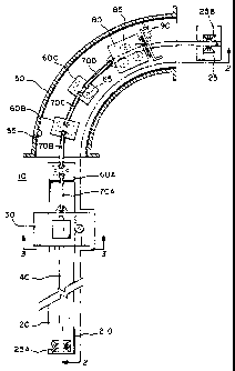
An apparatus 10 of the present invention is shown In Figures 1 and 2.
1s A frame 20 supports a drive carriage 30 and a center rod 40. The center rod
40
extends along the length of the frame 20 and beyond the frame 20 above the
floor 5
so that the center rod 40 can be extended through a pipe 50 along its
centerline. In
Figure 1, three intermediate carriages 60A-C and an coating carriage 80 are
shown
slidably engaging the center rod 40. The center rod 40 is shaped to provide
support
20 for the intermediate carriages 60A-C and the coating carriage 80 so that
each
carriage travels longitudinally along the center rod 40 in a fixed orientation
relative to
the center rod 40. For example, the center rod 40 can have a square cross
section
as shown in Figure 5. The intermediate carriages 60A-C are connected to one
CA 02302083 2010-12-03
8
another between the drive carriage 30 and the coating carriage 80 with link
arms
70A-D. A coating device 90 (e.g., a weld head, sprayer, nozzle, etc., or even
a
cleaning device such as a brush) is rotationally attached to the coating
carriage 80.
Thus, when the drive carriage 30 is driven the length of the frame 20, as
described
in more detail below, the intermediate carriages 60A-C, and consequently the
coating carriage 80, slide along the center rod 40 axially through the pipe
50. As the
coating carriage 80 is moved along the center rod 40, the coating device 90
applies
a strip of protective coating to the inner wall 55 of the pipe 50. As shown in
Figure 2,
at the end of each longitudinal pass, an index motor 200 mounted to the
coating
io carriage 80 is then activated to rotate the coating device 90, as described
in more
detail below, and another strip of protective coating is applied to the inner
wall 55 of
the pipe 50 as the intermediate carriages 60A-C and the coating carriage 80
are
moved along the center rod 40 by the drive carriage 30.
Details of the Frame and Center Rod Support.
1s The frame 20 (shown in Figures 1 and 2) supports the drive carriage
30 and the center rod 40. In the preferred embodiment, the frame 20 is a solid
steel
structure. However, any suitable frame 20 can be used under the teachings of
the
present invention, including a beam (e.g. a steel I-Beam), an A-frame assembly
or
any other solid or framed support assembly. Likewise, any suitable material
(e.g.,
20 metal alloys, plastic composites, wood, a combination thereof, etc.) may be
used so
long as it provides the requisite strength to support the drive carriage 30
and the
center rod 40.
CA 02302083 2010-12-03
9
The frame 20 is fitted with a rack gear 210. The rack gear 210 is
preferably a rack gear mounted on at least one side or the top of the frame
20. The
drive carriage 30 carries a drive motor 320. A pinio n gear 330 is
rotationally
mounted to the drive motor 320 and engages the rack gear 210 of the frame 20.
Thus, as the drive motor 320 is operated and the pinion gear 330 engages the
rack
gear 210 of the frame 20, the drive carriage 30 travels over the center rod 40
along
the length of the frame 20. Although the rack gear 210 is preferably a gear to
receive the teeth of the pinion gear 330, any suitable rack gear 210 could be
used
that allows the drive motor 320 to propel the drive carriage 30 along the
length of the
to frame 20. For example, a rubber strip could be used as long as enough
friction
could be generated so that a complimentary pinion gear 330 (e.g., with a
rubber
engaging surface) would engage the rack gear 210 and move the drive carriage
30
along the length of the frame 20 without slipping.
As shown in Figure 2, a guide portion 220 can also be mounted to the
is frame 20. For example, the guide portion 220 can be a triangular railing
formed on
opposing sides of the frame 20, as shown in Figure 3. The drive carriage 30
has a
pair of guide wheels 350 rotationally attached on each side of the drive
carriage 30.
These guide wheels 350 are formed to compliment (e.g., inversely formed) the
guide
portion 220 of the frame 20 and thus slidably support the drive carriage 30
above the
20 center rod 40. When the drive motor 320 propels the drive carriage 30 along
the
length of the frame 20, the drive carriage 30 is guided along the frame 20 by
the
guide wheels 350 engaging the guide portion 220.
CA 02302083 2010-12-03
The frame 20 is preferably straight and the rack gear 210 extends for a
length at least equal to the length of the pipe 50 that is to be coated. Thus
the entire
length of the pipe 50 that is to be coated can be coated when the drive
carriage 30
travels the length of the rack gear 210. This arrangement allows the pipe 50
to
5 remain stationary and instead the coating device 90 is moved through the
pipe 50.
However, it is to be expressly understood that the length and shape of the
frame 20
can be shorter or longer depending on factors such as available space, average
length when multiple pipes 50 are to be coated, expense, etc. In other
embodiments, the pipe 50 will need to be moved after each section Is coated to
coat
io additional lengths of the pipe 50. Likewise, collapsible portions of the
frame 20,
extensions, etc. can be used to provide adjustable lengths of the frame 20.
The center rod 40 is preferably securely fastened above the frame 20
to a support bracket 25A mounted on the frame 20. The center rod 40 can also
be
fastened using a second support bracket 25B mounted above the floor 5 on a
center
rod support 23. However, for short distances, or if the center rod 40 is
sufficiently
rigid to support the weight of the intermediate carriages 60 and the coating
carriage
80, the second support bracket 25B and center rod support 23 can be omitted
altogether. Although the center rod 40 shown in Figures 1 and 2 extends the
length
of the frame 20 so that the drive carriage 30 travels over the center rod 40.
In
another embodiment, the center rod 40 can be mounted at the end of the frame
20
closest to the pipe 50.
In the preferred embodiment, the center rod 40 has a substantially
square cross section. However, the center rod 40 can be rectangular, square
with
CA 02302083 2010-12-03
11
rounded corners, diamond-shaped, etc. It is only important that the
intermediate
carriages 60 and the coating carriage 80 do not rotate relative to the center
rod 40
(i.e., the carriages 60, 80 have a fixed rotational orientation relative to
the center rod
40). Therefore, in other embodiments, the center rod 40 can be triangular,
elliptical
or even circular with a notch. For example, in an embodiment where the center
rod
40 is circular with a notch, the intermediate carriages 60 and the coating
carriage 80
would be fitted with a complimentary key to prevent rotation about the center
rod 40.
The frame 20 has been described as having a distinct rack gear 210
and guide portion 220, which are separate and distinct from the center rod 40.
In this manner, the frame 20 supports the drive carriage 30, and the
center rod 40 only provides support for the intermediate carriages 60 and the
coating
carriage 80. However it is to be expressly understood that these components
need
not be separate and distinct from one another, and that only their function
and
interaction with one another is important under the teachings of the present
invention. For example, the rack gear 210 and guide portion 220 can be made
separately from the frame 20 and attached thereto, or formed as part of the
frame
20. The rack gear 210 can be formed to serve both the function of the rack
gear 210
and the guide portion 220. Likewise, the rack gear 210 and the guide portion
220
need not be part of the frame 20, and can instead be integrated separately or
in
combination as part of the center rod 40. In another embodiment, the center
rod 40
and the frame 20 (with its rack gear 210 and guide portion 220) can be
combined to
perform the same function as each component performs independently.
Details of the Drive Carriage.
CA 02302083 2010-12-03
12
An embodiment of the drive carriage 30 is shown in more detail in
Figure 3. The drive carriage 30 supports a drive motor 320 connected to a
pinion
gear 330, a wire feed 340, and guide wheels 350. The drive motor 320 is
fixedly
attached to the drive carriage 30. A drive shaft 325 extends from the drive
motor
320 to the drive or pinion gear 330 that engages the rack gear 210 of the
frame 20.
The drive carriage 30 is supported above the frame 20 preferably by opposing
pairs
of guide wheels 350 that serve to stabilize and guide the drive carriage 30
along the
frame 20. The guide wheels 350 need not be provided in opposing pairs so long
as
the guide wheels 350 support the drive carriage 30 above the frame 20. For
to instance, a single guide wheel opposing one or more guide wheels can be
used
under the teachings of the present invention.
Optionally, center rod wheels 360 that engage the center rod 40 can
also be used as an additional guide or In lieu of the guide wheels 350 and the
guide
portion 220. Thus, when the drive motor 320 is driven, the drive axle or shaft
325
rotates the pinion gear 330 which engages the rack gear 210 of the frame 20.
The
guide wheels 350 roll along the guide portion 220, moving the drive carriage
30
along the length of the frame 20.
As illustrated in Figure 3, the wire feed 340 carries feed lines 250 that
are required to operate the coating device 90. The feed lines 250 will vary
depending on the use of the apparatus 10. For instance, when the apparatus 10
Is
used to coat the inside of pipe 50 with a welded layer of protective coating,
the feed
lines 250 can be electric wires, gas (e.g., butane, propane, etc.) lines, flux
cable, etc.
Likewise, if the apparatus 10 is used to clean the pipe 50, feed lines 250 can
be
CA 02302083 2010-12-03
13
hoses that supply water and cleaning solution to the coating device 90.
Whatever
the feed lines 250 are used with apparatus 10, the wire feed 340 serves to
hold the
feed lines 250 so that they do not interfere with the drive mechanism (i.e.,
pinion
gear 330 and rack gear 210). Tubing 500 (e.g., such as is shown in Figure 5)
can
also be used to carry multiple feed lines 250.
The drive carriage 30 is configured as a box, as shown in Figure 3, to
house the drive motor 320. However, in other embodiments, the drive carriage
30
can be a simple platform, frame structure, etc. In yet another embodiment, the
drive
carriage 30 can be configured with, for example, bearings and bearing races
instead
1o of the guide wheels 350 and the center rod wheels 360. The specific
configuration
of the drive carriage 30 is not important to the present invention. It is only
important
that the drive carriage 30 provide a mounting for the drive motor 320 so that
the
drive motor 320 can propel the drive carriage 30 along the length of the rack
gear
210 of the frame 20.
Details of the Intermediate Carriages
An embodiment of the intermediate carriage 60 is shown in more detail
in Figures 4 and 5. In Figure 4, intermediate carriage 60 is configured as a
plate that
supports two opposing carriage wheels 65 rotationally mounted thereon. Each
carriage wheel 65 is formed to roll along the center rod 40. Thus, in the
preferred
embodiment, when the center rod 40 Is square, each carriage wheel 65 has a
flat
surface that rolls against the flat surface of the center rod 40, thus
engaging the
center rod 40 and guiding the intermediate carriage 60 longitudinally along
the
center rod 40 so that the intermediate carriage 60 maintains a fixed
rotational
CA 02302083 2010-12-03
14
orientation with respect to the center rod 40. In another embodiment in which
the
center rod 40 is, for example, diamond shaped, the carriage wheels 65 would be
accordingly made so as to compliment the center rod 40. As such, the carriage
wheels 65 stabilize the intermediate carriage 60 so that it maintains a fixed
rotational
orientation with respect to the center rod 40. That is, the intermediate
carriage 60
does not rotate with respect to the center rod 40 and thus slides parallel and
longitudinally to the center rod 40. Any number of carriage wheels 65 can be
used
under the teachings of the present invention. In other embodiments, the
carriage
wheels 65 may take any suitable form, such as bearings, rollers, etc., or even
be a
to guide that slides within a slot formed on the center rod 40. The
configuration of the
carriage wheels 65 need only permit the intermediate carriage 60 to freely
slide
along the center rod 40 while maintaining a fixed rotational profile.
The intermediate carriage 60 is linked between the drive carriage 30
and the coating carriage 80 by means of link arms 70. When more than one
intermediate carriage 60 Is used with the apparatus 10, each intermediate
carriage
60 is similarly linked to one another using additional link arms 70 (e.g.,
link arms
70A-D shown in Figure 1). The link arms 70 are pivotally connected to the
intermediate carriage 60, the drive carriage 30, and the coating carriage 80
using
any suitable pivotal connection pin 410 (e.g., a bolt, a cotter pin assembly,
etc.). In
this manner the intermediate carriages 60 and the coating carriage 80 travel
along
the curved portion of the center rod 40 (e.g., as shown in Figure 1), much
like the
cars of a freight or passenger train make turns along a curved portion of
railroad
track. The link arms 70 can be made longer or shorter depending on the degree
of
CA 02302083 2010-12-03
curvature in the center rod 40. In addition, while in the preferred
embodiment, only a
single link arm 70 is used between each carriage 30, 60, 80, multiple link
arms 70
may be used between each or some carriages 30, 60, 80 for additional support.
Likewise, similar design considerations will dictate the length of link arms
70, which
5 can be uniform or vary in size. In other embodiments, link arms 70 can be
omitted
altogether, and the intermediate carriages linked directly to one another. It
is only
important that the intermediate carriages provide sufficient flexibility
between the
drive carriage 30 and the coating carriage 80 so that the coating carriage 80
can be
moved along the curved portions of the center rod 40.
to A support arm 420 for carrying feed lines 250 from the wire feed 340
on the drive carriage 30 to the coating device 90 on the coating carriage 80
is also
shown in Figures 4 and 5. Preferably, the support arm 420 has a semi-circular
portion 425 on which the feed lines 250 are supported. Other suitable support
arms
420 can be used under the teachings of the present Invention, such as support
arms
is 420 having a loop, a cylinder, a V-shaped support, a clamp, etc. It is only
important
that the support arm 420 retain the feed lines 250 so that the feed lines 250
do not
become entangled and interfere with operation of the carriages 30, 60, 80.
Any number of intermediate carriages 60 can be used under the
teachings of the present invention. In the preferred embodiment, the number of
intermediate carriages 60 that are used will depend on a variety of factors
including
the length of the pipe 50 that is to be coated, the degree of curvature of the
pipe 50,
the support required for the feed lines 250, etc. For example, a very short
length of
straight pipe 50 will require fewer intermediate carriages 60 and in some
CA 02302083 2010-12-03
16
embodiments, intermediate carriages 60 may not be needed at all. In other
embodiments, such as when the apparatus 10 is used to coat a long stretch of
pipe
50 having a severe curvature, a greater number of intermediate carriages 60
are
required than when a short or relatively straight pipe 50 is used. Likewise,
heavy
feed lines 250 will require more intermediate carriages 60 to support the feed
lines
250 above the center rod 40, whereas stiff or lightweight feed lines 250 will
require
fewer Intermediate carriages 60. Other design parameters will dictate the
number of
Intermediate carriages and the present invention is not to be limited by the
number
of intermediate carriages 60.
io Details of the Coating carriage.
An embodiment of the coating carriage 80 is shown in more detail in
Figure 6. The coating carriage 80 preferably supports three index wheels 85A-
C.
Each index wheel 85 is rotationally attached to the coating carriage 80, for
example
using any suitable wheel axle. The index wheels 85 are formed similarly to the
carriage wheels 65, described above, in that each index wheel 85 rolls along
the
center rod 40 so that the coating carriage 80 travels parallel and
longitudinally to the
center rod 40 without rotating relative to the center rod 40 (i.e.,
maintaining a fixed
rotational profile relative to the center rod 40). The preferred embodiment as
shown
in Figure 6 has two index wheels 85A, B triangularly opposing a third index
wheal
85C. This configuration supports the coating carriage 80 while permitting the
coating carriage 80 to readily travel along the curved portions of the center
rod 40.
However, other suitable configurations (e.g., those discussed for intermediate
carriage 60) are applicable to the index wheels 85. A feed support arm 420 can
also
CA 02302083 2010-12-03
17
be mounted to the coating carriage 80 to guide the feed lines 250 to the
coating
device 90.
The coating carriage 80 also supports the Index motor 200 which turns
the Index drive sprocket 640. The index drive sprocket 640 rotates the Index
gear
620 to which an Index arm 600 Is securely fastened. The coating device 90 is
securely attached to the index arm 600 (e.g., with suitable angle irons 605).
Thus,
when the index motor 200 is driven, the index drive sprocket 640 rotates the
index
gear 620 and rotates the Index arm 600 to rotate the coating device 90. The
index
motor 200 is preferably a conventional stepper motor that can be stepped a
io predetermined angular increment so that the coating device 90 is rotated
(e.g., in the
direction of arrow 650) and stopped at the desired angular position.
The coating carriage 80 is shown in Figure 6 configured as a housing
that surrounds the index wheels 85, the index motor 200, and travels about the
center rod 40. However, the coating carriage 80 can be configured as a
platform
similar to the intermediate carriages 60, or a framed support structure that
fits over
the center rod 40, etc.
The preferred embodiment has thus been described with the apparatus
10 of the present invention including a drive carriage 30 to carry the drive
motor 320,
a coating carriage 80 to carry the coating device 90, and intermediate
carriages 60
Interconnected with link arms 70 to translate motion from the drive carriage
30 to the
coating carriage 80. However, it is to be expressly understood that the drive
motor
320 can be carried by the coating carriage 80 itself, in which case, the drive
carriage
and intermediate carriages 60 would not be needed. In such an embodiment the
CA 02302083 2010-12-03
18
center rod 40 is modified so that the drive motor 320 is able to directly
propel the
coating carriage 80 along the center rod 40.
Operation.
In operation, each of the above described components of the
apparatus 10 preferably interact in the following manner, as shown in Figures
2 and
6. Typically, the drive carriage 30 will alternately move between a fully
retracted
position and a fully extended position. That is, when the drive carriage is in
the fully
retracted position, the drive carriage 30 is positioned near the support
bracket 25A.
When the drive carriage 30 is in the fully extended position, the drive
carriage 30 is
1o at the end of the frame 20 nearest the pipe 50. These positions are used
merely for
convenience in the following description, and in use, the drive carriage 30
can be
positioned anywhere along the frame 20.
When the drive carriage 30 is in the fully retracted position, the coating
carriage 80, and hence the coating device 90 are positioned at the first end
720 of
the pipe 50. The drive motor 320 is then driven so that the drive carriage 30
travels
along the frame 20, as described above. As the drive carriage 30 travels
(e.g., in the
direction of arrow 740 in Figure 2) along the frame 20, the drive carriage 30
pushes
the intermediate carriages 60A-C (i.e., pushes link members 70A-D and
consequently intermediate carriages 60A-C), which in turn push the coating
carriage
80 along the center rod 40 toward the second end 730 of the pipe 50 (e.g. in
the
direction of arrow 745 in Figure 2). As the coating carriage 80 is pushed
along the
center rod 40, the coating device is operated to apply a layer of protective
coating
longitudinally along a strip of the wall of the pipe 50. When the drive
carriage 30
CA 02302083 2010-12-03
19
reaches the end of the frame 20 nearest the pipe 50 (i.e., the fully extended
position)
the drive carriage 30 is stopped, and the index motor 200 is stepped (e.g., in
the
direction of arrow 650) to rotate the coating device 90 so that the protective
coating
being applied by the coating device 90 Is now being applied In a strip above
or
below and immediately adjacent to the strip of protective coating applied in
the
previous pass. The drive motor 320 is then reversed so that the drive carriage
30
now travels from the fully extended position back toward the fully retracted
position.
As the drive carriage 30 travels toward the fully retracted position, the
drive carriage
30 pulls each intermediate carriage 60A-C (i.e., by pulling link members 70A-
D) and
io the coating carriage 80. As a result, the coating device 90 is again moved
along the
length of the pipe 50 so that a second layer immediately adjacent (or slightly
overlapping) the first layer of protective coating is applied to the pipe wall
55. In this
manner, the pipe wall 55 is accurately coated so that no part of the pipe wall
55 is
left unprotected and any overlap between the strips of protective coating is
the result
of desired overlap instead of an attempt to correct for error in the
rotational position
of conventional coating apparatus.