Note : Les descriptions sont présentées dans la langue officielle dans laquelle elles ont été soumises.
CA 02302274 2000-02-29
1
SPECIFICATION
CIRCUIT ARRANGEMENT AND METHOD FOR MINIMIZING BIT ERRORS
Digital data that, for example, are transmitted via optical fibers or
coaxial cables are converted back into digital data in the receiver by
sampling the received signal. At a specific sampling time, a threshold
decision respectively decides whether a high or low voltage potential value
is allocated to the received signal in a sampling interval.
Given known receiver units, it is standard that the sampling time at
1 o the height of the threshold for the threshold decision are determined and
set
upon initialization of the receiver unit. Due to changing system properties,
however, the required values for an optimum sampling time and the optimum
threshold change. Given such values set once for initialization of the
receiver unit, a degeneration is kept slight on the basis of a decision
process
when the changing system properties of the receiver unit are co-involved in
the determination of the sampling time as well as of the threshold.
Given receiver units for ultra-high rate optical transmission systems
wherein it is not possible to adequately prescribe the system reserves in
such a way, a monitoring path for setting the sampling time and/or the
2 o threshold is utilized in addition to a signal path. In a receiver unit
given this
transmission system, a first decision unit is integrated in the signal path
and
a second decision unit is integrated in the monitor path. The inputs of the
first and second decision unit are charged with the same, received signals.
The second decision unit in the monitor path serve, by variation such as, for
2s example, an artificial deterioration of the threshold and of the sampling
time,
to respectively determine an optimum value for these without the quality of
the transmitted signal in the signal path being negatively influenced.
Whenever an improvement compared to the signal path has been identified,
the first decision unit in the signal path takes the optimized values for the
3 o sampling time and the threshold.
CA 02302274 2000-02-29
Substitute Page
In another method for controlling the threshold and given the pre-
condition that the plurality of zeroes and ones of the transmitted digital
signal
sequence are usually equally distributed, in a criterion for an optimized
threshold control is derived by average formation in transmission paths that
are
highly affected by errors. This method, however, involves the disadvantage
that
it cannot be applied given optical transmission paths having a bit error rate
on
an order of magnitude of 10-'°.
European Patent Application EP 0 455 910 A2 discloses a threshold
control.
The invention is based on the object of specifying a circuit arrangement
as well as a method for minimizing bit errors in the regeneration of a digital
signal sequence.
This object is achieved by the features of patent claims 1 and 7.
The invention yields the advantage that no additional optical reception
components are required for regeneration of received, digital signal
sequences.
The invention yields the further advantage that no artificial deterioration
of the bit error rate must be induced in order to find out the direction in
which,
for example, the sampling time must be varied.
Further characteristics are recited in the subclaims.
2 0 Further characteristics of the invention can be seen from the following,
more detailed explanation of an exemplary embodiment with reference to
drawings.
Shown are:
Figure 1 an eye pattern;
Figure 2 a block circuit diagram of a control arrangement;
Figure 3 an illustration of individual bit sequences that yield the eye
pattern when combined;
Figure 4 a classification of possible decision unit conditions in conjunction
with an eye pattern; and
3 0 Figure 5 a table that reproduces the functioning of an error analysis
unit.
Figure 1 shows an eye pattern. Temporal signal curves of a received bit
sequence N-1, N, N+1 as shown in Figure 3 are illustrated in the eye pattern.
As a rule, an eye-pattern as shown in Figure 1 derives given an
superimposition
of the received bit sequences N-1, N, N+1. A decision unit
CA 02302274 2000-02-29
3
status EZ derives from the intersection between a voltage potential value
SW for a threshold decision unit and a sampling time AP. The respectively
optimum voltage potential value SW for the threshold decision unit and the
sampling time AP yields a minimum bit error rate in the regeneration of a
received digital signal. As a rule, the position of the decision unit status
EZ
is to be anticipated close to the center of the eye pattern. In optical
systems
that work with many optical fiber amplifiers, the voltage potential SW,
however, can also lie close to the zero potential level.
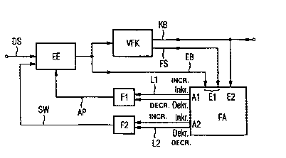
Figure 2 shows a block circuit diagram of a control arrangement for
1o setting the sampling time AP and the voltage potential value SW for a
decision unit. This control arrangement is essentially composed of a
decision unit EE, of a forward error correction unit VFK, of an error analysis
unit FA and of a first and second control filter F1, F2.
An incoming digital signal sequence DS is applied to an input of the
decision unit EE. An output of the decision unit EE is connected to an input
of the forward error correction unit VFK and to a first input E1 of the error
analysis unit FA. A first output of the forward error correction unit VFK is
connected to the first input E1. An error signal FS that contains an
information about a deviation of the bit sequence EB from a corrected bit
2 o sequence KB is adjacent at a second output of the forward error unit VFK.
The second output of the forward error correction unit VFK is connected to
a second input E2 of the error analysis unit FA.
A first output A1 of the error analysis unit FA has a first line pair L1
connected to an input of the first control filter F1. A second output A2 of
the
error rate analysis unit FA is connected to an input of the second control
filter F2 with a second line pair L2. The first and second control filter F1,
F2
is respectively fashioned as a control filter with a time-weighted averaging.
The outputs of the first and second control filter F1, F2 are connected to
inputs of the decision unit EE. The first input E1 of the error analysis unit
FA
3 o is charged with the bit sequence EB or with the error signal FS output by
the
forward error correction VFK, and a second input E2 of the error analysis
unit FA is charged with the corrected bit sequence KB.
CA 02302274 2000-02-29
4
An optimized sampling time AP for a sampling unit is defined with the
first control filter F1; an optimized value SW for a threshold decision unit
is
defined with the second control filter F2. A sampling decision unit and a
threshold decision unit are arranged in the decision unit EE. Given this
control arrangement, the control criterion is the bit error rate that is to be
minimized. In order to derive a control criterion for the sampling time AP and
the threshold SW that describe a decision unit status EZ, the bit sequence
EB that is received and still affected by errors is subjected to a forward
error
correction in the forward error correction unit VFK.
to In addition to containing the actual information, the bit sequence EB
also contains parity bits. An error localization is possible by interpretation
of the information bits together with the parity bits. This forward error
correction VFK is dimensioned such that the residual error probability of the
corrected bit sequence KB is negligible.
The corrected bit sequence KB is optionally compared in the error
analysis unit FA to the received bit sequence EB or to the error signal FS.
Output quantities of the error analysis unit FA are respective increment
commands and de-increment commands that respectively lower or increase
the value for the threshold SW and the sampling time AP. The modification
2 0 of the threshold SW and of the sample AP is respectively collected and
weighted in the control filters F1, F2 over a longer time span. The control
filters F1, F2 respectively see to it that it is not random, individual events
but
only those events with a certain frequency of occurrence that have an
influence on the decision unit status EZ.
The corrected bit sequence KB and the bit sequence EB are
compared to one another bit-by-bit in the error analysis unit FA.
Alternatively, thereto, the error signal FS that is adjacent at the first
input E1
of the error analysis unit FA together with the corrected bit sequence KB can
also be employed for the correction of the threshold SW and of the sampling
3 o time AP.
In the correction of the sampling time AP and of the voltage potential
value for the threshold SW, the preceding and the following bit of the
~
CA 02302274 2000-02-29
corrected bit sequence KB or of the bit sequence EB are taken into
consideration.
A delayed processing of the successor bit without causality problems
can be made available by intermediate storage that is required because of
5 the forward error correction in the forward error correction unit VFK. For
analysis of the digital data, the bit N to be interpreted in the bit sequence
EB
or the error signal FS, the corresponding bit N of the corrected bit sequence
KB, the previous bit N-1 of the bit sequence EB or the corrected bit
sequence KB and the successor bit N+1 of the bit sequence EB or the
1 o successor bit N+1 of the corrected bit sequence KB is employed. It is
assumed that the bits N-1 and N+1 are error-free. There are eight variation
possibilities for the statuses of the bits N-1, N and N+1 of the bit sequence
EB or of the corrected bit sequence KB.
The possible signal curves of three successive bits are shown in
Figure 3: bit N-1, bit N and bit N+1 of a bit sequence.
Figure 4 shows an eye pattern with possible positionings of a decision
unit status EZ. The decision unit status EZ usually does not lie at an
optimum location within the eye pattern. The area within the eye pattern
can, for example, be subdivided into four sub-regions A, B, C and D. The
2o point of intersection of the two lines indicated broken, which mark, first,
a
sampling time AB and, second, a threshold SW for a threshold decision unit,
indicates the optimum decision unit status EZ. When, proceeding from the
optimum setting of the decision unit status, the decision unit status EZ lies
in one of the sub-regions marked with A, B, C or D, the following statements
can be made about the position of the decision unit status EZ: decision unit
status EZ lies in
Sub-region A: sampling time AP is too early, the decision threshold SW is
too high;
Sub-region B: sampling time AP is too late, the decision threshold SW is
3 o too high;
Sub-region C: sampling time AP is too early, the decision threshold SW is
too low; and
"w CA 02302274 2000-02-29
6
Sub-region D: sampling time AP is too late, the decision unit threshold SW
is too low.
The region affiliation of the decision unit status EZ can be identified
as follows on the basis of the bit sequence composed of the bit N-1, bit N
and bit N+1:
when, for example, the corrected bit sequence KB reads 011 and when a 0
was incorrectedly decided for the bit N, then the decision unit status EZ lies
in the region A with high probability. An increment signal Inkr must then be
applied to the line L1 in order to achieve a positive time shift of the
sampling
1o time AP, and a de-increment signal Dekr must be applied to the line L2 in
order to achieve a lowering of the decision unit threshold SW. When the
corrected bit sequence KB 000 is present as in Figure 3, column 1, line 1
and when a 1 was erroneously decided for the bit N, then the decision unit
status EZ is most likely in the region C or D. This information suffices in
order to derive an increment command Inkr for raising the decision unit
threshold SW. In those instances wherein the bit N of the received bit
sequence and of the corrected bit sequence are identical, i.e. there is no bit
error, neither increment signals nor de-increment signals are output to the
control filters F1 and F2 by the error analysis unit EE. A complete list that
2 o reproduces the function of the error analysis unit FA is shown in table
form
in Figure 5.