Note : Les descriptions sont présentées dans la langue officielle dans laquelle elles ont été soumises.
CA 02303349 2000-03-09
WO 99/12647 PCT/US98/18689
SYSTEM AND I4ETHOD FOR REDUCING MATERIAL
BACKGROUND OF THE INVENTION
10
Field of Invention
Tre present invention .relates to pulverizers and
mixers. Specifically, the present invention relates to
crushers, grinders and mixers of the type designed to
process coal, biomass material, and other materials.
Description of Related Art
The need for renewable energy sources and the
creation of equipment capable of producing a marketable
fuel has been increasing dramatically. In the last few
years, local, state, and federal regulators have made two
primary chances in the laws affecting energy producers
using renewable sources. First, tougher clean air
standards under the federal Clean Air Act and state laws
restrict t!:e type of materials a fuel can emit when burned.
Second, the federal government has deregulated the ways in
which power may be marketed. This deregulation offers
energy producers greater incentive to maximize their power
output within the emission limits.
Not surprisingly, current research and development
for many different fuel types has focused on methods and
products which would enable producers to increase energy
output without exceeding present environmental standards.
One fuel alternative, which has been found to meet
environmental standards, mixes coal with wood or other
biomass materials to create a hybrid fuel. Current
equipment for commingling materials (i.e., crushers,
1
CA 02303349 2000-03-09
WO 99112647 PCT/US98/18689
grinders, and mixers) is generally not considered effective
due to several problems in the breaking down of the biomass
material: inability of such equipment to handle different
material types, improper mixing techniques, inability to
produce a product whose particles size has a distribution
that is advantageous for combustion, and the unacceptably
high amounts of energy consumed in preparing the fuel. If
such problems were overcome, biomass fuel, such as wood,
would be a viable alternative capable of increasing power
production under the current clean air standards.
Although crushers, grinders and mixers have been
around for over a century, these types of devices are
unable to grind biomass material finely enough to be used
in power plants. To solve this problem, conventional
reduction systems often require the material to pass
through several stages to reach its final size as a result
of the size limitations of the crushing machines and their
internal parts. Such solutions add substantial expense to
fuel preparation, and yield the array of problems listed
previously.
One type of crusher and grinder design provides a
chamber with pivoting arms mounted on a shaft. The arms
accelerate material into the machine wall, the collision
with which breaks the material. Another type of crusher or
grinder uses pivoting hammers on a first shaft, which
usually intermesh with hammers of a second shaft, to break
the material by slamming into it. See U.S. Pat. Nos.
629,262, 4,02,231, and 9,973,005. Both designs are
inefficient as a result of the significant wear on internal
parts of the machine. This wear makes the machines prone
to breaking and maintenance and results in significant
2
CA 02303349 2000-03-09
WO 99112647 PC'T/US98/18689
downtime for parts replacement. Furthermore, wear causes
losses in machine efficiency because devices having worn:
parts consume more power to perform their functions.
Interdigitating designs especially suffer excessive wear
because material is crushed between the meshing arms. In
addition, machines relying on physical contact with machine
parts to reduce the size of the material produce particles
of uneven size that have sharp edges. These types of
design also increase the temperature of the material
significantly because the collisions with machine parts
create friction. In addition, in order for these machine
to maintain a certain capacity, the exit temperature ef the
material must be over one hundred and fifty degrees
Fahrenheit, This exit temperature is too high for certain
low combustion temperature materials.
Other pulverizing designs rely on cyclonic
turbulence to reduce the size of material. Cyclonic
turbulence may be created by the rotation of two shafts in
the same direction to produce two fluid streams traveling
in opposite directions in between the two shafts. The
opposite forces acting on the material located in between
the shafts causes the material to collide with each other
and consequently break. Some designs using cyclonic
turbulence also rely on the material's colliding with the
parts of the machine and like material in order to complete
the reduction. See U.S. Pat. Nos. 410,247, 430,646, and
1,457,693. These designs, however, do not effectively use
all of the force created through the inertia of particle
collision. Conventional devices experience a loss in force
created at the intersecting point of the two material
streams because the material does not intersect directly
head-on, but rather at a seventy to eighty degree angle.
3
CA 02303349 2000-03-09
WO 99/12647 PCT/US98/18689
The most effective collision occurs when two materials
streams collide at a one hundred and eighty degree angle,
i.e., a head-on collision.
U.S. Pat. No. 5,900,977 discloses a pulverizing
system in which drill cuttings are broken down by colliding
with each other, but not through cyclonic motion. In this
device, pivoting, intermeshing arms throw material into
collision with material thrown by other arms. The arms are
housed within a tank whose top includes two semi-circular
portions through which the arms carry the material as they
rotate. The collisions of material occur below the
intersection of the two semi-circular portions and between
the intermeshing arms. This arrangement does not maximize
the amount of inertia created by the rotating arms and
therefore, is not an efficient method of reducing material.
This arrangement loses inertia because the collisions are
not head-on, as a result of the configuration of the tank,
and because the pivoting arms decelerate when they
encounter the material. Furthermore, as discussed above,
the intermeshing arms suffer excessive wear because some of
the material is crushed between them.
SUMMARY OF THE INVENTION
The disadvantages of the prior art are overcome to
a great extent by the present invention, which provides a
pulverizing system which experiences little internal part
wear while maximizing the inertia of flying material to
reduce the size of the material.
It is an object of the invention to provide a
pulverizing system that is capable of reducing material to
4
CA 02303349 2000-03-09
WO 99/12647 PCTIUS98/18689
particles having diameters of at least approximately in the
seventy to eighty micron range.
It is an object of the invention to provide a
pulverizing system that is portable and inexpensive to
manufacture and does not require substantial amounts of
energy to operate.
It is a further object of the invention to provide
a pulverizing system whose parts do not wear as rapidly as
those of devices in the prior art.
It is another object of the invention to provide a
pulverizing system that is capable of receiving dissimilar
i5 materials or varying sizes and produce a fuel source whose
particles have a predictable size and a substantially
uniform distribution of sizes.
It is a further object of the invention to provide
a pulverizing system that reduces the size of material
without increasing the material's temperature
substantially.
It is another object of the invention to provide a
method for reducing material in which head-on collisions of
the material with other material in part cause the
reduction.
It is another object of the invention to provide a
method for reducing material in which the operator may
select and regulate the size of the finished product.
5
CA 02303349 2000-03-09
WO 99/12647 PCTIUS98118689
It is a further object of the invention to provide
a pulverizing system that reduces the size of large
materials in the same amount of time as smaller materials
in a single pass through the system.
Other objects, features and advantages of the
present invention will become apparent from the following
detailed description and drawings of the preferred
embodiments of the present invention.
Briefly described, the invention comprises a
pulverizing system for reducing the size of material, the
system including a body portion, a pair of rotating shafts
partially disposed in parallel within the body, a pair of
rotors attached to each of the shafts, a plurality of
graduated baffles extending from the body and defining a
plurality of channels therebetween, and a plurality of
impeller arms fixedly attached to each of the rotors in a
helical pattern and aligned with the channels. The.
impeller arms mounted on a first rotor throw material into
a substantially head-on collision with material thrown by
the impeller arms of the other rotor.
BRIEF DESCRIPTION OF THE DRAWINGS
FIG. 1 is side elevation view of a preferred
embodiment of a pulverizing system constructed in
accordance with the present invention.
FIG. 2 is a top plan view in partial cross section
of the interior of the system of FIG. 1.
6
CA 02303349 2000-03-09
WO 99/11647 PCT/US98/18689
FIG. 3 is a cross-sectional perspective view taken
along line III-III of FIG. 1 with the shafts and components
attached thereto omitted for clarity.
FIG. 4 is a cross-sectional perspective view taken
along line IV-IV of FIG. 1 with the shafts and components
attached thereto omitted for clarity.
FIG. 5 is a cross sectional view taken along line
V-V of FIG. 1.
FIG. 6 is a cross sectional view taken along line
VI-VI of FIG. 1.
FIG. 7 is a cross sectional view taken along line
VII-VII of FIG. 1.
FIG. 8 is a cross sectional view taken along line
VIII-VIII of FIG. 1.
FIG. 9 is an exploded perspective view of one of
the drums of FIG. 1.
FIG. 10 is an exploded perspective of another
e~odiment of an impeller arm assembly used with the
pulverizing system of FIG. 1.
FIG. 11 is a view like FIG. 9 in which the rotor
has the impeller assembly of FIG. 10.
FIG. 12 is a cross-sectional view of the drums of
FIG. 1 in operation.
7
CA 02303349 2000-03-09
WO 99/12647 PCT/US98118689
FIG. 13 is a graph showing the distribution of
reduced particles by size.
DESCRIPTION OF PREFERRED EMBODIMENTS
Referring now to the drawings, where like parts are
designated by like reference numbers throughout, there is
shown in FiG. 1 a pulverizing system 11 constructed
according to the present invention. A hopper 10 holds
material 90 to be reduced ir. size. The material in the
hopper 10 can literal'_;' comprise any desired substance,
including rocks, coal, wood, or biomass material.
Additionally, the present invention is not solely limited
to the treatment of dry material, but can also handle a
slurry or slurry streams having solids that require
reduction. The material 90 travels down a conveyor belt 12
into a chute 15. The chute 15 is attached to a pulverizing
machine body 20 at the machine body's front end 24. The
machine body 20 rests on feet 22. A pipe 82 is attached to
the machine body's back end 26. The material 90 flows down
the chute 15 into the machine body 20 where it is processed
into particles 92 of a predetermined size. The particles
92 then leave the machine bcdy 20 through the pipe 82 and
are stored in a holding bin (not shown) connected to the
pipe 82.
A motor 16, controlled by a control panel 17,
rotates each of the shafts 14 in opposite directions, as
shown in FIGS. 6 and 12. The motors 16 rotate the shafts
at the same speed, which can be any preferred speed. In
the current prototype, the speed is 3500 RPMs. The current
prototype uses a pair of twenty horsepower motors to
process five hundred pounds of coal and wood per hour. To
8
CA 02303349 2000-03-09
WO 99/12647 PCTNS98118689
increase production, a larger system capable of processing
five tons per hour would need larger motors, such as a
fifty horsepower motors. Variable motors of different
strengths could be used in various sized systems depending
on the amount of output required and the material's
strength and hardness. Refer now to FIG. 2, showing the
machine body 2C. Attached to the shafts 14 proximate the
front end 29 of the machine body 20 is an input flow
inducer 50, which directs the material 90 coming from the
chute 15 towards the rotors 58 attached to the shafts 14.
The pulverizing system 11 may operate without an input flow
inducer 50. Heavy materials, for example, flow into the
machine body 20 without the need for direction by the
inducers 50. Moreover, with proper pressure regulation,
light materials also flow into the machine body 20
effectively without an inducer 50. The flow inducer 50 is
particularly effective for directing wet materials. The
rotors 58 have several impeller arms 52 attached to base
plates 54, which are bolted to the rotors 58 so as to form
collectively a helical pattern of arms 52 on the rotors 58.
The impeller arms 52 are aligned to travel in channels 48
defined between adjustable graduated baffles 40 that extend
from an interior wall 21 of the machine body 20 towards the
rotors 58. As a result, material flows through and over
the baffles 40 from the front end 29 of the machine body 20
to the back end 26. The channels 48 may include
replaceable, wear resistance liners (not shown) made of
high strength ceramic material or hardened steel, which can
be mounted on the baffles 40 and the interior wall 21 of
the machine body 20. These liners improve the machine
body's 20 resistance to wear and thus prolong the life of
the machine body 20.
9
CA 02303349 2004-03-02
The impeller arms 52 lift material 90 out of the
channels 48 and throw the material 90 into collision with
material 90 thrown by opposing impeller arms 52. The
impeller arms 52 are fixed to the rotor 58 such that they
do not pivot because fixed impeller arms 52 transmit the
force provided by the rotating shafts 14 better than
pivoting arms, and therefore, move the material 90 more
effectively. The impeller arms 52 of one of the rotors 58
are aligned to be approximately opposite the impeller arms
52 of the other rotor 58 and do not intermesh with the
opposing impeller arms 52. Because the impeller arms 52 do
not intermesh or interdigitate, the material 90 streams
thrown by the impeller arms 52 collide substantially
head on.
Referring back to FIG. 1, there are eight graduated
baffles 40 shown. The graduated baffles 40 regulate the
flow of the material 90 through the machine body 20 and
control particle size simultaneously. Moreover, the number
and height of the baffles 40 may vary to adjust the final
size of the crushed particles 92. As shown, the height of
each successive graduated baffle 40 varies, with the first
graduated baffle 42 being the shortest and the last
graduated baffle 44 being the tallest. Taller baffles 40
prohibit larger particles from passing through. The height
of each of the baffles 40 is adjustable, moreover, in order
to allow the operator to select the size of the final
particles. As seen in FIG. 3, the graduated baffles 40 may
also include slots 45 which enable particles of a certain
size to pass through the baffles 40. Particles must be of
a certain size in order to pass through the slots 45. Both
the graduated height of the baffles 40 and the size of the
slots 45 formed therein allow particles having a
CA 02303349 2000-03-09
WO 99112647 PCT/US98/18689
sufficiently small enough size to pass towards the back end
26 of the machine body 20.
Next to the last graduated baffle 44 (FIGS. 1-2) is
a discharge baffle 96, which, in a preferred embodiment, is
taller than the last graduated baffle 44. The discharge
baffle 46 directs the material towards the discharge device
70, which, in a preferred embodiment, is a fan. The
pulverizing system may operate without a discharge device
70 i~ the pressure in the machine body 20 is controlled to
regulate the flow of particles 92 from the machine body 20,
for example, with a blast gate 89. The longer the material
90 remains in the machine body 20, the smaller the final
particle size will be.
FIG. 3 shows that the bottom of the machine body 20
includes two semi-circular portions 30, joined by a center
wall 36. FIG. 3 also shows one location for the exit ports
80, which is in the first 32 and second circular sides 34
of the bottom half of the machine body 20, between the
discharge baffle 46 and the back end 26. The exit ports 80
could be located in the bottom of the machine body 20 or in
the top half of the machine body 20 (as seen in FIG. 8),
and their number could vary. The exit ports BO may be
connected to a pipe 78 (FIG. 1) or a holding bin (not
shown).
FIG. 4 shows that the machine body 20 has a
substantially flat top 28. The graduated baffles 40
running along the machine body top 28 are not continuous,
but rather break at the center. This break is aligned with
the inlet opening 38 in the machine body 20, which receives
the chute 15. The baffles 40 may be continuous, however,
11
CA 02303349 2000-03-09
WO 99112647 PCT/US98118b89
to assist in increasing the retention time of the material
and direct the material into a more controlled
substantially head-on collision. Injection nozzles 76 may
also be located at any point on the machine body 28, and
are shown in FIGS. 1 and 4 located in the center of the
machine body top 28. The injection nozzles 76 inject
additives into the material mixture during processing. For
example, it is possible to reduce the amount of
environmentally harmful toxins produced during combus~ion
of some coals by adding chemicals to the coal mixture
before combustion. Chemicals are also injected i~ gc;d or
other mineral bearing ores to assist in extracting go?d or
other minerals from the ores. The injection nozzles 76
allow chemicals to be added into the particle mixture
during reduction. In addition, injection nozzles 76 can be
used to add waste eating microbes to contaminated soil at
hazardous waste sites or to mix fertilizers into
agricultural soil that has been depleted from continual
farming.
FIGS. 5-8 show several cross-sections of the
pulverizing system 11. As seen in FIG. 5, the inlet
opening 38 is located in the center of the machine body 20,
whic:: allows the material 90 to enter the machine body 20
between the two rotors 58. FIG. 6 shows the eight
graduated baffles 40 of FIG. l, of which the first
graduated baffle 42 is the shortest and the last graduated
baffle 44 is the tallest. FIGS. 6 and 7 show that the
impeller arms 52, arranged in a helical pattern, travel
between the graduated baffles 40. There are fewer impeller
arms 52 shown in FIG. 7 because this cross-section is taken
further axially along the helical pattern of FIG. 1. In
the preferred embodiment of FIGS. 6 and 7, each impeller
12
CA 02303349 2004-03-02
arm 52 is supported by a base plate 54, which rests inside
the hollow rotor 58. Base plate fasteners 56 secure the
base plates 54 to the rotors 58.
FIG. 8 shows one type of discharge device 70, which
in this embodiment, is a fan attached to each of the shafts
14. As the fans 70 rotate, the fan blades 72 draw the
particle 92 flow out of the machine body 20 through the
exit ports 80 (see FIG. 1). In FIG. 8, the exit ports 80
are located in the first 32 and second rounded sides 34 of
the top half of the machine body 20. Pipes 82 may be
attached to the exit ports 80 to receive the flow of
crushed particles 92. The pulverizing system does not
require a fan or discharge device 70. For example, when
the particles 92 may be moved solely by regulating the
pressure inside the machine body 20 with a blast gate 84
(FIG. 1) or another pressure regulating device, a fan 70
would not be necessary.
FIGS. 9-11 show two embodiments of impeller arm 52
assemblies. In FIG. 9, a base plate 54 receives the
impeller arm 52. The base plate 54 includes a base plate
face 60 from which a base plate stem 62 extends. The
impeller arm 52 is inserted into the base plate 54 and is
secured to the base plate stem 62 with base plate fasteners
56, which are inserted into fastener holes 64 located in
the base plate stem 62. The fixed impeller arms 52 thus
are held rigidly to the rotor 58 and are not able to pivot.
In this embodiment, several pilot holes 66 are formed
within the hollow rotor 58 and are arranged in a helical
pattern. The base plates 54, with the impeller arms 52,
are then inserted within the pilot holes 66 and are secured
to the rotor 58 with fasteners 56.
13
CA 02303349 2000-03-09
WO 99/12647 PCT/US98/18689
FIGS. 10-11 show an alternative way to attach the
impeller arms 52 to the rotor 58. In this embodiment, the
impeller arm 116 includes an impeller arm base 120 from
which an impeller arm stem 118 extends. The impeller arm
116 is inserted within a hole 114 of a mounting plate 110.
The mounting plate 110 includes a recess 112 having a
substantially flat receiving surface sized to receive the
impeller arm bass 120. The impeller arm base 120 is welded
into the recess 112 or otherwise secured such that the
impeller arm 116 does not pivot. The mounting plate 110 is
then secured to the outer surface of the rotor 58 with
fasteners 56 that pass through fastener holes 122 in the
mounting plate 110. Alternative methods of securing the
mounting plate 110 to the rotor may be used as long as the
impeller arm 116 does not pivot. The mounting plate 110
has substantially the same curvature as the rotor 58 so
that it is flush against the rotor 58.
In operation, the operator selects a predetermined
size for the crushed particles 92 and adjusts the height of
the baffles 90 accordingly. In addition, the operator
determines the length of time that the material 90 to be
reduced should remain in the machine body 20 and adjusts
the pressure inside the machine body accordingly. This
pressure adjustment may be changed while the pulverizing
system li is operating based on the size of the particles
92 exiting the machine body 20. The operator then allows
material 90 to flow from the hopper, along the conveyor 12,
down the chute 15, and into the machine body 20. The
material 90 falls inside the first channel 48 or the first
few channels 98, where the impeller arms 52 scoop it up.
The impeller arms 52 carry the material 90 as they rotate
and throw the material 90 into a substantially head-on
14
CA 02303349 2004-03-02
collision with material 90 thrown by impeller arms 52
located on the opposing rotor 58. The combined speed of
the material flows upon collision is approximately two
hundred and forty miles per hour in a preferred embodiment.
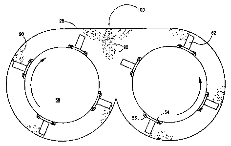
FIG. 12 shows that the collision location 100 is in the
space defined by the machine body top 28 and the two rotors
58. More specifically, the substantially head on
collisions 100 occur proximate the body top 28. The broken
pieces then drop into the channels 48. The impeller arms
52 continue to pick up the broken material and throw it at
similar material until the material is of a predetermined
size, at which point the particles 92 pass to the next
channel 48 from the machine body 20 by the discharge device
70 or a pressure differential. The particles 92 then
travel through the pipe 82 into a holding bin (not shown).
The material is moved through the machine body 20 by
the helical nature of the impeller arms 52 and the pressure
differential within the body 20. The graduated baffles 40
and the discharge baffle 46 serve to regulate the flow
based upon the desired size of the crushed material. Upon
entering the machine body 20, the material 90 has a first
size. After the first set of collisions, the material has
a second, smaller size. The helical configuration of the
impeller arms 52 draw the material towards the back end 26
of the machine body 20 much like an agricultural auger
moving grain or other powdered materials. If the broken
particles are too large, the height of graduated baffles 40
and the size of the slots 45 within the graduated baffles
40 prevent the broken particles from advancing past a
certain point. The broken particles are then carried by
the impeller arms 52 to another collision. Once the
particles created by the collisions are small enough, the
CA 02303349 2000-03-09
WO 99/12647 PC'T/US98/18689
pressure differential will draw them towards the back end
26 of the machine body 20 and over the graduated baffles 40
and the discharge baffle 96. The pressure within the
machine body 20, therefore, prevents the material 90 from
becoming too small. The net result of this arrangement is
a smoother flow of material than in conventional devices
relying on collisions with parts of the machine or cyclonic
turbulence.
The pulverizing system reduces material to a
predetermined size in a single pass trrough the machine
body 20. Utility companies typically require at least
seventy percent of a combustion mixture to pass through a
two hundred mesh sieve. Under this standard, at least
seventy percent of the mixture must have a particle size
less than seventy-four microns. The pulverizing system 11
is capable of producing mixtures that meet this standard.
For example, the current prototype has reduced a mixture of
seventy percent coal having a top size of one inch by one
inch and thirty percent wood having a top size of two
inches by one inch to meet this standard in a single pass
through the system in approximately two seconds or less.
The pulverizing system is also capable of reducing to a
predetermined particle size relatively large materials
whose top size is about four by four inches in the same
amount of time as it reduces smaller materials whose top
size is about one-fourth by one-fourth inches in a single
pass through the system. As a result, the capacity of the
pulverizing system is not decreased significantly when
larger top size material is processed.
Beca use the collision of the material happens W
the neutral space between the rotors, there is less wear on
16
CA 02303349 2000-03-09
WO 99/12647 PCT/US98118689
the internal parts of the system. In addition, because the
machine parts experience less wear, the pulverizing system
does not consume additional power to compensate for worn
parts, which makes the pulverizing system more efficient.
The central location 100 of the collisions results in
little accumulation of material below either rotor 58,
which would cause drag on one the shafts and thus reduce
the e'ficiency of the system. The colliding material 90
also experiences less rise in temperature due to breakage
than that produced by the friction created when material
collides with parts of the machine and is as eaually
effec~ive when the temperature of the exit material is
below one hundred and fifty degrees Fahrenheit. This
abili~y allows the pulverizing system to process materials
at lower temperatures, which is advantageous when the
material has a low combustion temperature.
The substantially head-on collisions, furthermore,
produce more spherical particles than conventional devices
because the impact of the material with other =lying
material weakens and dissolves the natural bonds betweer.
the molecules. Spherically-shaped particles burn more
evenly and leave less residue in the combustion chamber.
Therefore, mixtures processed by the pulverizing system 11
are attractive to power plants. Moreover, the distribution
of particle size is more uniform. FIG. 13 shows the
results of a Microtrac test conducted by the Department of
Energy. Wood and coal of various sizes were fed into the
pulverizing system to produce a mixture of wood and coal
part'_cles. The mixture was seventy percent coal and thirty
percent wood. FIG. 13 shows that the distribution of
particle size has approximately a Bell curve with the
median particle size being approximately 40 microns. The
17
CA 02303349 2000-03-09
WO 99112647 PCT/US98/18689
largest particles were about 500 microns and the smallest
particles about 1.5 microns. A uniform particle size
distributions advantageous because it enables the operator
to select a predetermined size with greater accuracy. In
addition, utility companies prefer mixtures having a
uniform particle size distribution because these mixtures
yield better combustion results. -
The pulverizing system is useful for crushing coal,
wood, biomass material, tires, and waste such as municipal
solia waste, agricultural waste, and hospital and
pharmaceutical waste, all of which may be burned to produce
power. In addition, the pulverizing system is capable of
mixing different materials, such as wood and coal, and
injecting additives to the mixture to improve its
combustion characteristics. The pulverizing system could
also be used to grind construction and demolition debris on
site, which could then be reused in asphalt. The
pulverizing system could be used to crush glass, plastic,
china, limestone, silicon chips, gypsum board, carbon, used
util=ty poles and railroad ties, and hazardous materials.
The pulverizing system could also be used in mining
operations to reduce ore and tailings as well as to recover
minerals.
The above description and drawings are only
illustrative of preferred embodiments of the present
invention, and are not intended to limit the present
invention thereto. Any modification of the present
invention which comes within the spirit and scope of the
following claims is to be considered part of the present
invention.
18