Note : Les descriptions sont présentées dans la langue officielle dans laquelle elles ont été soumises.
CA 02304139 2006-10-02
t l
CRN 227 PB
-1-
INTELLIGENT BRAKING SYSTEM FOR MATERIALS HANDLING VEHICLES
BACKGROUND OF THE INVENTION
The present invention relates in general to materials handling vehicles and,
more particularly, to methods and apparatus for braking such vehicles. While
the
present invention is generally applicable to materials handling vehicles, it
will be
described herein with reference to a rider reach fork lift truck for which it
is particularly
applicable and for which it is initially being utilized.
Braking of fork lift trucks may be accomplished through the use of a
mechanical brake, such as disclosed in U.S. Patent No. 5,057,728, or by
using the dynamic braking characteristics of the electric traction motor, such
as disclosed in U.S. Patent No. 5,340,202.
The brake shown in the '728 patent is a three-step brake; that is, the brake
is
capable of providing three levels of braking force, depending upon braking
requirements. Of course, mechanical brakes are subject to wear; therefore, to
reduce
wear, and since regenerative braking using the traction motor conserves
battery
charge, it is desirable to use the electric motor for as much of the braking
requirements as possible. On a rider reach fork lift truck, a single,
electrically
powered and steerable drive wheel is mounted on one corner of the power unit
of the
truck, and a caster wheel is mounted on the other corner. For some trucks, the
caster
wheel is also provided with a brake or a caster brake.
Thus, while motor braking and mechanical braking of the drive wheei and, in
some applications also mechanical braking of the caster wheel, are known for
materials handling vehicles, there is an ongoing need to improve the methods
and
apparatus which operate and coordinate these braking systems for improved
braking
performance. Such improvements would better adapt braking performance for
known
operating conditions of travel direction and allowable travel speed/fork
height,
distribute braking requirements between mechanical braking and regenerative
CA 02304139 2000-03-22
WO 99/16636 PCT/US98/19910
-2-
braking associated with the steerable drive wheel, use regenerative braking as
much
as possible, and engage the brake on the caster wheei in proper proportion to
the
brake on the drive wheel. Preferably, the improved braking control would be
computer controlled and hence be easily adaptable in the field and also enable
simplified manufacturing of materials handling vehicles utilizing the improved
braking
control.
SUMMARY OF THE INVENTION
This need is met by the invention of the present application wherein a
computer controlled braking system utilizes the gross vehicle weight of a
materials
handling vehicle and maximum allowable speeds of the vehicle to calculate
braking
force for the vehicle. The maximum allowable speed is determined based on the
direction of travel of the vehicle: forward, i.e., forks forward; and,
reverse, i.e., power
unit forward, and the height of load carrying forks of the vehicle. For
vehicles
equipped with a caster brake, the calculated braking force is proportionally
and
programmably distributed between a drive brake and the caster brake. The drive
brake includes a mechanical brake, which is used for braking the vehicle when
moving and also holding the vehicle when parked, and motor braking which is
performed by a traction motor which drives the drive wheel. The drive brake
force,
either the total calculated braking force or the drive brake portion of the
calculated
braking force if a caster brake is provided, is divided between the mechanical
brake
and the motor braking so that the motor provides as much braking as is
possible to
reduce wear on the mechanical brake and also to conserve battery power.
For vehicles equipped with a caster brake, the caster brake portion of the
calculated braking force is determined as a percentage or proportion of the
total
braking force. The percentage is programmable and can differ dependent upon
the
direction of travel of the vehicle. The caster brake portion is reduced to
zero or
clipped and reverts to the drive brake if it is below a minimum caster brake
force. In a
similar manner, if the caster brake force is calculated to be greater than a
maximum
*rB
CA 02304139 2000-03-22
WO 99/16636 PCT/US98/19910
-3-
caster brake force, the caster brake force in excess of the maximum caster
brake
force is clipped and reverts to the drive brake. A maximum caster brake
current can
be set to accommodate different brake hardware. A user of the vehicle can
select
adjustments to the calculated drive brake force and, if provided, can also
select
independent adjustments to the calculated caster brake force.
In accordance with one aspect of the present invention, a method for braking a
materials handling vehicle comprises setting a gross vehicle weight for the
vehicle,
determining a maximum allowable speed for the vehicle, detecting a service
brake
request and, upon receiving a service brake request, calculating braking force
for the
vehicle in response to the gross vehicle weight and the maximum allowable
speed.
The calculated braking force may then be converted into braking control
actions. The
step of determining a maximum allowable speed for the materials handling
vehicle
may comprise the steps of determining a height of materials handling forks of
the
vehicle, and correlating a maximum allowable vehicle speed with the height of
materials handling forks of the vehicle. The step of determining a maximum
allowable
speed for the materials handling vehicle may further comprise determining a
direction
of travel of the materials handling vehicle, and correlating the maximum
allowable
vehicle speed with the direction of travel of the vehicle.
The step of calculating braking force may comprise the steps of setting
braking
force for a materials handling vehicle equal to the gross vehicle weight
mu{tiplied by
0.03 times the maximum allowable speed for the materials handling vehicle, and
solving the resulting equation. To optimize brake performance for the
particular floor
conditions, the method may further comprise determining a user adjustment
setting
for the braking force, and adjusting the braking force with the user
adjustment setting.
Preferably, the materials handling vehicle has a drive wheel driven by a
traction motor and a mechanical brake associated with the drive wheel, and the
braking force is then divided between the two by determining a portion of the
braking
force to be performed by the mechanical brake, and a portion of the braking
force to
be performed by operation of the traction motor. The step of determining a
portion of
the braking force to be performed by operation of the traction motor may
comprise
ji
CA 02304139 2000-03-22
WO 99/16636 PCT/US98/19910
-4-
subtracting the portion of the braking force to be performed by the mechanical
brake
and a rolling resistance of the vehicle from the braking force. In that event,
if the
result of subtracting the braking force to be performed by the mechanical
brake and
the rolling resistance of the vehicle from the braking force is less than
zero, the
portion of the braking force to be performed by operation of the traction
motor is set to
zero.
If the vehicle has a caster brake in addition to a drive brake, the method may
comprise determining a caster brake portion of the braking force, and a drive
brake
portion of the braking force. The step of determining a caster brake portion
of the
braking force preferably comprises taking a percentage of the braking force as
the
caster brake portion of the braking force. The method may further comprise
taking a
first percentage of the braking force as the caster brake portion for vehicle
travel in a
first direction, and taking a second percentage of the braking force as the
caster
brake portion for vehicle travel in a second direction opposite to the first
direction.
The method may further comprise determining a user adjustment setting for the
caster brake portion, and adjusting the caster brake portion in accordance
with the
user adjustment setting. Also, the method may further comprise determining a
user
adjustment setting for the drive brake portion, and adjusting the drive brake
portion in
accordance with the user adjustment setting. Preferably, separate and
independent
user adjustments are available for the caster brake portion and the drive
brake
portion.
For caster brake operation, a minimum caster brake force may be set with the
caster brake portion being compared to the minimum caster brake force and set
to
zero if the caster brake force is less than the minimum caster brake force.
Similarly, a
maximum caster brake force may be set with the caster brake portion being
compared to the maximum caster brake force and set to the maximum caster brake
force if the caster brake force is greater than the maximum caster brake
force. The
determination of the drive brake portion of the braking force may comprise
subtracting
the caster brake portion of the braking force from the braking force.
Normally, the
caster brake is eiectrical and the method further comprises setting a maximum
caster
ii
CA 02304139 2000-03-22
WO 99/16636 PCT/US98/19910
-5-
brake current, and limiting current to the caster brake to the maximum caster
brake
current. In this way, a variety of caster brake hardware can be accommodated.
To
ensure vehicle stopping, a timer is started when the operating speed of the
vehicle
falls below a first given speed, such as 1 MPH, and, upon expiration of the
timer, if
the operating speed exceeds a second given speed, the mechanical brake is
fully
applied.
In accordance with another aspect of the present invention, a braking system
for a materials handling vehicle comprises a computer programmed to: determine
a
maximum allowable speed for the materials handling vehicle, and calculate
braking
force for the vehicle in response to a gross vehicle weight and the maximum
allowable speed. The gross vehicle weight is normally set in the computer;
however,
it can be changed if the truck is modified or change is otherwise necessary.
The
computer may be further programmed to determine a user adjustment setting for
the
braking force, and adjust the braking force with the user adjustment setting.
Preferably, the materials handling vehicle comprises a drive wheel driven by a
traction motor and a mechanical brake associated with the drive wheel, and the
computer is further programmed to: determine a portion of the braking force to
be
performed by the mechanical brake, and determine a portion of the braking
force to
be performed by operation of the traction motor.
When the materials handiing vehicle further comprises a caster brake, the
computer is further programmed to determine a caster brake portion of the
braking
force, and determine a drive brake portion of the braking force. The computer
can be
further programmed to determine a user adjustment setting for the caster brake
portion of the braking force, and adjust the caster brake portion of the
braking force
with the user adjustment setting. Similarly, the computer can be further
programmed
to determine a user adjustment for the drive brake portion of the braking
force, and
adjust the drive brake portion of the braking force with the user adjustment
setting.
Preferably, the computer is programmed to utilize separate and independent
user
adjustments for the caster brake portion and the drive brake portion.
CA 02304139 2000-03-22
WO 99/16636 PCTIUS98/19910
-6-
Where the materials handling vehicle has a drive wheel driven by a traction
motor and a mechanical brake associated with the drive wheel, the computer may
be
further programmed to: determine an operating speed of the vehicle, start a
timer
when the operating speed of the vehicle falls below a first given speed, upon
expiration of the timer determine whether the operating speed exceeds a second
given speed, and fully apply the mechanical brake if the operating speed
exceeds the
second given speed upon expiration of the timer.
It is, thus, an object of the invention of the present application to provide
computer control of braking force calculations and adjustments at the time a
service
brake request is received; to provide braking force calculations based on the
gross
vehicle weight of a materials handling vehicle and the maximum allowable speed
of
the vehicle in response to a service brake request; to have different braking
efforts
depending on the direction of travei in order to take advantage of the
difference in the
dynamic weight distribution that is a function of travel direction and
consequently be
able to optimize the braking performance (stopping distance) for each
direction of
travel; to adjust the individual wheel brake forces in order to optimize the
brake
performance for the particular floor condition; to properly proportion the
brake effort
between drive wheel and caster wheel brakes; and, to control the braking
effort in
accordance with the maximum allowable travel speed (which is a function of
fork
height and travel direction) in order to improve the dynamic feel of the truck
while
braking.
Other objects and advantages of the invention will be apparent from the
following description, the accompanying drawings and the appended claims.
BRIEF DESCRIPTION OF THE DRAWINGS
Fig. I is a perspective view of a rider reach fork lift truck incorporating
the
braking methods and apparatus of the present invention;
Fig. 2 is a side elevational view of the lift truck of Fig. 1;
CA 02304139 2000-03-22
WO 99/16636 PCTIUS98/19910
-7-
Fig. 3 is an perspective view of a power unit of the truck of Fig. 1, taken
from
the right rear of the truck;
Fig. 4 is a simplified block diagram of the control circuit of the present
invention; and
Fig. 5 is a flow chart illustrating operation of the braking methods and
apparatus of the present invention.
DETAILED DESCRIPTION OF THE INVENTION
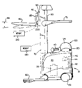
Figs. 1 - 3 show a rider reach fork lift truck 10 that includes a power unit
15
which includes an operator's compartment 20, a battery compartment 30, and a
motor
compartment 40. A battery 35, see Fig. 2, in the battery compartment 30
supplies
power to a traction motor 42 which is located in the motor compartment 40 and
connected to a steerable drive wheel 50 located at the left rear corner of the
power
unit 15 and to hydraulic motors (not shown) which supply power to several
different
systems within the truck 10. Attached to the motor 42 is a brake 44 and a
tachometer
46. A caster wheel 55 is mounted at the right rear corner of the power unit
15. A
conventional caster wheel brake 55a, see Fig. 4, is provided on some trucks. A
pair
of outriggers 60 support the front end of the truck 10.
In the operator's compartment 20 are mounted a steering tiller 100 for
controlling the direction of travel of the truck 10 and a control handle 110
for
controlling the speed of travel and the forward and reverse direction of the
truck 10 as
well as fork height, fork extension, and fork tilt and side-shift.
A mast assembly 70, mounted to the front of the power unit 15 of the truck 10,
includes an overhead guard 75. A pair of forks 80 are carried on a fork
carriage
mechanism 85 which is carried on extendable mast elements 90. The fork
carriage
mechanism 85 may include a reach mechanism 92 to allow the forks 80 to be
extended forward of the mast assembly 70, a side shift mechanism to permit the
forks
80 to be moved from side to side relative to the mast assembly 70, and a tilt
mechanism to permit the forks 80 to be tilted relative to the horizontal.
CA 02304139 2006-10-02
CRN 227 PB
-8-
As described in U.S. Patent 5,586,620, the reach mechanism 92 is
attached to the extensible mast assembly 70 by an assembly 94. A hydraulic
cylinder (not shown) is operated by the control handle 110 to control the
height of the forks 80. As shown in Fig. 2, the assembly 94 is raised. The
height of the forks 80 is measured by a digital encoder, represented at 190,
which may be similar to the device shown in U.S. Patent 5,103,226.
The forks 80 may be tilted through a range shown by the arrows 96 by means
of a hydraulic cylinder 200 located between the forks 80 and the fork carriage
85.
The weight of the load on the forks 80 is measured by a pressure transducer
210 that
is attached to a hydraulic line connected to the cylinder 200.
Also located within the operator's compartment 20, depending on the truck
model, may be a seat assembly 120 which is attached to the right side 122 of
the
power unit 15, as shown. When installed, the seat assembly 120 includes a back
rest
125, a seat 130, and a shelf 135. The seat assembly is vertically adjustable
for
operator comfort. An armrest 140 is also supported on the seat assembly 120
for
movement therewith.
On the floor of the operator's compartment 20 are two pedals 150 and 155.
The left-hand pedal 150 operates an electric switch to control braking of the
truck 10
while the right-hand pedal 155 operates a switch indicating the presence of
the
operator's foot thereon. Also located within the operator's compartment are
three
additional pedals: a pedal 160 which corresponds -to the pedal 150; a pedal
165
which corresponds to the pedal 155; and, a pedal 170 which is an additional
brake
pedal.
The operator must have one foot on and depress the pedal 150 or 160 in order
for the truck 10 to move; otherwise, the truck's brakes will be fully applied.
The
operator must also depress either pedal 155 or 165 in order for the truck 10
to move,
if it is stopped. If the truck 10 is moving, removal of the foot from the
pedals 155 or
165 will cause the truck 10 to coast. The switches controlled by pedals 155
and 165
are known as "presence" or "cut back" switches. Pedal 170 is an axillary brake
CA 02304139 2000-03-22
WO 99/16636 PCT/US98/19910
-9-
switch. Anytime the operator depresses pedal 170, the brakes of the truck 10
will be
immediately applied.
An operator's console 180 provides the operator with information regarding the
status of the battery voltage and may provide additional information including
indications regarding the fork height and the weight of the load on the forks
80.
The simplified block diagram of Fig. 4 shows various components used in
connection with the present invention which are associated with a
microprocessor
300 contained in a primary control module, referred to as the Access 3 module,
of an
electronic control system for the truck 10.
The truck 10 includes two braking modes. In the first mode, commonly
referred as "plugging," movement of the handle 110 in the direction opposite
to the
current direction of travel is recognized as a plugging request and results in
braking
by action of the traction motor 42. In the second mode, commonly known as
service
braking, the operator either removes the foot from pedals 150 or 160, or
depresses
the pedal 170. The methods and apparatus of the present invention perform
service
braking in response to a service brake request resulting in a combination of
regenerative braking performed by the traction motor 42 and mechanical braking
performed by the brake 44 and, if a caster brake is provided on the truck, by
the
caster brake.
In response to the service brake request, the invention of the present
application controls the braking of the truck 10 to improve truck braking
performance
by calculating the braking force to be applied using the gross vehicle weight
(GVW)
and the maximum allowable travel speed, which is dependent upon the travel
direction of the truck 10 and the height of the forks, at the time the service
brake
request is received. The allocation of braking effort between the mechanical
brake,
i.e., the brake 44, for the drive wheel 50, and regeneration braking of the
traction
motor 42 is optimized to reduce wear on the mechanical brake consistent with
the
ability of the motor 42 to provide the necessary braking torque. On those
trucks
equipped with a caster brake on the caster wheel 55, allocation of braking
effort
between the drive brake and the caster brake is also performed based on the
truck
CA 02304139 2000-03-22
WO 99/16636 PCT/US98/19910
-10-
weight distribution and coefficients of friction of the drive tire and the
caster tire.
Service braking operations of the invention of the present application, which
are
performed under the control of the microprocessor 300, will now be described
with
reference to Fig. 5.
When a service brake request is detected due to operation of one of the brake
pedals 150, 160 or 170, the total brake force is calculated based on an
American
National Standards Institute (ANSI) requirement:
Total Brake Force = (3 x V x GVW) / 100
where GVW is gross vehicle weight in pounds and V is the maximum allowable
speed
for the vehicle. For the present invention, the GVW used includes the total
unloaded
weight of the vehicle and the maximum rated load weight for the vehicle, i.e.,
GVW is
the total allowable fully loaded weight for the vehicle. And, V is the maximum
allowable speed in miles per hour (MPH) for the fully loaded vehicle. For
example, for
two different rider reach fork lift truck models of the RR5000 series of fork
lift trucks
manufactured by the Crown Equipment Corporation, one having a 42" wide power
unit and the other having a 48" wide power unit, the maximum allowable speed V
is
determined from the following table based on the direction of travel of the
truck and
the fork height:
CA 02304139 2000-03-22
WO 99/16636 PCT/US98/19910
-11-
Max Vehicle Speed in MPH
Fork 42" 42" 48" 48"
Height FF PUF FF PUF
<free 5.7 7.2 6.2 7.5
lift
>free 3.0 3.0 3.0 3.0
lift
<270"
CBH
>270" 1.5 1.5 1.5 1.5
CBH
where "FF" means Forks Forward, "PUF" means Power Unit Forward, free lift
refers
to a staging or collapsed height of the mast of the truck, and CBH refers to a
cutback
height above which the maximum allowable speed of the truck is reduced to a
creep
speed of 1.5 MPH.
The total braking force is split or divided between the drive tire and the
caster
tire based on known weight distribution and tire coefficient of friction.
Since the 42"
power unit has no caster brake, 100% of the braking is done by the drive tire.
The drive tire brake force or drive brake force is further split between motor
regenerative braking and the brake 44 or three-step friction brake on an
armature
shaft of the motor 42. The motor regenerative braking portion is made as large
as
possible, up to the practical torque output limit for regeneration. The
remaining
braking portion is performed by the three-step brake 44. The drive wheel
braking
force and the caster wheel braking force can each be further adjusted to
optimize
stopping distance for a particular floor condition. Adjustments are made by
the user
through operation of a display service menu on the operator's console 180 or
other
input device to the microprocessor 300.
il
CA 02304139 2000-03-22
WO 99/16636 PCT/US98/19910
-12-
Accordingly, when a service brake request is received by the microprocessor
300 from switches associated with one of the pedals 150, 160 or 170, for use
in
traction/brake control, see blocks 220, 222 of Fig. 5, the total brake force
(TBF) is
calculated, see block 224, using the equation:
TBF=GVWx.03XV
where GVW or gross vehicle weight is set equal to an allowable fully loaded
vehicle
weight and V is the maximum allowable vehicle velocity obtained, for example,
from
the above table by using fork height and direction of travel of the truck. By
using the
GVW of the truck to calculate the total braking force, all trucks with the
same
allowable speed will produce effectively the same stopping "g" force
regardless of
truck weights so that the trucks will stop in approximately the same distance
if
traveling in at the same speed and will have the same stopping "feel" when
service
braking is performed. The use of gross vehicle weight to calculate the total
braking
force also makes production of a variety of trucks more simple since the
brakes do
not need to be adjusted dependent upon the weight of the vehicles, as in the
past,
but will have appropriate braking forces due to the brake force calculation
aspect of
the invention of the present application.
After the total braking force is calculated, the caster share of the total
braking
force, i.e., the amount of braking force which is to be provided by the caster
brake of
the truck, is determined, see block 226. Of course, if no caster brake is
provided on
the truck, as is the case of the 42" wide truck, all the braking force is
applied by the
drive wheel brake 44. The caster share can be programmed into the
microprocessor
300 and can be set to different values depending on whether the truck is
traveling in
the forward direction (PERF), i.e., with the forks 80 forward, or in the
reverse direction
(PERR), i.e., with the power unit 15 forward. ln a working embodiment of the
invention of the present application, a default caster brake portion setting
of 25% is
utilized (PERF = PERR = 25%), due to the weight distribution of the truck 10,
with the
defauit brake portion being utilized for both forward and reverse directions
of travel.
CA 02304139 2000-03-22
WO 99/16636 PCT/US98/19910
-13-
However, any appropriate caster brake portion setting can be made as desired
or
necessary for a particular truck or operating conditions.
Due to variations in floor conditions and brake hardware, provision is made
for
adjusting brake forces to optimize braking conditions for a given application.
For
caster brake adjustments, user performance settings allow the user to adjust
the
caster brake force applied when the forks are below free lift. Thus, the user
selects a
multiplier which is used to modify the caster brake force. The multiplier can
range
from below one to above one with a series of nine stepped percentages ranging
from
approximately 62% to approximately 127% being utilized in a working embodiment
of
the present invention. Thus, the operator can select caster brake modifying
settings
(CSET) of 1 through 9 to optimize caster braking for floor or other operating
conditions.
A maximum caster brake value (CSTMAX) can also be set to accommodate
differences in brake hardware. If a caster brake value greater than the
maximum
caster brake value is selected, the caster brake value is set to the maximum
caster
brake value with the remainder of the requested caster brake value being
"clipped"
and transferred back to the drive wheel brake to maintain the total brake
force
calculated above.
A minimum caster brake value is also set (CSTMIN) and if a caster brake value
less than the minimum allowable caster brake value is requested, the caster
brake
value is set to zero with the clipped amount again being transferred back to
the drive
wheel brake to maintain the total brake force as calculated above. The caster
brake
also will not be applied if the forks are lifted above a maximum height or
caster height
(HT). For example, the caster height may be set to the cutback height or other
height
as required for a given truck.
In summary, an initial caster brake force (CST1) is calculated by taking the
caster brake percentage (PERC) of the total braking force. It is noted that
different
caster brake percentages can be used for forward travel (PERC = PERF) and
reverse
travel (PERC = PERR) of the truck:
CA 02304139 2000-03-22
WO 99/16636 PCT/US98l19910 _
-14-
CST1 = TBF x PERC
Next, any user adjustment is made by multiplying CST1 by the user adjustment
(CSET) to obtain a user modified or adjusted caster brake force (CST2):
CST2 = CST1 x CSET
The fork height is then compared to the caster height and, if greater than the
caster height (HT), a final caster brake force (CSET3) is set to zero:
CST3 = 0
The final caster brake force (CST3) is also set to zero if CST2 is less than
the
minimum allowable caster brake value (CSTMIN). If these instances do not
apply,
then CST2 is tested to see if it exceeds the maximum caster brake force
(CSTMAX)
and if so CST3 is set equal to the maximum caster brake force:
CST3 = CSTMAX
If none of these instances apply, then CST3 is set equal to CST2:
CST3 = CST2
Once the force to be applied by the caster brake CST3 has been determined,
the caster brake current (CSTAMP) or current to be appiied to the caster brake
must
be determined. The caster brake current is dependent upon the caster brake
hardware and can be calculated by the microprocessor 300; however, in a
working
embodiment of the invention of the present application a caster brake lookup
table is
utilized. For a specific caster brake used on the 48" truck the following
lookup table
applies:
CA 02304139 2000-03-22
WO 99/16636 PCTIUS98/19910
-15-
CSTAMP CST3
(Current) i (Force)
0 1 0
0.5 2 0
1.0 3 160
1.5 4 370
2.0 5 550
2.5 6 665
3.0 7 755
3.5 8 815
4.0 9 865
The caster brake current (CSTAMP) is determined by using the required caster
brake force (CST3) to enter the table and then interpolating within the table.
For
example, the caster brake force (CST3) may be compared to the table forces
until the
force read from the table is greater than CST3, i.e, if a caster force of 800
pounds is
required, an initial entry into the table is made at a force of 815 pounds (i
= 8) which is
greater than the required 800 pounds. Interpolation can then be performed by
subtracting the force at i -1 from the required force (800 - 755) and dividing
the result
by the force at i minus the force at i-1 (815 - 755) to obtain an
interpolation fraction
which is multiplied by the current difference from table entry i to table
entry i-1 to
obtain an interpolation current. The interpolation current is then added to
the caster
current vaiue at the i-1 entry to obtain the required caster brake current
(CSTAMP).
To accommodate caster brake hardware differences, a maximum caster
current value (CST MAXAMP) can be set so that the current to the caster brake
will
never go above the maximum caster current value. If CST3 is greater than the
highest caster brake force in the table, the caster brake current is then set
to the
maximum caster current value:
CA 02304139 2000-03-22
WO 99/16636 PCT/US98/19910
-16-
CSTAMP = CST MAXAMP
Having completed determination of the caster brake share for service braking,
the drive side share for service braking is determined, see block 228. The
drive side
brake force (BF) share is determined by subtracting the caster share of the
braking
from the total braking force (TBF) calculated above and adding back any
adjustments that were made due to limitations of the caster braking. More
particularly, the initial caster brake force (CST1) is subtracted from the
total braking
force (TBF) to find the original percentage of the total braking force to be
provided by
the drive side brake. Adjustments to the original percentage drive side
braking force
are calculated by subtracting the final caster brake force (CSET3) from the
adjusted
caster brake force (CST2) with the result being added to the original
percentage drive
side braking force to obtain the drive side brake force (BF).
As with the caster brake force, due to variations in floor conditions and
brake
hardware, provision is made for adjusting the drive brake force to optimize
braking
conditions for a given application. For drive brake adjustments, user
performance
settings allow the user to adjust the drive brake force applied when the forks
are
below free lift. Thus, the user selects a multiplier which is used to modify
the drive
brake force. The multiplier can range from below one to above one with a
series of
nine stepped percentages ranging from approximately 62% to approximately 127%
being utilized in a working embodiment of the present invention. Thus, the
operator
can select drive brake modifying settings (DSET) of 1 through 9 to optimize
drive
braking for floor or other operating conditions:
BF = [(TBF - CSTI) + (CST2 - CST3)] x DSET
Once the drive side brake force is finally determined, it has to be
distributed
between the motor 42 and the mechanical brake 44 with the motor 42 providing
as
much braking force as possible. To ensure that calculated braking forces do
not
exceed the capability of the braking devices, limits are placed on the
calculated
CA 02304139 2000-03-22
WO 99/16636 PCTIUS98/19910
-17-
braking forces. The maximum braking force that the mechanical brake 44 can
supply
is defined as parking brake maximum (PBMAX) and the maximum motor regeneration
braking force is defined as (SEMAX). The rolling resistance (RR) of the truck
is also
taken into consideration when calculating the drive side brake force with the
rolling
resistance of the truck being defined by:
RR=GVWX0.016
where GVW again is the gross vehicle weight which is set equal to the total
allowable
fully loaded vehicle weight.
The motor and friction or mechanical brake forces are then found by first
determining the minimum step brake (STEPBK) level (1/2, 2/3 or 3/3) required
to
keep the motor force from exceeding its limit (SEMAX), see block 230. Thus:
if (BF - (SEMAX + RR)) )(2/3) then STEPBK = 3/3; otherwise,
if (BF - (SEMAX + RR)) )(1/3) then STEPBK = 2/3; otherwise,
STEPBK = 1/3.
Next the motor torque setpoint is determined by subtracting a calculated step
brake force (STEPBK FR) and the rolling resistance (RR) from the drive side
brake
force (BF) and converting it to torque at the motor 42, see block 232.
MOTOR = (BF - STEPBK FR - RR) [if MOTOR ( 0 set MOTOR = 0]
where STEPBK FR = 0.132 x GVW x 1/3, 2/3 or 3/3.
BRAKE T = MOTOR x TORQUE CONVERSION CONST
where TORQUE_CONVERSION_CONST is a constant which converts braking force
at the tire to torque at the motor for a given vehicle and calculation of this
constant is
CA 02304139 2000-03-22
WO 99/16636 PCT/US98/19910
-18-
well known to those skilled in the art. For example, this constant for the
RR5000
series of fork lift trucks manufactured by the Crown Equipment Corporation is
calculated to be equal to 0.04315. Having determined the caster and drive
brake
forces, the brakes are applied, see block 234. The applied braking force is
maintained until the service brake request is terminated, see block 236, at
which time
the traction/brake control within the microprocessor 300 once again awaits the
next
service brake request, see block 220.
Since the motor regeneration torque begins to decay at speeds less than 1
MPH, the mechanical friction brake 44 (and the caster brake, if provided) are
required
to bring the truck 10 to a complete stop and hold it, for example when parked.
When
service braking is applied, the mechanical friction brake 44, or step brake
may be
applied at any of its three steps of braking (1/3, 2/3 or 3/3) with 3/3 being
the brake
step required to hold the truck 10 on a 15% grade. If the truck is braking on
a grade
and the step brake has been applied at a level less than 3/3, the truck may
not be
able of coming to a complete stop without additional braking from the brake
44.
Accordingly, a time out is provided to fully apply the step brake to 3/3 in
the event the
truck has not come to a complete stop within a given period of time.
After service braking is applied as described above, a timer
(TBRAMP_COUNT) is started when the speed of the truck falls below a given
speed
(BRFLIP_SPEED), for example 1 MPH. If the actual sped of the truck is greater
than
a programable speed (BRAKE_ZEROSPEED), for example 0 MPH, after
TBRAMP_COUNT times out, for example at 2 seconds, the brake 44 is applied at
its
full step value 3/3.
Having thus described the invention of the present application in detail and
by
reference to preferred embodiments thereof, it will be apparent that
modifications and
variations are possible without departing from the scope of the invention
defined in
the appended claims.