Note : Les descriptions sont présentées dans la langue officielle dans laquelle elles ont été soumises.
CA 02304231 2000-03-14
1 ~~
WO 00/08512 PCT/I1S99/17609
DISPLACED APERTURE BEAMSPLITTER FOR LASER
TRANSMITTER/RECEIVER OPTO MECHANICAL SYSTEM
Technical Field:
The present invention relates to an opto-mechanical system
incorporating a pair of transmitted laser beams and a received beam that share
common optics. The opto-mechanical system has particular utilities for
portable devices used for distance measuring applications.
Background of the Invention:
In a typical rangefinder application, the line-of-sight (LOS) of a high
quality visual optical path used for locating and identifying a target is
aligned
with the LOS of a second optical path associated with an eye-safe laser. The
eye-safe laser beam reflects off the target and becomes a return optical
signal
that is received along a path that is aligned with the transmitted eye-safe
laser.
A receiver detector senses the received beam to acquire information that can
be used to determine the distance to the object. The receiver detector, the
laser cavity optical system for producing the eye-safe laser beam, and the
visible aiming beam, produced by a laser diode and collimating optics, cannot
be mounted on an optical bench coaxially, they must be separated.
Prior art rangefinding applications typically use complex and expensive
multiple-bounce dichroic beamsplitters to yield coaxial laser transmitter and
aiming beam optical paths and separate the received laser beam from the
CA 02304231 2000-03-14
..
WO 00/08512 PCf/US99/17609
transmitted beams. Splitting the transmitted paths from the receiver path
typically requires dichroic optical coatings on the beamsplitter. Prior art
beamsplitters may require as much as four tightly toleranced regions of
different optical coatings. Prior art beam steering methods typically require
repackaging of the aiming light to accommodate complex beamsplitters with
added cost and weight to the overall opto-mechanical package.
Critical to rangefinder applications is the angular alignment of the three
laser beam paths must be held to tight tolerances. This places difficult
alignment and retention requirements on the optical elements typically used to
combine the two transmitted paths. For example, one laser is often transmitted
through a beamsplitter (usually tilted at 45E) and combined with the first
beam.
This causes the angular alignment sensitivity and retention of the
beamsplitter
to be twice as sensitive as the angular requirement between the two beams,
requiring costly optical alignment at manufacturing time.
In use, each of the two LOS paths must be steered from their respective
nominal position. The two LOS paths and the received path are manipulated in
unison in a manner that ensures that all paths have essentially the same
deviation from their nominal position. Prior art beam steering methods for
multi-wavelength systems require wedges or prism pairs for LOS steering.
Summary of the Invention:
The present invention is comprised of one eye-safe transmitted laser
beam, a visible transmitted light beam, and a single received laser beam that
all
share a single aperture ,optical system. The two pencil-thin transmitted beams
are co-aligned within 150 micro-radians in the same direction but have optical
CA 02304231 2002-05-07
3
axes that are displaced laterally. Lateral displacement of the two transmitted
beams eliminates the requirement for complex beam combining optics, which
relaxes the opto-mechanical tolerances. The in-coming beam is received along
a path that is essentially parallel with the path of the transmitted laser
beams
within 500 micro-radians. One variation of the present invention provides for
a
receiver path and detector for sensing the received laser beam. Other specific
variations of the present invention provide mechanical and optical methods for
expanding, aligning, and steering the three parallel beams as well as
separating
the in-coming receiver laser beam from the two out-going transmitted laser
beams. a
An exemplary embodiment of the present invention utilizes for one of the
out-going transmitted beams an infrared eye-safe laser having a wavelength of
1.533~,m. The second out-going transmitted beam is produced by a laser
diode in the visible red spectrum having a wavelength of 0.655p.m and is used
as an aiming light for .boresighting the unit to a weapon. The in-coming
received beam is the reflection or scattering of the transmitted infrared eye-
safe
laser beam off the target.
Due to the very small size of the transmitted beams in comparison to the
receiver aperture, a standard glass beamsplitter with anti-refection and
dichroic
coatings is not needed to separate the received beam from the transmitted
beams. In one variation of a specific embodiment, the small-aperture
transmitted beams each pass through a hole in a metal mirror beamsplitter that
is positioned to reflect a substantial amount of the received laser energy at
a
90° angle. The preferred embodiment of the beamsplitter is a simple
aluminum mirror with a thin highly reflective metallic coating with holes that
CA 02304231 2002-05-07
4
allow the laser transmitter and aiming beams to pass through the mirror. The
mirror provides about 98% reflectivity for the receiver beam and 100%
throughput for the transmitted beams. The beamsplitter has indexing features
that provide self-alignment of the beamsplitter to the laser mount, thereby
reducing optical alignment cost.
In another specific embodiment of the present invention, the out-going
transmitted beams are magnified by four times by Galilean telescope beam
expander optics. Magnification of the transmitted laser beams by the beam
expander optics allows for substantially smaller and lighter laser sources
than
would be possible without the beam expander optics. The two out-going
beams are transmitted through the top and bottom portions of the afocal beam
expander's optical aperture. The beam expander is also used by the receiver
path in conjunction with the beamsplitter, receiver lens and filter. The
objective
lens of the beam expander in the preferred embodiment is a cemented doublet,
comprised of a positive high-refractive-index crown lens having a bi-convex
shape and a very high-refractive-index flint lens having a meniscus-concave
shape. The negative lens "eyepiece" of the beam expander in the preferred
embodiment has a bi-concave-shape and is formed of a low-index crown glass.
The design of the afocal Galilean telescope beam expander optics is not a
conventional achromatic design. The novel aspects of the design of the beam
expander optics lie in the methods where the objective lens is specifically
achromatized at the 1.533~.m and 0.655pm wavelengths at the displaced
apertures of the two transmitted beams such that they exit the beam expander
telescope off-axis from the optical center line and maintain relative angular
alignment to within a few micro-radians. The design of the beam expander
CA 02304231 2002-05-07
optics also achieves a very flat wavefront (with almost no residual
aberrations)
for the full aperture of the receiver path to obtain the image quality
required at
the receiver detector. The Galilean telescope beam expander does not have
an intermediate image, thus the transmitted laser beam does not get
5 concentrated at a focus; this prevents ionization of the air.
In a specific embodiment of a rangefinder, the received beam passes
through a narrow band-pass filter for filtering out all wavelengths except the
desired 1.533~,m, and is focused by an aspheric glass lens that directs the
received beam energy onto a receiver detector. The receiver detector in the
preferred embodiment is a light detecting diode.
The optical system has the capability of being steered over a +/-
0.5°
field of view (FOV). The objective lens is movable in a plane orthogonal to
the
optical axis of the objective lens. In one exemplary embodiment, the
objective lens can be moved by as much as 0.775mm away from the initial
position of the optical axis for steering the transmitted beams and the
receiver
beam path up to an angle of 0.5E while maintaining the required angular
alignments between the two transmitted beams and the received beam.
According to one aspect of the present invention there is provided an
opto-mechanical system comprising:
a Galilean telescope beam expander including a large-aperture
objective lens and a negative lens defining an associated optical axis, for
receiving a large-aperture beam and first and second small aperture beams;
and
CA 02304231 2002-05-07
5a
a beamsplitter for separating said large-aperture beam from said
optical axis after said large-aperture beam has entered said objective lens
and has exited from said negative lens,
wherein said large-aperture beam has a first wavelength and
propagates in an in-coming direction along said optical axis;
said first small-aperture beam has said first wavelength and
propagates in an out-going direction opposite to said in-coming direction,
such
that said first small-aperture beam is displaced from said optical axis and is
transmitted from the negative lens to the objective lens through a first
peripheral portion of said Galilean telescope beam expander; and
said second small-aperture beam has a second wavelength different
from said first wavelength and also propagates in said out-going direction,
such that the second small-aperture beam is displaced from said optical axis
and from said first small-aperture beam and is transmitted through a second
peripheral portion of said Galilean telescope beam expander remote from said
first peripheral portion; and
wherein a respective external portion of each said small-aperture
beam out-going from said large-aperture objective lens are both essentially
parallel to an external portion of said large-aperture beam in-coming to said
objective lens.
According to another aspect of the present invention there is provided
an apparatus for determining the distance to a distant object comprising:
(a) a Galilean telescope beam expander including a large-aperture
objective lens and a negative lens defining an associated optical axis, for
receiving a large-aperture beam having a first wavelength propagating in an
CA 02304231 2002-05-07
5b
in-coming direction along said optical axis, wherein said large-aperature beam
has an external portion in-coming to said objective lens;
(b) means for providing a first small-aperture beam having said first
wavelength and propagating in an out-going direction opposite to said in
s coming direction, such that said first small-aperture beam is displaced from
said optical axis and is transmitted from said negative lens to said objective
lens through a first peripheral portion of said Galilean telescope beam
expander, and wherein an external portion of said first small-aperture beam
out-going from said objective lens is essentially parallel to said external
portion of said large-aperture beam in-coming to said objective lens;
(c) means for providing a second small-aperture beam having a second
wavelength different from said first wavelength and also propagating in said
out-going direction, such that said second small-aperture beam is displaced
from said optical axis and from said first small-aperture beam and is
transmitted through a second peripheral portion of said Galilean telescope
beam expander remote from said first peripheral portion, and wherein an
external portion of said second small-aperture beam out-going from said
objective lens is essentially parallel to said external portion of said large-
aperture beam in-coming to said objective lens; and
(d) a beamsplitter for separating said large-aperture beam from said
optical axis after said large-aperture beam has entered said objective lens
and has exited from said negative lens;
wherein said large-aperture beam is a reflection of said first small
aperture beam from said distant object.
CA 02304231 2002-05-07
5c
The methods of the present invention provide various opto-mechanical
system for rangefinding and boresight applications. Ruggedness, small size,
and light weight are significant advantages for applications that require
portability. Specific embodiments may have one or more advantages over
methods of prior art including: (1 ) less weight, (2) smaller physical size,
(3)
decrease in manufacturing cost, and (4) increased ruggedness.
CA 02304231 2002-05-07
6
Brief Description of the Drawings:
An embodiment of the present invention will now be described more
fully with reference to the accompanying drawings in which:
FIG. 1 shows a ray-trace diagram of the present invention.
FIGS. 2a and 2b shows a beamsplitter of the present invention.
FIG. 3 illustrates a method of the present invention for steering through
the LOS.
Detailed Description of Preferred Embodiments:
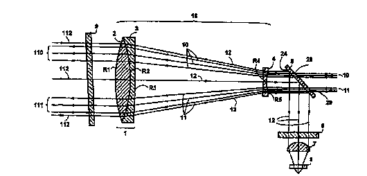
FIG. 1 shows a ray-trace diagram of an embodiment, which exemplifies
different specific aspects of the present invention. Transmitted laser beams
10, 11 pass through small holes 28, 29 in a metal mirror beamsplitter 5 and
are magnified by four times by Galilean telescope beam expander optics 18
comprised of an objective lens 1 and a negative lens 4. The transmitted
beams pass through respective top and bottom portions of the expander
optics 18 that have a close proximity to the periphery of the objective 1 and
negative 4 lenses. A received beam 12 is received through the aperture of
the objective lens 1, which is shared by the two out-going transmitted beams
10, 11. The external portions 110, 111 of both transmitted beams 10, 1 that
are out-going from the Galilean telescope beam expander optics have optical
axis that are essentially parallel to the optical axis of the external portion
112
of the received beam 12 that is in-coming to the shared Galilean telescope
beam expander optics. In FIGS. 1 and 3, the transmitted beam external
portions 110, 111 and the in-coming received beam external portion 112 are
shown in the ray-trace diagram as extending from surface R1 of the objective
CA 02304231 2002-05-07
6a
lens 1 through the sealing window 9. The eye-safe laser beam 10 has a
wavelength of 1.533~m, a diameter of 0.8mm prior to magnification and an
optical axis that is located 3.35mm from the optical axis of the beam expander
18. The aiming beam 11
CA 02304231 2002-05-07
7
has a wavelength of 0.655wm, has a diameter of 2mm prior to magnification,
and is located 2.77mm from the beam expanders 18 optical axis. The in-
coming laser beam 12 has a wavelength of 1.533~m and is received through
objective lens 1 of the beam expander optics 18 shared by the two transmitted
beams 10, 11. The received beam 12 is essentiaNy coaxial with the optical axis
of the beam expander 18 and has a diameter of 34.76mm.
An iterative process is used to design the afocal Galilean telescope
beam expander optics using a design and simulation computer software
program. Design and simulation programs are well known to those skilled in
the art. The essential program input parameters include the type of telescope,
the wavelengths of the transmitted and received laser beams, and that good
aberration correction is required.
In the exemplary design shown in Figure 1, the sealing window 9 is
formed of Schott BK7 glass and is 2.41 mm thick. The objective lens 1 of the
beam expander 18 is a cemented doublet comprised of a bi-convex shaped
lens 2 and a meniscus-concave lens 3. The bi-convex shaped lens is made of
a very high-refractive-index crown glass Schott LaKNl3. It has a thickness of
7.24mm along the optical center line, an outer radius R1 of 62.87mm, and an
inner radius R2 of -52.19mm that is equal to the inner radius of the meniscus-
concave lens. The meniscus-concave lens is made of a very high-refractive-
index flint glass Schott SFL6, has an outer radius R3 of -377.4mm, and a
thickness of 1.52mm along the optical centerline.
The negative lens 4 is located along the optical axis of the objective lens
62.74mm from the objective lens. The negative lens 4 is formed of low-index
25- crown glass Schott BK7 and has a bi-concave shape having a first radius R4
of
i
CA 02304231 2002-I05-07
8
-96.08mm, a second radius R5 of 13.07mm, and a thickness of 1.52mm along
the optical center line.
Energy from the received laser beam 12 is separated from the two
transmitted beams 10, 11 by a metal mirror beamsplitter 5. About 98% of
received beam energy is reflected off the metal mirror beamsplitter 5 and
passed through a narrow band pass filter 6 formed of a silicon substrate for
filtering out all wavelengths except the desired 1.533pm. An aspheric glass
lens 7 (Geltech part number 350240) focusses the energy of the received
beam 12 onto the receiver detector 8. The receiver detector 8 in the preferred
embodiment is a light detecting diode (EG&G part number 30718E).
In the exemplary embodiment shown in FIG. 1, the receiver detector 8
inlet path is essentially orthogonal to the optical axis of the beam expander
optics 18. A beamsplitter 5, positioned at a 45E angle from the optical axis
of
the beam expander optics 18, separates the received beam 12 from the two
transmitted beams 10, 11, and bends the received beam 12 path 90° into
the
receiver detector 8. An exemplary beamsplitter 5 of the present invention is
shown in FIG. 2. The beamsplitter 5 is preferably formed of aluminum 23 with a
thin nickel plating 21 on one surface that is optically polished to provide a
highly
smoothed surface 24. This nickel surface can then be coated with aluminum
with a further protective coating of SiOx or, alternatively, either plated
with gold
or coated with gold with a further protective coating of SiOx. Either process
results in a highly reflective mirror surface. Alternately, the beamsplitter 5
may
be formed of copper that is optically polished on one side 24 and then
overcoated with a protective layer of SiOX. Two small holes 28, 29 which are
oversized somewhat as compared to the diameter of the transmitted beams 11,
I
CA 02304231 2002-05-07
9
are formed in the metal mirrors to allow the two transmitted beams 11, 10 to
pass through. One specific embodiment utilizes an indexing feature 25 on the
beamsplitter 5 to achieve self-alignment of the beamsplitter 5 to a laser
mount,
eliminating costly manual optical alignment. Self-alignment is accomplished by
5 positioning the notch 25 on the beamsplitter 5 to a mating projection 30 on
the
laser mount such that the two orthogonal edges of the notch 25 are firmly
pressed against two respective surfaces of the projection 30 on the laser
mount. The two edges of the notch 25 and respective surfaces on the mating
projection 30 on the laser mount are accurately machined to a few micro-
10 meters to provide an accurate x-y location as well as accurate rotational
position of the beamsplitter 5 to the mount. The beamsplitter 5 can then be
rigidly bonded to three machined pads on the mount that are held to tight
tolerances to achieve a three-point kinematic attachment of the beamsplitter 5
on the laser mount.
Now referring to FIG. 3, a variation of the present invention provides the
capability for steering the LOS of both the transmitted 110, 111 and received
beam 112 over a +/- 0.5° field of view (FOV). The objective lens 1 is
movable
in all directions within the plane that is orthogonal to the optical axis of
the
objective lens 1. In the exemplary embodiment, the objective lens can be
moved by as much as 0.775mm away from the initial position of the objective
lens 1 for steering the external portions 110, 111 of the two transmitted
beams
10, 11, and the external portion 112 of the received beam 12 up to an angle of
0.5E from their respective nominal positions. The external portions 110, 111,
112 of the three beams maintain the required relative angular alignment. .FIG.
3 shows the objective lens 1 in a position displaced from the centered
position
CA 02304231 2000-03-14
WO 00/08512 10 .. PC'TNS99/17609-
1 such that the external portions of the in-coming beam 112'. and the external
portions of the transmitted beams 11 C and 111 each have an optical axis
that-is at a desired angle from their respective nominal positions 110, 111,
112.
The present invention, therefore, is well adapted to carry out arid attain
the advantages mentioned herein as well as other ends and advantages made
apparent from the disclosure. While preferred embodiments of the invention
have been described for purposes of disclosure, numerous changes and
modifications to those embodiments described herein will be readily apparent
to
those skilled in the art and are encompassed within the spirit of the
invention
and the scope of the following claims.