Sélection de la langue

Search

Sommaire du brevet 2304524 

Énoncé de désistement de responsabilité concernant l'information provenant de tiers

Une partie des informations de ce site Web a été fournie par des sources externes. Le gouvernement du Canada n'assume aucune responsabilité concernant la précision, l'actualité ou la fiabilité des informations fournies par les sources externes. Les utilisateurs qui désirent employer cette information devraient consulter directement la source des informations. Le contenu fourni par les sources externes n'est pas assujetti aux exigences sur les langues officielles, la protection des renseignements personnels et l'accessibilité.

Disponibilité de l'Abrégé et des Revendications

L'apparition de différences dans le texte et l'image des Revendications et de l'Abrégé dépend du moment auquel le document est publié. Les textes des Revendications et de l'Abrégé sont affichés :

  • lorsque la demande peut être examinée par le public;
  • lorsque le brevet est émis (délivrance).
(12) Brevet: (11) CA 2304524
(54) Titre français: SYSTEME DE PANNEAU A INDICATEUR D'ARRET INTEGRE
(54) Titre anglais: PANEL ASSEMBLY WITH INTEGRATED STOP SIGNAL
Statut: Périmé et au-delà du délai pour l’annulation
Données bibliographiques
(51) Classification internationale des brevets (CIB):
  • B60Q 01/30 (2006.01)
  • F21V 08/00 (2006.01)
(72) Inventeurs :
  • HIRMER, GERHARD F. (Canada)
(73) Titulaires :
  • DECOMA INTERNATIONAL INC.
(71) Demandeurs :
  • DECOMA INTERNATIONAL INC. (Canada)
(74) Agent: KERSTIN B. BRANDTBRANDT, KERSTIN B.
(74) Co-agent:
(45) Délivré: 2009-02-17
(86) Date de dépôt PCT: 1998-10-05
(87) Mise à la disponibilité du public: 1999-04-15
Requête d'examen: 2003-10-06
Licence disponible: S.O.
Cédé au domaine public: S.O.
(25) Langue des documents déposés: Anglais

Traité de coopération en matière de brevets (PCT): Oui
(86) Numéro de la demande PCT: 2304524/
(87) Numéro de publication internationale PCT: CA1998000942
(85) Entrée nationale: 2000-03-24

(30) Données de priorité de la demande:
Numéro de la demande Pays / territoire Date
60/060,961 (Etats-Unis d'Amérique) 1997-10-06

Abrégés

Abrégé français

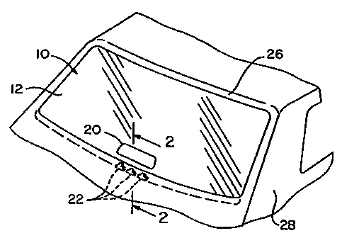
L'invention concerne un système de panneau (10) pour véhicule automobile, comprenant un panneau transparent (12) qui présente une première surface (14) et une seconde surface 816), qui sont opposées. Une partie de la première surface comprend une structure réfringente (18) faisant partie intégrante du panneau (12). Au moins une source lumineuse (22) est positionnée sur un bord du panneau afin d'injecter de la lumière dans ledit panneau (12). La surface réfringente (18) réfléchit la lumière émanant de la source lumineuse (22) à travers une partie de la seconde surface (16). Un laminé pelliculé (20) est positionné généralement de manière opposée à la structure réfringente (18). Lorsque la source lumineuse (22) est connectée de manière opérante au système de freinage du véhicule et que le laminé pelliculé (20) est rouge, le système de panneau (10) affiche un état de freinage.


Abrégé anglais


A panel assembly (10)
for an automotive vehicle has
a transparent panel (12) having
opposing first (14) and second
(16) surfaces. A portion of the
first surface includes refractive
structure (18) integral with the
panel (12). At least one light
source (22) is positioned at an
edge of the panel for introducing
light into the panel (12). The
refractive structure (18) reflects
light from the light source (22)
out through a portion of the
second surface (16). A film
laminate (20) is positioned
generally opposite the refractive
structure (18). When the light
source (22) is operatively
connected to a vehicle braking
system and the film laminate
(20) is red, the panel assembly
(10) will indicate a braking
condition.

Revendications

Note : Les revendications sont présentées dans la langue officielle dans laquelle elles ont été soumises.


Claims
What is claimed is:
1. A panel assembly (10) for an automotive vehicle comprising:
a transparent panel (12) having opposing first (14) and second surfaces (16),
a
portion of said first surface including a refractive structure (18) integral
with the
panel;
at least one light source (22) positioned at an edge of the panel for
introducing
light into the panel;
said refractive structure (18) constructed and arranged to reflect light from
said light source out through a portion of said second surface, characterized
by said
second surface having a red film laminate (20) positioned generally opposite
said
refractive structure.
2. A panel assembly as claimed in claim 1 wherein said transparent panel (12)
is a
molded plastic panel and said refractive structure (18) is molded therein.
3. A panel assembly as claimed in claim 2, wherein said light source (22) is
an LED.
4. A panel assembly as claimed in claims 2 or 3, wherein said plastic is a
clear
thermoplastic material selected from the group consisting of polycarbonate,
polymethyl methacrylate and cyclic polyolefin.
5. A panel assembly as claimed in claim 4 wherein at least one of said first
and
second surfaces (14, 16) is covered with an abrasion resistant coating.
6. A panel assembly as claimed in claim 5, wherein said abrasion resistant
coating is
a thermoset material selected from the group consisting of polysiloxane,
acrylic resin
and aliphatic polyurethane.
7. A panel assembly as claimed in claim 4 wherein said panel assembly (10) is
treated with a UV absorbing agent.
-4-

8. A panel assembly as claimed in any one of claims 1 to 7, wherein said
refractive
structure (18) is a multifaceted reflector.
9. A panel assembly as claimed in any one of claims 1 to 8, wherein said panel
assembly (10) is a rear window of the automotive vehicle.
10. A panel assembly as claimed in any one of claims 1 to 9, wherein said
light
source (22) is responsive to actuation of a braking system of the vehicle.
11. A method of producing a panel assembly (10) for a vehicle comprising:
molding a transparent panel (12) to have opposing first (14) and second
surfaces (16) such that a refractive structure (18) is defined in a portion of
said first
surface during molding;
providing a red film laminate (20) on a portion of the second surface; and
orienting at least one light source (22) along an edge of the panel,
characterized by said red film laminate (20) positioned so as to generally
oppose said
refractive structure (18) such that light emitted from said light source may
be reflected
by the refractive structure and passed through said red film laminate (20).
12. A method as claimed in claim 11, wherein said panel (12) is molded from a
plastic material selected from the group consisting of polycarbonate,
polymethyl
methacrylate and cyclic polyolefin.
13. A method as claimed in claim 12, wherein said molding step includes
molding
said refractive structure (18) in such a manner that said refractive structure
comprises
a plurality of facets in said first surface (14).
14. A method as claimed in claim 13 wherein the orienting step includes
securing
said at least one light source (22) within a bore defined in said edge.
-5-

15. A panel assembly (10) for use as a rear window of an automotive vehicle
comprising:
a transparent panel (12) having opposing, generally planar, first (14) and
second surfaces (16), a portion of said first surface including a refractive
structure
(18) having a plurality of facets formed integral with said panel;
at least one light source (22) positioned at an edge of said panel for
introducing light into said panel between said first and second surfaces;
said refractive structure (18) constructed and arranged to reflect light from
said light source against said facets and out through a portion of said second
surface,
characterized by said second surface having a red film laminate (20)
positioned
generally opposite said refractive structure for illumination by said
reflected light.
16. A panel assembly as claimed in claim 15 wherein said transparent panel
(12) is a
molded plastic panel and said refractive structure (18) is molded therein.
17. A panel assembly as claimed in claim 16, wherein said light source (22) is
an
LED.
18. A panel assembly as claimed in claim 17, wherein said plastic panel is a
clear
thermoplastic material selected from the group consisting of polycarbonate,
polymethyl methacrylate and cyclic polyolefin.
19. A panel assembly as claimed in claim 18 wherein at least one of said first
and
second surfaces (14, 16) is covered with an abrasion resistant coating.
20. A panel assembly as claimed in claim 19, wherein said abrasion resistant
coating
is a thermoset material selected from the group consisting of polysiloxane,
acrylic
resin and aliphatic polyurethane.
21. A panel assembly as claimed in claim 20 wherein said panel assembly (10)
is
treated with a UV absorbing agent.
22. A panel assembly as claimed in claim 21, wherein said refractive structure
(18) is
a multifaceted reflector molded integrally with said transparent panel (12).
-6-

23. A panel assembly as claimed in claim 22, wherein said light source (22) is
responsive to actuation of a braking system of the vehicle.
24. A method of producing a panel assembly (10) for use as a rear window of an
automotive vehicle comprising:
molding a one piece transparent panel (12) to have opposing, generally planar,
first (14) and second surfaces (16) such that a refractive structure (18) of a
plurality of
facets is defined in a portion of said first surface during said molding;
providing a red film laminate (20) on a portion of the second surface; and
orienting at least one light source (22) along an edge of the panel,
characterized by positioning the red film laminate (20) opposite the
refractive
structure (18) such that light emitted from the light source into the panel
and between
the first and second surfaces may be reflected by the refractive structure off
the facets
and passed through the red film laminate (20) for illumination by the
reflected light.
25. A method as claimed in claim 24, wherein said panel (12) is molded from a
plastic material selected from the group consisting of polycarbonate,
polymethyl
methacrylate and cyclic polyolefin.
26. A method as claimed in claim 25, wherein said molding step includes
molding
said refractive structure (18) in such a manner that said refractive structure
comprises
a plurality of facets in said first surface (14).
27. A method as claimed in claim 26 wherein the orienting step includes
securing
said at least one light source (22) within a bore defined in said edge.
-7-

Description

Note : Les descriptions sont présentées dans la langue officielle dans laquelle elles ont été soumises.


CA 02304524 2000-03-24
WO 99/17956 PCT/CA98/00942
PANEL ASSEMBLY WITH INTEGRATED STOP SIGNAL
Field of Invention
The present invention relates to a panel assembly for an automotive vehicle
and, more
particularly, to a panel assembly having an integrated stop signal which
indicates braking of the
vehicle.
Background of the Invention
In a typical vehicle, an upper stop light is generally centrally located near
and separate
from the rear window of the vehicle. The upper stop light generally includes a
box containing
a light bulb with a red filter (lens) facing rearwardly. The box is mounted on
the rear shelf of
the vehicle next to the rear window and at the base of the rear window. Such
construction
requires many parts which increases the manufacturing cost and assembly time
of the stop
light.
Summary of Invention
The disadvantages of the prior art may be overcome by providing a panel
assembly
having an integrated stop signal reducing the number of parts and thus the
manufacturing costs
and assembly time of the rear window and stop light combination.
According to one aspect of the invention, there is provided a panel assembly
for an
automotive vehicle which has a transparent panel having opposing first and
second surfaces. A
portion of the first surface includes refractive structure integral with the
panel. At least one
light source is positioned at an edge of the panel for introducing light into
the panel. The
refractive structure reflects light from the light source out through a
portion of the second
surface. A film laminate is positioned generally opposite the refractive
structure. When the
light source is operatively connected to a vehicle braking system and the film
laminate is red,
the panel assembly will indicate a braking condition.
According to another aspect of the invention, there is provided method of
producing a
panel assembly for a vehicle. The method comprises the steps of:
molding a transparent panel to have opposing first and second surfaces such
that a
refractive structure is defined in a portion of the first surface during
molding;
providing a film laminate on a portion of the second surface so as to
generally oppose
the refractive structure; and
orienting at least one light source along an edge of the panel such that light
errlitted
-1-

CA 02304524 2000-03-24
WO 99/17956 PCT/CA98/00942
therefrom may be reflected by the refractive structure and passed-through the
film laminate.
Brief Description of the Drawings
Fig. 1 is a perspective view of a panel assembly of the invention shown
mounted at the
rear portion of a vehicle; and
Fig. 2 is a cross-sectional view of the panel assembly taken along the line 2-
2 of Fig. 1.
Detailed Description of the Preferred Embodiment
Referring to the drawings, a panel assembly for an automotive vehicle is
shown,
generally indicated at 10, which embodies the principles of the present
invention.
The panel assembly 10 includes a transparent panel 12, preferably made from
molded
plastic, having a first surface 14 and an opposing, second surface 16. A
portion of the first
surface 14 includes refractive structure 18. In the illustrated embodiment,
the refractive
structure 18 is integral with the panel 12 and is formed during an injection
molding process.
The refractive structure may define a multifaceted reflector.
Preferably refractive structure 18 is generally rectangular or trapezoidal in
overall shape
and is comprised of a plurality of preferably parallel facets formed in panel
12 and extending in
the width direction of panel 12.
A film laminate 20 is provided on the second surface 16 at a position
generally opposite
the refractive structure 18. The laminate 20 is a thin, transparent film
formed of thermoplastic
material such as polycarbonate or polyester resin. The laminate 20 is also red
in color to
provide a brake light, as will be explained in more detail below.
As best shown in Fig. 2, at least one light source 22 is positioned at an edge
of the panel
12 for introducing light into the panel. In the illustrated embodiment, the
light source 22
includes at least one LED light source which is received in a bore 24 defined
in a bottom edge
of the panel. It can be appreciated, however, that the number of LED's
provided are dependent
upon the amount of light which is to be seen or emitted through the film
laminate 20. In the
illustrated embodiment, three LED's are provided. Moreover, LED's produced by
the Hewlet-
Packard company are preferred.
With reference to Fig. 2, light rays introduced edgewise into the panel 12
will traverse
the panel 12 so nearly parallel to the side faces of the panel that a high
percentage will be
transmitted within the panel and will not illuminate the faces of the panel.
Light rays which
strike the refractive structure 18, however, will be refracted or reflected
and dispersed,out of
-2-

CA 02304524 2000-03-24
WO 99/17956 PCT/CA98/00942
the planes of the panel's large faces 14 and 16. Accordingly, the ied film
laminate 20 will glow
brightly so as to be recognizable as a brake light.
The light sources are operably connected to the vehicle's braking system and
are thus
responsive in a conventional manner to a brake signal from the vehicle so that
the light sources,
and thus red film laminate 20, will illuminate upon application of the
vehicle's brakes.
As shown in Figs. 1 and 2, the panel assembly 10 may be utilized as a rear
window for
an opening 26 in a vehicle 28. In a rear window application, the panel
assembly 10 is sealingly
mounted with respect to the rear opening 26 in a conventional manner.
The material choice of the window is clear thermoplastic material taken from
the group
consisting of polycarbonate, polymethyl methacrylate, and cyclic polyolefm and
may include
an abrasion resistant coating 30. As mentioned above, the panel 12 and
integral refractive
structure 18 are integrally molded together in an appropriately shaped mold
assembly used in
conjunction with an injection molding process.
VWhile the coating 30 shown in Fig. 2 is applied to only second surface 16,
the coating
may be applied to either or both surfaces 14 and 16. The coating preferably
comprises a
thermoset material taken from the group consisting of polysiloxane, acrylic
resin, and aliphatic
polyurethane. The coating may be applied by placing a sheet of coating
material onto a surface
of the mold prior to the injection molding process, by dip coating the entire
fabricated panel, or
by spraying or flow coating one or both surfaces of the fabricated panel.
Additionally, the panel assembly 10 could be treated with a UV absorbing agent
to
resist UV damage. Such agents, including polydimethylsiloxane, could also be
added to or
included with the coating 30.
While the invention has been described in connection with what is presently
considered
to be the most practical and preferred embodiment, it is understood that the
invention is not
limited to the disclosed embodiment but, on the contrary, it intended to cover
various
modifications in the arrangements.
-3-

Dessin représentatif
Une figure unique qui représente un dessin illustrant l'invention.
États administratifs

2024-08-01 : Dans le cadre de la transition vers les Brevets de nouvelle génération (BNG), la base de données sur les brevets canadiens (BDBC) contient désormais un Historique d'événement plus détaillé, qui reproduit le Journal des événements de notre nouvelle solution interne.

Veuillez noter que les événements débutant par « Inactive : » se réfèrent à des événements qui ne sont plus utilisés dans notre nouvelle solution interne.

Pour une meilleure compréhension de l'état de la demande ou brevet qui figure sur cette page, la rubrique Mise en garde , et les descriptions de Brevet , Historique d'événement , Taxes périodiques et Historique des paiements devraient être consultées.

Historique d'événement

Description Date
Le délai pour l'annulation est expiré 2010-10-05
Lettre envoyée 2009-10-05
Accordé par délivrance 2009-02-17
Inactive : Page couverture publiée 2009-02-16
Inactive : Taxe finale reçue 2008-12-02
Préoctroi 2008-12-02
Un avis d'acceptation est envoyé 2008-06-04
Lettre envoyée 2008-06-04
Un avis d'acceptation est envoyé 2008-06-04
Inactive : Approuvée aux fins d'acceptation (AFA) 2008-04-10
Modification reçue - modification volontaire 2007-12-13
Inactive : Dem. de l'examinateur par.30(2) Règles 2007-06-19
Exigences relatives à la révocation de la nomination d'un agent - jugée conforme 2006-10-03
Inactive : Lettre officielle 2006-10-03
Exigences relatives à la nomination d'un agent - jugée conforme 2006-10-03
Demande visant la révocation de la nomination d'un agent 2006-09-12
Demande visant la nomination d'un agent 2006-09-12
Inactive : CIB de MCD 2006-03-12
Modification reçue - modification volontaire 2004-02-26
Lettre envoyée 2003-10-23
Requête d'examen reçue 2003-10-06
Exigences pour une requête d'examen - jugée conforme 2003-10-06
Toutes les exigences pour l'examen - jugée conforme 2003-10-06
Lettre envoyée 2000-12-21
Inactive : Transfert individuel 2000-11-20
Inactive : Lettre de courtoisie - Preuve 2000-07-28
Inactive : Page couverture publiée 2000-06-23
Inactive : CIB en 1re position 2000-06-16
Inactive : Correspondance - Transfert 2000-06-08
Inactive : Lettre de courtoisie - Preuve 2000-05-23
Inactive : Notice - Entrée phase nat. - Pas de RE 2000-05-17
Demande reçue - PCT 2000-05-12
Demande publiée (accessible au public) 1999-04-15

Historique d'abandonnement

Il n'y a pas d'historique d'abandonnement

Taxes périodiques

Le dernier paiement a été reçu le 2008-09-17

Avis : Si le paiement en totalité n'a pas été reçu au plus tard à la date indiquée, une taxe supplémentaire peut être imposée, soit une des taxes suivantes :

  • taxe de rétablissement ;
  • taxe pour paiement en souffrance ; ou
  • taxe additionnelle pour le renversement d'une péremption réputée.

Les taxes sur les brevets sont ajustées au 1er janvier de chaque année. Les montants ci-dessus sont les montants actuels s'ils sont reçus au plus tard le 31 décembre de l'année en cours.
Veuillez vous référer à la page web des taxes sur les brevets de l'OPIC pour voir tous les montants actuels des taxes.

Historique des taxes

Type de taxes Anniversaire Échéance Date payée
Taxe nationale de base - générale 2000-03-24
TM (demande, 2e anniv.) - générale 02 2000-10-05 2000-09-01
Enregistrement d'un document 2000-11-20
TM (demande, 3e anniv.) - générale 03 2001-10-05 2001-09-19
TM (demande, 4e anniv.) - générale 04 2002-10-07 2002-09-30
TM (demande, 5e anniv.) - générale 05 2003-10-06 2003-09-22
Requête d'examen - générale 2003-10-06
TM (demande, 6e anniv.) - générale 06 2004-10-05 2004-09-15
TM (demande, 7e anniv.) - générale 07 2005-10-05 2005-09-26
TM (demande, 8e anniv.) - générale 08 2006-10-05 2006-09-14
TM (demande, 9e anniv.) - générale 09 2007-10-05 2007-09-20
TM (demande, 10e anniv.) - générale 10 2008-10-06 2008-09-17
Taxe finale - générale 2008-12-02
Titulaires au dossier

Les titulaires actuels et antérieures au dossier sont affichés en ordre alphabétique.

Titulaires actuels au dossier
DECOMA INTERNATIONAL INC.
Titulaires antérieures au dossier
GERHARD F. HIRMER
Les propriétaires antérieurs qui ne figurent pas dans la liste des « Propriétaires au dossier » apparaîtront dans d'autres documents au dossier.
Documents

Pour visionner les fichiers sélectionnés, entrer le code reCAPTCHA :


Pour visualiser une image, cliquer sur un lien dans la colonne description du document. Pour télécharger l'image (les images), cliquer l'une ou plusieurs cases à cocher dans la première colonne et ensuite cliquer sur le bouton "Télécharger sélection en format PDF (archive Zip)" ou le bouton "Télécharger sélection (en un fichier PDF fusionné)".

Liste des documents de brevet publiés et non publiés sur la BDBC .

Si vous avez des difficultés à accéder au contenu, veuillez communiquer avec le Centre de services à la clientèle au 1-866-997-1936, ou envoyer un courriel au Centre de service à la clientèle de l'OPIC.


Description du
Document 
Date
(aaaa-mm-jj) 
Nombre de pages   Taille de l'image (Ko) 
Dessin représentatif 2000-06-22 1 8
Abrégé 2000-03-23 1 49
Description 2000-03-23 3 168
Revendications 2000-03-23 2 77
Dessins 2000-03-23 1 20
Revendications 2007-12-12 4 152
Dessin représentatif 2009-01-26 1 13
Avis d'entree dans la phase nationale 2000-05-16 1 193
Rappel de taxe de maintien due 2000-06-05 1 109
Courtoisie - Certificat d'enregistrement (document(s) connexe(s)) 2000-12-20 1 113
Rappel - requête d'examen 2003-06-08 1 112
Accusé de réception de la requête d'examen 2003-10-22 1 173
Avis du commissaire - Demande jugée acceptable 2008-06-03 1 165
Avis concernant la taxe de maintien 2009-11-15 1 170
Correspondance 2000-05-15 1 23
PCT 2000-03-23 11 395
Correspondance 2000-07-27 2 14
Correspondance 2006-09-11 2 45
Correspondance 2006-10-02 1 15
Correspondance 2006-10-02 1 16
Correspondance 2008-12-01 1 26