Note : Les descriptions sont présentées dans la langue officielle dans laquelle elles ont été soumises.
CA 02305752 2000-04-06
WO 99/20930 PCT1FI98/00804
BRANCH PIPE CONNECTION
The invention relates to a branch pipe connection, which connection
includes a locking ring to be placed in a hole made in a wall of a pipe or the
like, the smallest outer diameter of a flange of the locking ring being larger
than the largest diameter of the hole, a sleeve or a branch pipe arranged
against the locking ring, and a support flange situated between the pipe or
the
like and a shoulder of the sleeve or the branch pipe.
WO Patent Application 91/07619 shows a connection for
connecting a branch pipe to a sewage pipe. In the connection the end of the
branch pipe is pushed inside the single branch to produce a telescopic
connection. A sealing flange is arranged outside the connection and settled
tightly by heating on top of a corrugated pipe, for example. At the connection
point the ring stiffness of the sewage pipe is rather weak after the
connection
has been made. The connection is difficult to be produced and it cannot be
easily dismounted subsequently.
European Patent Application 0 506 181 discloses a pipe connection
where the pipe fitting is pushed to an opening made in a sewage pipe, where
the end of the pipe fitting inside the sewage pipe is expanded. It is rather
laborious and difficult to produce the connection and the connection cannot be
dismounted subsequently. Even in this case the ring stiffness of the sewage
pipe is rather weak at the connection point.
WO Patent Application 95110727 shows a pipe connection used
especially in association with relined sewage pipes. In the connection the
single branch is pushed inside the sewage pipe and the flange is fused on the
inner surface of the sewage pipe by electric heating. It is rather difficult
to use
the method and there may be problems with the durability of the connection
under severe conditions. The ring stiffness of the sewage pipe cannot either
be improved.
European Patent Application 0 268 543, U.S. Patent 4,627,648,
Finnish Patent 71,405 and French Patent 2,557,255 disclose various pipe
connections where a sleeve of the single branch is pushed inside a hole in the
sewage pipe. Afl these connections have it in common that the flange of the
single branch is sealed at its outer surface against the sewage pipe. The
solutions are difficult in structure and they are not suitable for connecting
a
branch pipe to a lightly constructed underground sewage and drainage pipe.
CA 02305752 2000-04-06
WO 99/20930 PCT/FI98/00804
2
European Patent Specification 0 623 200 shows a pipe connection
where a branch pipe to be mounted at an oblique angle is connected to a pipe
having a larger diameter. An aperture of elliptic shape is made in the pipe
having a larger diameter, in which case the largest diameter of the aperture
has to be larger than the smallest outer diameter of the flange of the branch
pipe. In this way the aperture will be relatively large and thus the structure
of
the pipe, ring stiffness, for example, will weaken.
UK Patent 2 120 340 teaches a pipe joint where an inner part
provided with a slit is first mounted through a hole made in the sewage pipe
inside the sewage pipe. The joint further comprises an external flange and a
shoulder to be screwed inside the inner part. The joint can also be made from
outside the sewage pipe but it is only intended for inside sewage pipes having
a smooth surface. Furthermore, as the joint is arranged to be sealed by means
of the outermost flange to the outer surface of the sewage pipe, the joint
cannot be applied to connect the branch pipe to a lightly constructed
underground sewage and drainage pipe whose outer surface has a varying
profile, because it is practically impossible to seal the surface by the
sealing of
the cited UK Patent. It is not useful to make a varying profile for the
sealing
because the shape of the required sealing would vary according to the location
of the hole to be made. The use of silicone or other sealing compounds does
not either ensure a sufficiently good result and it is also very difficult to
use
them.
It is an object of the present invention to produce a steady pipe
connection for connecting a branch pipe to a sewage pipe or the like.
The branch pipe connection of the invention is characterized in that
the locking ring forms a uniform ring and the locking ring is of a flexible
material for mounting the locking ring in the hole in the pipe or the like
from
outside the pipe or the like.
An essential idea of the invention is that the connection includes a
locking ring forming a uniform ring and a sleeve and a branch pipe which are
arranged against one another and which can be tightened in their axial
direction. The connection further includes a support flange to be placed
outermost. A further essential idea is that the locking ring is of such a
flexible
material that the locking ring can be placed inside the sewage pipe or the
like
through a hole made for the branch pipe, although the smallest outer diameter
of the flange of the locking ring is larger than the largest diameter of the
hole
CA 02305752 2000-04-06
WO 99/20930 PGT/FI98/00804
3
made for the branch pipe. An idea of one preferred embodiment is that the
pipe connection includes a sealing arranged between the inner surFace of the
sewage pipe or the like and the flange of the locking ring.
An advantage of the invention is that the connection can be made
to the sewage pipe or the like from outside. A further advantage is that by
means of the connection, the sewage pipe can be re-rounded and the ring
stiffness of the sewage pipe can be improved at the same time. The hole
made for the locking ring can be rather small. The connection also has a great
bending stiffness. The connection can be further dismounted and lightly
constructed underground sewage and drainage pipes can be sealed very
simply with it.
In the present application, the term 'lightly constructed underground
sewage and drainage pipe' refers to sewage pipes whose walls are provided
for example with ribbed flanges or corrugation to improve ring stiffness of a
sewage pipe to the effect that the actual wall of the sewage pipe is
reasonably
thin and the inner surface is substantially smooth but because of ribbed
flanges or corrugation its outer surface can have a varying profile.
The invention will be explained in more detail in the appended
drawings where
Figure 1 is a schematic sectional side view of a pipe connection of
the invention,
Figure 2 shows the mounting of a locking ring of the pipe
connection of Figure 1, and
Figure 3 is a schematic sectional side view of another pipe
connection of the invention.
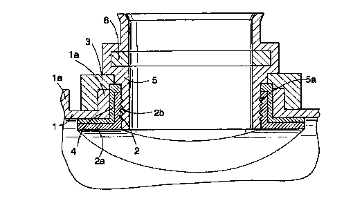
Figure 1 shows a pipe connection made to a lightly constructed
underground sewage and drainage pipe 1. The underground sewage and
drainage pipe 1 has ribbed flanges 1 a. The connection comprises a locking
ring 2 which forms a uniform ring and which has a flange 2a in the end which
is inside the underground sewage and drainage pipe 1. The outer diameter of
the flange 2a is larger than the diameter of the hole made in the underground
sewage and drainage pipe 1 for connecting the branch pipe. The hole can be
round or it can be slightly elliptical in shape, for example, in which case
the
smallest outer diameter of the flange 2a of the locking ring 2 is larger than
the
- 35 largest diameter of the hole. For this reason, the locking ring 2 is of
such a
flexible material that it can be momentarily compressed in one direction
CA 02305752 2000-04-06
WO 99/20930 p~'/Fl9g~ppg04
4
smaller than its normal circumference, in which case the locking ring 2 can be
mounted inside the underground sewage and drainage pipe 1 through a hole
made therein as shown in Figure 2. When the locking ring 2 is mounted inside
the pipe 1, it recovers its original shape. The pipe 1 can also be somewhat
flexible, in which case the possible hole therein can be slightly enlarged for
the
duration of mounting.
After the locking ring 2 is mounted, a support flange 3 is mounted in
the connection. After the support flange 3 is mounted, a sealing 4 of rubber,
for example, and after it a sleeve 5 are mounted. The locking ring 2 has inter-
nal threads 2b and the sleeve 5 similarly external threads 5a, in which case
the sleeve 5 can be threaded inside the locking ring 2. The sleeve 5 includes
a
shoulder arranged to be pressed above the support flange 3, in which case
when the sleeve 5 is threaded, it presses the support flange 3 against the
underground sewage and drainage pipe 1 from outside and the locking ring 2
against the underground sewage and drainage pipe 1 from inside.
The sealing 4 is arranged to be annular and extend from the inner
surface of the underground sewage and drainage pipe 1 as far as the sleeve
5. The upper surface of the sealing 4 against the sleeve 5 has a sliding
surface, because of which when the sleeve 5 is threaded, it slides on the
sealing 4 without substantially clinging to it. The lower part of the sealing
4 has
a flange arranged against the inner surface of the underground sewage and
drainage pipe 1. Instead of a uniform sealing 4, it is also possible to use
two
separate sealings, for example, to the effect that one sealing is between the
flange 2a and the inner surface of the pipe 1 and the other between the sleeve
5 and the upper edge of the locking ring 2. In pipes with a smooth outer
surface, it is possible to use instead of a sealing inside the pipe 1 an
external
sealing between the outer surface of the pipe 1 and the support flange 3.
The flange 2a can comprise means for fusing or welding the flange
to the inner 'surface of the pipe 1, in which case the sealing will be tight
and
steady. In addition to or instead of this solution, the sealing 4 can also be
arranged to form an electrofusion element.
The sleeve 5 is also provided with a recess to which a sealing 6 is
arranged for sealing the branch pipe inside the sleeve 5. The branch pipe is
not shown in the accompanying figures for the sake of clarity.
Figure 3 shows another pipe connection of the invention. The
numbering in Figure 3 corresponds to the numbering in Figures 1 and 2. The
CA 02305752 2000-04-06
WO 99/20930 PCT/FI98/00804
pipe connection of Figure 3 corresponds to the pipe connection of Figure 1 in
other respects except that the locking ring 2 is arranged somewhat higher and
the threads 2b are arranged on its outer surface. Correspondingly, the threads
5a to the sleeve 5 are arranged to the inner surface of the sleeve 5, in which
5 case the sleeve 5 is threaded to the outside of the locking ring 2. The pipe
connection is somewhat higher than the pipe connection of Figure 1, but in the
case of Figure 3 the hole made in the underground sewage and drainage pipe
1 can be of the same size as the outer diameter of the branch pipe.
The lower part of the sealing 4 has a similar flange as in the case of
Figure 1. At its upper end the sealing 4 has a conical part with a sliding
surface which allows the sleeve 5 to be rotated easily.
The drawing and the specification relating thereto are only intended
to illustrate the idea of the invention. In its details, the invention can
vary within
the scope of the present claims. For this reason, the sleeve 5 is not
necessarily required but instead, the end of the branch pipe can be formed to
correspond to the shape of the sleeve 5 shown in the figure. The threads 2b
and 5a can be omitted, when required, in which case any mechanical
connection or an adhesive joint can be arranged in their place. The sleeve 5
and the locking ring 2 can also have a uniform structure. This relates in
particular to solutions where the locking ring 2 is attached to the inner
surface
of the pipe or the like by welding or gluing. The outer surface of the sleeve
5
and the locking ring 2 can be clearly smaller than the diameter of the hole,
in
which case the fitting can be positioned into a suitable place with respect to
the hole. In Figures 1 and 3, the sleeve 5 is drawn perpendicular with respect
to the wall of the pipe 1. This is not necessary but the sleeve can also be at
another angle, such as 30° or 45° with respect to the wall of
the pipe 1. Most
preferably the locking ring 2 and the other parts of the connection are of
plastic, but when required, all parts can be of any material suitable for the
purpose. The flange 2a of the locking ring 2 can have a corrugated surface, in
which case it is also possible by means of the solution of the invention to
connect a branch pipe to a pipe having a corrugated inner surface. The scope
of the invention is not restricted to plastic pipes but the invention is
suitable for
connections of concrete and clay pipes with thick walls and vertical pipes of
drain well. By means of the solution of the invention, the branch pipe can be
connected, in addition to a pipe, to a tank having a curved surface or even
straight walls.