Sélection de la langue

Search

Sommaire du brevet 2306280 

Énoncé de désistement de responsabilité concernant l'information provenant de tiers

Une partie des informations de ce site Web a été fournie par des sources externes. Le gouvernement du Canada n'assume aucune responsabilité concernant la précision, l'actualité ou la fiabilité des informations fournies par les sources externes. Les utilisateurs qui désirent employer cette information devraient consulter directement la source des informations. Le contenu fourni par les sources externes n'est pas assujetti aux exigences sur les langues officielles, la protection des renseignements personnels et l'accessibilité.

Disponibilité de l'Abrégé et des Revendications

L'apparition de différences dans le texte et l'image des Revendications et de l'Abrégé dépend du moment auquel le document est publié. Les textes des Revendications et de l'Abrégé sont affichés :

  • lorsque la demande peut être examinée par le public;
  • lorsque le brevet est émis (délivrance).
(12) Demande de brevet: (11) CA 2306280
(54) Titre français: DETECTEUR DE CONDUCTIBILITE DE FLUIDE
(54) Titre anglais: FLUID CONDUCTIVITY SENSOR
Statut: Réputée abandonnée et au-delà du délai pour le rétablissement - en attente de la réponse à l’avis de communication rejetée
Données bibliographiques
(51) Classification internationale des brevets (CIB):
  • G01R 27/22 (2006.01)
  • G01N 27/02 (2006.01)
  • G01N 27/07 (2006.01)
(72) Inventeurs :
  • BROWN, NEIL L. (Etats-Unis d'Amérique)
(73) Titulaires :
  • FALMOUTH SCIENTIFIC, INC.
(71) Demandeurs :
  • FALMOUTH SCIENTIFIC, INC. (Etats-Unis d'Amérique)
(74) Agent: RICHES, MCKENZIE & HERBERT LLP
(74) Co-agent:
(45) Délivré:
(86) Date de dépôt PCT: 1998-09-29
(87) Mise à la disponibilité du public: 1999-04-15
Licence disponible: S.O.
Cédé au domaine public: S.O.
(25) Langue des documents déposés: Anglais

Traité de coopération en matière de brevets (PCT): Oui
(86) Numéro de la demande PCT: PCT/US1998/020374
(87) Numéro de publication internationale PCT: WO 1999018446
(85) Entrée nationale: 2000-04-06

(30) Données de priorité de la demande:
Numéro de la demande Pays / territoire Date
09/944,263 (Etats-Unis d'Amérique) 1997-10-06

Abrégés

Abrégé français

Détecteur de conductibilité de fluide qui effectue des mesures sans contact sur un fluide grâce à l'utilisation de premier et second tubes (32, 34) dont chacun est doté à la fois d'un transformateur d'alimentation (39) et d'un transformateur de détection (47). Les transformateurs d'alimentation sont polarisés de telle manière qu'ils introduisent un courant (I1, I2) dans une boucle joignant les deux tubes. Des écrans d'isolation (51) relient les extrémités correspondantes des deux tubes et fonctionnent pour bloquer le flux de courant à l'intérieur du fluide ne décrivant pas de boucle autour des tubes.


Abrégé anglais


A fluid conductivity sensor performs non-contacting measurements on a fluid by
utilizing first and second tubes (32, 34), each of which is provided with both
a driving and a sensing transformer (39, 47). The driving tranformers are
poled in such a way as to drive a current in a loop joining both tubes (I1,
I2). Insulating shrouds (51) are provided linking the corresponding end of the
tubes and operate to obstruct in-fluid current flow not looping around the
tubes.

Revendications

Note : Les revendications sont présentées dans la langue officielle dans laquelle elles ont été soumises.


7
CLAIMS
What is claimed is:
1. A fluid conductivity sensor comprising:
first and second tubes constructed of an insulating material
and adapted to be immersed in a conductive fluid so as to provide a
conductive path linking both tubes;
around each of said tubes, a respective first magnetic core
provided with a driving winding, said driving windings being
oppositely poled;
around each of said tubes a respective second magnetic core
provided with an output winding responsive to in-fluid current flow
linking both of said tubes thereby to reduce the electric field
extending into fluid and thereby reduce also the influence of objects
in a fluid in which said sensor is immersed.
2. A sensor as set forth in claim 1 wherein said tubes are parallel,
essentially identical and provide a central opening of circular cross-section.
3. A sensor as set forth in claim 1 wherein said windings are wound
toroidally on said cores.
4. A sensor as set forth in claim 3 wherein said cores are tape wound
of a high permeability magnetic material.

8
5. A fluid conductivity sensor comprising:
first and second tubes constructed of an insulating material,
said tubes providing generally similar and electrically parallel internal
paths;
around each of said tubes a respective first magnetic core
provided with a driving winding for inducing a current in a conductive
fluid linking that tube, said driving windings being oppositely poled;
around each of said tubes a respective second magnetic core
provided with an output winding for sensing current in a conductive
fluid linking that tube;
at least one shroud linking adjacent ends of said tubes, said
shroud being operative to obstruct in-fluid current flow not linking
both of said tubes thereby to reduce the influence of objects in a fluid
in which said sensor is immersed on induced currents sensed by said
output windings.
6. A sensor as set forth in claim 5 wherein said tubes are parallel
and essentially identical.
7. A sensor as set forth in claim 6 wherein said tubes are
constructed of a non-conducting ceramic.

9
8. A fluid conductivity sensor comprising:
first and second similar tubes constructed of an insulating
material and adapted to be immersed in a conductive fluid so as to
provide a conductive path linking both tubes;
around each of said tubes a respective first magnetic core
provided with a driving winding for inducing a current in a conductive
fluid linking that tube, said driving windings being oppositely poled;
around each of said tubes a respective second magnetic core
provided with an output winding for sensing current in a conductive
fluid linking that tube;
a first shroud linking one end of each of said tubes; and
a second shroud linking the other ends of said tubes, said
shrouds being operative to obstruct in-fluid current flow not linking
both of said tubes thereby to reduce the influence of objects in a fluid
in which said sensor is immersed on induced currents sensed by said
output windings.
9. A sensor as set forth in claim 8 wherein said tubes are parallel,
essentially identical and provide a central opening of circular cross-section.
10. A sensor as set forth in claim 9 wherein said windings are wound
toroidally on said cores and said cores are tape wound of a high
permeability magnetic material.

Description

Note : Les descriptions sont présentées dans la langue officielle dans laquelle elles ont été soumises.

CA 02306280 2000-04-06
WO 99/1844b PCT/(JS98/20374
1
FLUID CONDUCTIVITY SENSOR
BACKGROUND OF THE INVENTION
The present invention relates to fluid conductivity sensors, and more
particularly to a non-contacting fluid conductivity sensor which generates
essentially no external current field and thus is not influenced by nearby
objects in the fluid in which the sensor is immersed.
Industrial process control systems often require the measurement of
the electrical conductivity of a fluid e.g. seawater, used in the system.
Sensors for fluid conductivity measurement usually fall into one of two
categories, i.e, contacting sensors and non-contacting sensors. Contacting
sensors rely on a direct electrical contact between the measurement
electronics and the material to the fluid, while non-contacting sensors
typically employ driving and sensing transformers which, respectively,
induce and measure a flow of current in the conductive fluid, the
measurement of the induced current being a function of the conductivity of
fluid. One problem which has existed with existing non-contacting
conductivity sensors is that they may be influenced by objects a
considerable distance from the sensor in the body of fluid into which the
sensor is immersed. This influence is caused by the fact that conventional,
immersible sensors typically have an external current field which extends a
substantial distance from the sensor in the fluid in which the sensor is
immersed. This is a significant problem in that calibration performed
initially in the calibration laboratory will not be the same as calibration in
the field.
SUMMARY OF THE PRESENT INVENTION
The fluid conductivity sensor of the present invention employs first and
second tubes constructing of an insulating material. Around each of the
tubes is provided a respective magnetic core and driving winding for
inducing a current in a conductive fluid linking that tube. The driving
SUBSTITUTE SHEET (RULE 26)

CA 02306280 2000-04-06
WO 99/18446 PCT/US98I20374
2
windings on the two tubes are oppositely poled. Each of the tubes is also
provided with a second magnetic core having an output winding. Shrouds
are provided linking adjacent ends of the tubes, the shrouds being operative
to obstruct in-fluid current flow which does not link both of the tubes.
BRIEF DESCRIPTION OF THE DRAWINGS
Fig. 1 is a view, partially in section, of a prior art fluid conductivity
sensor;
Fig. 2 is a diagram illustrating the basic mode of operation of the
sensor of Fig. 1;
Fig. 3 is a side view in section of a fluid conductivity sensor in
accordance with the present invention;
Fig. 4 is an end view of the sensor of Fig. 3;
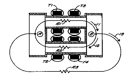
Fig. S is a diagram illustrating the equivalent resistances and current's
operative in the sensor of Figs. 3 & 4; and
Fig. 6 is a circuit diagram reflecting similar resistances and currents.
Corresponding reference characters indicate corresponding parts
throughout the several views of the drawings.
DESCRIPTION OF THE PREFERRED EMBODIMENT
Referring now to Fig. 1 which illustrates a prior art type of non-
contacting conductivity sensor, it may be seen that the sensor employs a
first magnetic core 11 provided with a toroidal driving or input winding 13.
The sensor also employs a second core 1 S with an output or sensing
winding 1 S. The two cores are aligned and coaxial and potted in an
incapsulating material 19 with an open central area 21 so that, when the
sensor is immersed in a conductive liquid, e.g. sea water, a current path
through liquid is established Which links the two magnetic cores 11 and 15.
Accordingly, when an AC voltage is applied to the winding 13, a current will
be induced in the conductive liquid, which current also links the core 15 so
that a corresponding current is induced in the output winding 17.
SUBSTITUTE SHEET (RULE 26)

CA 02306280 2000-04-06
WO 99/18446 PCT/US98/Z0374
3
The equivalent circuit is illustrated in Fig. 2, where the current path
linking the two cores 11 and 15 is shown as including a resistance Rw which
represents the sea water resistance, which is in turn a function of the
conductivity of the sea water. Accordingly, the current induced in the
output or sensing winding I7 is variable as the function of the conductivity
of the liquid. However, as is illustrated in Fig. 1, the current flow in the
sea
water extends, though at diminished intensity, for a considerable distance
from the sensor itself. Accordingly, objects in liquid can influence the
actual
value of Rw, either by displacing conductive liquid or by being more
conductive than the liquid itself.
In the sensor of the present invention illustrated in Figs. 3 and 4, there
are two tubes 31 and 33 constructed of a suitable insulating material, e.g. a
non-conductive ceramic. The tubes provide open central spaces, 32 and 34
respectively, of circular cross-section. As is explained in greater detail
hereinafter, the tubes are intended to be open to or immersed in the fluid
whose conductivity is to be measured. The two tubes are similar and
preferably essentially identical so that the fluid paths in the two tubes are
essentially parallel and will exhibit the same resistance end to end.
Each of the tubes 31 and 33 is provided with a first surrounding
magnetic core, 35 and 37 respectively, and each of these cores is provided
with a respective input or driving winding, 38 and 39 respectively. Each of
the tubes 31 and 33 is also provided with a second core, 41 and 43
respectively, having an output or sensing winding, 45 and 47 respectively.
The windings are preferably toroidaliy wound on high permeability tape
wound cores. An encapsulating material is provided as indicated at 61.
In operation the driving windings 38 and 39 on the two tubes are appositely
poled so that the current induced by one of the windings in the conductive
fluid in the respective tube will tend to return through the other tube. In
other words, when both the driving windings are energized, they will tend to
aid each other in inducing a current which links both of the tubes. While
the present invention is concerned principally with the design of the sensor
SUBSTITUTE SHEET (RULE 26)

CA 02306280 2000-04-06
WO 99/18446 PCTIUS98/20374
4
itself, which can be used with a variety of prior art driving and sensing
circuits, it is preferred that it the driving and sensing circuitry be of the
compensated feedback type described in coassigned U.S. Letter Patent
5,455,513 issued October 3, 1995 to Neil L. Brown and Alan J. Fougere.
While the outputs of the two sensing windings may be separately measured
and the results summed, it will typically be sufficient to connect the two
windings in series so their outputs add.
The adjacent left hand ends of the tubes 31 and 33 are linked or
coupled by a box-like shroud 51, which is also constructed of an insulating
material such as a non-conductive ceramic. The right hand ends of the
tubes 31 and 33 are coupled by a similar shroud 55. The shrouds 51 and
55 operate to obstruct any stray current which might tend to flow out into
the surrounding body of fluid into which the sensor is immersed, such as
might be caused by second order effects, e.g. the slight drop in potential
between the adj acent ends of the two tubes.
Fig. 5 illustrates the possible current paths through the conductive
liquid and the resistances associated with each. Fig. 6 is a circuit diagram
of the equivalent circuit showing the voltages induced in the conductive
liquid by the driving windings 38 and 39. Points A and B designate the
potential at the middle point in the body of liquid occupying each of the
shrouds 51 and 55 respectively. In Fig. 6, resistors are R1 and R2 represent
the resistances from A to B via the upper tube and lower tube respectively.
Resistor R3 represents the resistance from A to B via the liquid fluid path
external to the sensor structure. The voltages E 1 and E2 represent the
voltages induced by the windings 38 and 39. I, and Ia are the resulting
currents flowing in the upper and lower tubes.
It can be shown that if the ratio R 1 / E 1 is equal to the ratio R2 / E2 then
I i will be equal to I2. If the directions of I 1 and I2 are opposite, then
the
difference which flows externally will be zero. This means that the external
effects will be zero. Since the seawater in the two tubes has the same
conductivity and the dimensions are the same then the two resistances R1
SUBSTITUTE SHEET (RULE 26)

CA 02306280 2000-04-06
WO 99/18446 PCTNS98/20374
5
and R2 are the same. Transformers T 1 and T2 have identical windings and
are connected the same voltage, hence E 1 and E2 are assured of being
equal. The proof is as follows. If we assume that the potential at A is zero
then the following equations apply.
R2*R3 RI *R3
R2+R3 Rl+R3
Eb = EI * RI + R2*R3 + E2* R2+ RI *R
R2+R3 _3
Rl+R
3
R2 *R3 R 1 *R3
=EI * RI *R2+Rl *R3+R2*R3 +E2* R1 *R2+RI *R3+R2*R3
E1 *K+ E2 *K
R1 R2
Where K = R 1 *R2 *R3
R1 *R2+RI *R3+R2*R3
If E 1 = -E2 and R 1 = R2 then it is obvious that the above equations
equate to zero and that the voltage across R3 (i.e. the external path) is
zero.
In practice it may not be possible to insure that the two tubes are
identical. In this case the ratio of E 1 to E2 can be adjusted to
compensate for the inequality of R1 and R2 to maintain zero external field,
e.g. by providing slightly different levels of excitation to the two driving
windings.
In view of the foregoing it may be seen that several obj ects of the
present invention are achieved and other advantages results have been
attained.
As various changes could be made in the above constructions without
departing from the scope of the invention, it should be understood that all
SUBSTITUTE SHEET (RULE 26)

CA 02306280 2000-04-06
WO 99/18446 PCT/US98I20374
6
matter contained in the above description or shown in the accompanying
drawings shall be interpreted as illustrative and not in a limiting sense.
SUBSTITUTE SHEET (RULE 26~

Dessin représentatif
Une figure unique qui représente un dessin illustrant l'invention.
États administratifs

2024-08-01 : Dans le cadre de la transition vers les Brevets de nouvelle génération (BNG), la base de données sur les brevets canadiens (BDBC) contient désormais un Historique d'événement plus détaillé, qui reproduit le Journal des événements de notre nouvelle solution interne.

Veuillez noter que les événements débutant par « Inactive : » se réfèrent à des événements qui ne sont plus utilisés dans notre nouvelle solution interne.

Pour une meilleure compréhension de l'état de la demande ou brevet qui figure sur cette page, la rubrique Mise en garde , et les descriptions de Brevet , Historique d'événement , Taxes périodiques et Historique des paiements devraient être consultées.

Historique d'événement

Description Date
Inactive : CIB de MCD 2006-03-12
Demande non rétablie avant l'échéance 2002-09-30
Le délai pour l'annulation est expiré 2002-09-30
Réputée abandonnée - omission de répondre à un avis sur les taxes pour le maintien en état 2001-10-01
Inactive : Page couverture publiée 2000-06-22
Inactive : CIB en 1re position 2000-06-13
Lettre envoyée 2000-06-05
Inactive : Notice - Entrée phase nat. - Pas de RE 2000-06-05
Demande reçue - PCT 2000-05-29
Demande publiée (accessible au public) 1999-04-15

Historique d'abandonnement

Date d'abandonnement Raison Date de rétablissement
2001-10-01

Taxes périodiques

Le dernier paiement a été reçu le 2000-04-06

Avis : Si le paiement en totalité n'a pas été reçu au plus tard à la date indiquée, une taxe supplémentaire peut être imposée, soit une des taxes suivantes :

  • taxe de rétablissement ;
  • taxe pour paiement en souffrance ; ou
  • taxe additionnelle pour le renversement d'une péremption réputée.

Veuillez vous référer à la page web des taxes sur les brevets de l'OPIC pour voir tous les montants actuels des taxes.

Historique des taxes

Type de taxes Anniversaire Échéance Date payée
Enregistrement d'un document 2000-04-06
Taxe nationale de base - générale 2000-04-06
TM (demande, 2e anniv.) - générale 02 2000-09-29 2000-04-06
Titulaires au dossier

Les titulaires actuels et antérieures au dossier sont affichés en ordre alphabétique.

Titulaires actuels au dossier
FALMOUTH SCIENTIFIC, INC.
Titulaires antérieures au dossier
NEIL L. BROWN
Les propriétaires antérieurs qui ne figurent pas dans la liste des « Propriétaires au dossier » apparaîtront dans d'autres documents au dossier.
Documents

Pour visionner les fichiers sélectionnés, entrer le code reCAPTCHA :


Pour visualiser une image, cliquer sur un lien dans la colonne description du document. Pour télécharger l'image (les images), cliquer l'une ou plusieurs cases à cocher dans la première colonne et ensuite cliquer sur le bouton "Télécharger sélection en format PDF (archive Zip)" ou le bouton "Télécharger sélection (en un fichier PDF fusionné)".

Liste des documents de brevet publiés et non publiés sur la BDBC .

Si vous avez des difficultés à accéder au contenu, veuillez communiquer avec le Centre de services à la clientèle au 1-866-997-1936, ou envoyer un courriel au Centre de service à la clientèle de l'OPIC.


Description du
Document 
Date
(aaaa-mm-jj) 
Nombre de pages   Taille de l'image (Ko) 
Dessin représentatif 2000-06-22 1 11
Abrégé 2000-04-06 1 54
Description 2000-04-06 6 253
Revendications 2000-04-06 3 92
Dessins 2000-04-06 3 94
Page couverture 2000-06-22 1 43
Avis d'entree dans la phase nationale 2000-06-05 1 192
Courtoisie - Certificat d'enregistrement (document(s) connexe(s)) 2000-06-05 1 114
Courtoisie - Lettre d'abandon (taxe de maintien en état) 2001-10-29 1 183
PCT 2000-04-06 7 299
Correspondance 2004-04-30 46 2 876