Note : Les descriptions sont présentées dans la langue officielle dans laquelle elles ont été soumises.
CA 02306550 2000-04-06
WO 99/18010 PCT/GB98/03003
1 -
1 DISPENSING APPARATUS
2
3 This invention relates to dispensing apparatus.
4 Particularly, but not exclusively it relates to
dispensing apparatus for dispensing viscous materials
6 from a container under pressure of a propellant.
7
8 Known dispensing apparatus commonly includes a valve
9 mechanism fitted to a container which is refilled with
a product, for example mastic or sealant, which is to
11 be dispensed. Examples are disclosed in Patent
12 document EP-B-0243393 (Rocep Lusol Holdings Limited).
13 However, known arrangements have several disadvantages.
14
For example, the cost of components used in the
16 manufacture~of such known apparatus is high. This is
17 particularly true in relation to the cans used as
18 containers in such apparatus. Further, automatic
19 assembly of such apparatus is complicated and costly.
21 Yet another disadvantage is that the product must be
22 filled into the dispensing apparatus during manufacture
23 of the apparatus. This involves the product
24 manufacturer supplying the product in bulk to the
apparatus manufacturer who then returns the filled
CA 02306550 2000-04-06
WO 99/18010 PCT/GB98/03003
2 -
1 apparatus to the product manufacturer for sale. This
2 is costly and inconvenient. As a result of the
3 foregoing, the overall costs associated with presently
4 available dispensing apparatus are high.
6 Known dispensing apparatus, such as that disclosed in
7 EP-B-0089971 (Rocep Lusol Holdings Limited), include
8 piston arrangements which are designed to prevent
9 propellant gas in the apparatus from coming into
contact with the product to be dispensed. Commonly,
11 these piston arrangements consist of a pair of pistons
12 with sealant therebetween. However, known arrangements
13 can be costly to manufacture and have the significant
14 disadvantage that after filling of the apparatus, and
during storage, the sealant expands causing the pistons
16 to separate from one another. This problem has to be
17 addressed by "necking in" the can (ie locally reducing
18 the diameter of the can) below the piston assembly to
19 prevent separation. It would be desirable to have a
piston arrangement which would stay together without
21 the need for "necking in" the can.
22
23 It would also be desirable to have dispensing apparatus
24 such that a manufacturer can fill the apparatus with
product himself, after the apparatus has been assembled
26 and/or pressurised, and to have dispensing apparatus
27 which is refillable.
28
29 According to a first aspect of the present invention
there is provided dispensing apparatus for dispensing a
31 product from a container under pressure of a
32 propellant, said apparatus comprising a product chamber
33 within the container and a valve adjacent to the
34 product chamber characterised in that the valve allows
product flow into and out of the product chamber.
36
CA 02306550 2000-04-06
WO 99/18010 PCT/GB98/03003
3 -
1 Preferably, the product chamber is pressurised. The
2 product chamber preferably contains a piston, situated
3 between the propellant and the valve.
4
Preferably, the piston is an interlocking double
6 piston. The interlocking sections preferably have a
7 sealant between them. The sealant forms a
8 substantially impenetrable barrier between the
9 propellant and the product.
11 Preferably, the valve is operated by means of an
12 actuator and a lever. The lever may be manufactured of
13 plastics material; it may be manufactured as a single
14 piece of plastic, for example by injection moulding.
16 Preferably, the actuator and the lever co-operate by
17 means of a screw thread arrangement. Turning of the
18 actuator relative to the lever may vary the flow rate
19 of product out of the apparatus. Turning may be
possible from a "lock-off" position, in which the
21 actuator is clicked home, to a fully on position.
22 Markings may be provided to show the flow rate
23 corresponding to predetermined positions on the lever.
24
Means may be provided to demonstrate to a user that the
26 actuator is in the closed position, ie the position in
27 which no product can flow. It is further preferred
28 that the actuator is provided with means to limit the
29 travel of the actuator once the fully open position is
reached. Said means may also prevent the actuator from
31 being opened too far or being completely removed from
32 the apparatus. Said means may be a groove or
33 substantially axial slot in the external wall of the
34 actuator.
36 Preferably, the container is made substantially from
CA 02306550 2004-08-04
4
1 tin plate or aluminum. Most preferably the container is a wall
2 ironed tin plate can. For example, it may be an extruded tin
3 plate can as used in the beverage industry, without a side seam.
4
According to a second aspect of the present invention there is
6 provided a composite piston for use in a dispensing apparatus,
7 said composite piston comprising a first piston, a second piston
8 and a coupling means, the coupling means movably coupling the
9 first and second pistons to each other and permitting limited
relative movement between the first and second pistons in a
11 direction substantially parallel to the direction of movement of
12 the composite piston, wherein the coupling means comprises a
13 projection on one of the first and second pistons and a recess
14 in the other of the first and second pistons, and the projection
engages in the recess to couple the pistons to each other,
16 characterised in that the recess is a central aperture in one of
17 the first and second pistons and the projection is a central
18 projection on the other of the first and second pistons arranged
19 to engage the recess.
21 Preferably the first and second pistons interlock in use
22 defining a piston sealant chamber.
23
CA 02306550 2004-08-04
1 Preferably the piston sealant chamber is open circumferentially.
2
3 Typically, the projection is of a smaller dimension than the
4 recess to permit movement of the projection within the recess to
5 facilitate the limited relative movement of the first and second
6 pistons. Preferably, the projection and the recess include
7 mutually engageable ratchet formations which permit movement of
8 the pistons relative to each other in one direction only.
9 Preferably, the one direction is movement of the pistons towards
each other.
11
12 Preferably, the first piston and/or the second piston may be
13 elastically distorted to permit a push fit engagement of the
14 projection into the recess.
16 Typically, the pistons may be manufactured from a flexible
17 material, such as plastic.
18
19 Preferably, the composite piston also includes a viscous
substance which in use contacts the inside wall of a container
21 adjacent the composite piston. The viscous substance may help
22 to facilitate sealing of the composite piston against the inside
23 walls of the container and/or reduce friction between the
24 composite piston and the inside walls of the container.
CA 02306550 2004-08-04
1
6
2 Preferably the viscous substance is a sealant, such as a
3 glycerine and starch mixture. Preferably the sealant is adapted
4 to contact the interior surface of the container, thereby
forming a seal. This seal may be an annular ring of sealant in
6 contact with the container. This prevents propellant in the
7 apparatus from coming into contact with product in the
8 apparatus.
9
One or both of the primary and secondary portions may be
11 provided with an aperture and/or a valve to allow gas to escape
12 out of the sealant in use. Said valve may be a check
chamber
13 valve; it may be provided in a stem provided in the centre of
14 the secondary portion.
16 Preferably the piston assembly is provided with means for
17 accommodating expansion of the sealant, in use. This may help
18 prevent piston separation. Said means may be thinned portions
19 provided on the primary and/or secondary piston. Preferably,
said means is a plurality of thinned pockets in the wall of the
21 secondary piston. These pockets may balloon to accommodate
22 sealant expansion in use.
23
CA 02306550 2004-08-04
6a
1 According to a third aspect of the present invention there is
2 provided a container for dispensing a product therefrom, the
3 container comprising container walls, a composite piston
4 according to second aspect movably mounted within the container
and an outlet through which the product is dispensed, the
6 container walls and the composite piston defining a product
7 chamber within the container, and movement of the composite
8 piston within the container towards the outlet expelling product
9 through the outlet.
11 Typically, the viscous material is located between the first and
12 second pitons and may be forced into engagement with the inside
13 wall of the container by a compression force which acts between
14 the first and second pistons to cause the second piston to move
towards the first piston.
16
17 Preferably, the composite piston also includes a wall engaging
18 skirt which abuts against an inside wall of the container.
19
21 Preferably, a wall-engaging skirt is provided on both the first
22 and the second pistons.
23
CA 02306550 2004-08-04
6b
1 Preferably, the container is a pressure pack dispenser which
2 comprises propellant system which push es the piston towards
a
3 the outlet. However, alternatively, the piston could be used in
4 for use in combination with a mechanicalactuating device which
pushes the composite piston towards the outlet of the container.
6
CA 02306550 2000-04-06
WO 99/18010 PCT/GB98/03003
7 _
1 According to a fourth aspect of the present invention,
2 there is provided a container for use in dispensing
3 apparatus, said container comprising a hollow
4 cylindrical portion and a boss portion, said
cylindrical portion being open at one end for
6 attachment of a sealing dome and having a curled in
7 portion at the other end for engagement with a
8 corresponding flange provided on the boss portion.
9
Preferably, the cylindrical portion is made
11 substantially from tin plate or aluminium or other
12 suitable material.
13
14 Specific embodiments of the invention will now be
described, by way of example only, with reference to
16 the accompanying drawings in which:
17
18 Fig 1 is a side view in cross-section of
19 dispensing apparatus in accordance with an
embodiment of the present invention;
21
22 Fig 2 is an enlarged view of the valve area of the
23 apparatus of Fig 1;
24
2S Fig 3 is an enlarged view in cross-section of the
26 valve area of apparatus in accordance with another
27 embodiment of the present invention;
28
29 Fig 4 is an exploded view in perspective of the
apparatus of Fig 1 without a piston, nozzle or
31 overlap;
32
33 Fig 5 is a sketch of a lever mechanism for use in
34 the apparatus of Fig 1;
36 Fig 6 is a side view in cross-section of the
CA 02306550 2000-04-06
WO 99118010 PCT/GB98/03003
1 apparatus of Fig 1 during filling;
2
3 Fig 7 is an enlarged cross-sectional view of the
4 piston crown area of apparatus in accordance with
a preferred embodiment of the present invention at
6 the start of a fill cycle;
7
8 Figs 8a-8c are side views in cross-section of the
9 apparatus of Fig 1 during use;
11 Fig 9 is a cross-sectional view of the nozzle area
12 of apparatus in accordance with a further
13 embodiment of the present invention, adapted to
14 dispense predetermined doses of a product;
16 Fig 10 is a view in cross-section of a primary
17 piston of a piston assembly in accordance with the
18 present invention;
19
Fig 11 is a view in cross-section of a secondary
21 piston which cooperates with the primary piston of
22 Fig 10;
23
24 Fig 12 is a plan view of the top part of the wall
of the piston of Fig 11, showing the relative
26 thickness of each part of the wall;
27
28 Fig 13 is a side view in cross-section of
29 apparatus in accordance with yet a further
embodiment of the present invention, suitable for
31 "backward" filling;
32
33 Fig 14 is a cross-sectional view through a
34 container showing a composite piston in accordance
with another embodiment of the invention within
36 the container;
CA 02306550 2000-04-06
WO 99/18010 PCT/GB98/03003
9 -
1 Fig 15 is a cross-sectional view
through a lower
2 piston for use in the composite piston shown in
3 Fig 14;
4
Fig 16 is a cross-sectional view
through an upper
6 piston for use in the composite piston shown in
7 Fig 14;
8
9 Fig 17 is a cross-sectional view of the upper and
lower pisto ns of Figs 15 and coupled together
16
11 in a spaced apart position;
12
13 Fig 18 is a cross-sectional view of the upper and
14 lower pistons of Figs 15 and 16 coupled together
in a closed position;
16
17 Figs 19a-19d are side views in cross-section of
18 the apparatus in accordance with another
19 embodiment of the invention during use;
21 Fig 20 is a side view of the top part of apparatus
22 in accordance with the present invention, showing
23 an improved tamper seal arrangement; and
24
Fig 21 is a view in cross-section of the nozzle
26 end of apparatus in accordance with yet another
27 embodiment of the present invention.
28
29 Figs 22a and 22b are exploded views in cross-
section of the nozzle end of apparatus in
31 accordance with a further embodiment of the
32 present invention.
33
34 Referring firstly to Fig 1 of the accompanying
drawings, apparatus in accordance with an embodiment of
36 the present invention will be described. The apparatus
CA 02306550 2000-04-06
WO 99/18010 PCTlGB98/03003
1 will be referred to hereinafter as a "pressure pack" or
2 "pack". The pressure pack of Fig 1 is generally
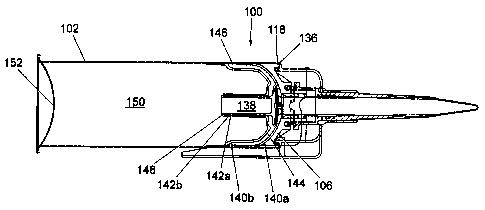
3 denoted 100.
4
5 The pack 100 consists generally of a canister section
6 and a valve section.
7
8 In this example, the canister section comprises a
9 standard preformed cylindrical can 102 which is
10 internally lacquered. It is envisaged that the can 102
11 could be a tin plate beverage can having a bore in the
12 top. Alternatively the can 102 could be manufactured
13 from aluminium.
14
The pack 100 is automatically assembled as follows,
16 with reference to Figs 1, 2 and 4 in particular of the
17 accompanying drawings.
18
19 Firstly a sub-assembly is formed from a valve portion
104, a boss 106 and an actuator 108, as will now be
21 described in more detail with reference to Figs 1, 2
22 and 4.
23
24 The valve portion 104 is a substantially hollow
cylindrical tube, provided with a screw thread 110 on
26 its exterior surface. The valve portion 104 is open at
27 one end (the top as viewed in Fig 2) and has a flap
28 valve 112 attached to its other end by means of a rivet
29 114. The valve portion 104 is also provided with, in
this example, four ports 116 around its exterior
31 surface adjacent the screw thread 110 (to the bottom of
32 ~ the screw thread 110 as viewed in Fig 2). It should be
33 noted at this stage that the flap valve 112 is made
34 from a rubber disc which preferably naturally lies in
the open position (ie not sealing the end of the
36 valve). This allows air to be expelled out of the
CA 02306550 2000-04-06
WO 99/18010 PCT/GB98/03003
11
1 pack, through the valve, during pressurisation. The
2 most preferred form of flap valve 312 is shown in
3 Fig 7. The flap valve 112 is shown in the closed
4 position in Figs 1 and 2. It should further be noted
that the total area of the ports 116 exceeds the cross-
6 sectional area of the valve portion 104 itself.
7
8 The boss 106 is a substantially hollow cylinder with a
9 large flange portion 118 at one end. The valve portion
104 fits snugly within the hollow of the boss 106. The
11 valve portion 104 is fitted into the boss 106 open-end-
12 first and is prevented from moving too far up the boss
13 106 by abutment of the shaped end profile 120 of the
14 valve portion against a corresponding portion I22 of
the boss I06. This can be seen in Fig 2, but is also
16 described later with reference to Fig 7. Further, the
17 valve portion 104 may be prevented from falling out of
18 the boss 106 by means of a clip 124 on the exterior of
29 the valve portion 104 which interacts with a slot (not
shown) in the interior surface of the boss I06. It
21 should be emphasised, however, that this is an entirely
22 optional feature.
23
24 The actuator 108 is a moulded plastic component having
a hollow cylindrical interior and a stepped exterior
26 surface. A screw thread 126 is provided on the
27 interior surface of the actuator 108.
28
29 Following insertion of the valve portion 104 into the
boss 106 (and clicking into place) the actuator 108 is
31 placed over the end of the valve portion 104 and
32 screwed onto it by means of cooperation of screw
33 threads 110 and 126. (An optional spring 128 may be
34 dropped into a groove 130 provided in the boss 106
prior to fitting the actuator 108. The spring 128 is
36 designed to close the valve if this does not happen
CA 02306550 2000-04-06
WO 99/18010 PCT/GB98/03003
12
1 automatically, as will be explained later.)
2
3 Screwing on the actuator 108 completes the sub-
4 assembly.
6 Referring now to Fig 3, for ease of understanding, the
7 reference numerals prefixed "1" are the same but
8 prefixed "2". In this embodiment, optional O-rings 232
9 may be provided in annular grooves around the valve
portion 204 either side of the ports 216. These O-
11 rings 232 help to form air-tight and product-tight
12 seals, respectively.
13
14 Rings 234 may also be provided on the surface of the
flap valve 212 end of the valve portion 204 where it
16 meets the boss 206. The rings 234 form air-tight
17 (plastic-to-plastic) seals between the boss 206 and the
18 valve portion 204, and the flap valve 212 and the valve
19 portion 204 when these components are in contact.
21 Referring again to Figs 1 and 2, the sub-assembly is
22 then inserted up the inside of the can 102 until the
23 flange 118 provided on the boss 106 fits into a curled
24 lip 136 at the top of the can 102. This limits further
movement of the boss 106. The boss 106 should be a
26 friction fit within the can 102, thereby sealing the
27 end of the can 102. However, if necessary the neck of
28 the can 102 may be crimped below the boss 106 to hold
29 the sub-assembly in place.
31 Following insertion of the sub-assembly, a double
32 piston assembly 138 is inserted into the can 102. The
33 piston assembly 138 comprises two interlocking plastic
34 cup sections 140a,b, each having a stem portion 142a,b
in its centre. The cup sections 140a,b lock together
36 and a cavity or chamber 144 is formed between them.
CA 02306550 2000-04-06
WO 99/18010 PCT/GB98/03003
13
1 The outer surface of the double piston assembly 138 is
2 in sliding contact with the internal surface of the can
3 102. The chamber 144 is filled with a measured
4 quantity of sealant to form a pressure seal. The
sealant not only fills the chamber 144, but also fills
6 the annular space 146 in contact with the internal
7 surface of the can 102.
8
9 The piston assembly 138 is formed by squirting sealant
(in this case glycerine and starch mix at +45°C) into
11 the first cup 140a or "first piston", then allowing the
12 sealant to cool and placing the second cup 140b or
13 "second piston" onto the first 140a. This is done
14 prior to insertion of the piston assembly 138 into the
can 102. As the second piston 140b is fitted into the
16 first 140a, the sealant is displaced within the cavity
17 144 formed between them. There is a minor "click" at
18 this stage as the pistons 140a,b engage each other.
19 Then the piston assembly 138 is rammed up the can 102
to the boss 106 and as this occurs the two pistons
21 140a,b are forced together. There is another "click"
22 as the pistons 140a,b then lock together by means of a
23 clip mechanism 148 on the stems 142a,b. At this second
24 click the sealant is displaced into the annular ring
146 to form a propellant-tight seal. Other methods of
26 interlocking the pistons and/or introducing the sealant
27 are envisaged.
28
29 This piston arrangement gives advantages over known
piston arrangements. For example,
the hollow stem
142b
31 of the second piston 140b permits to exit the space
air
32 between the first and second pistons 140a and 140b,
up
33 to the time when theylock together. In a modification
34 (not shown) piston could provided with a
the first be
central valve, to permit ir from above the
passage of
a
36 piston assembly.
CA 02306550 2000-04-06
WO 99118010 PG"T/GB98/03003
14 -
1 The volume 150 of the can 102 behind the piston
2 assembly 138 is now pressurised in the conventional
3 way, for example to 70 psi for a 47mm diameter can, and
4 an aerosol dome 152 fitted thereby sealing the pack
100. It is envisaged that, at this stage, the pack 100
6 will be supplied to the customer (ie a product
7 manufacturer) for filling, labelling and fitting of the
8 nozzle and the lever mechanism described below. The
9 product may be fixant, sealant, glue or the like.
Alternatively, it could be a foodstuff such as cake
11 icing, or a pharmaceutical, or a cosmetic product such
12 as depilatory cream.
13
14 At this stage, it should be noted that a small air
space 154 is left between the piston assembly 138 and
16 the valve 104. This can be seen, for example, in Fig
17 2. The airspace 154 is of a minimum size of 2ml and is
18 provided by shaping the crown of the piston 140a to fit
19 the valve profile and the boss 106 leaving the required
gap. Once the pack is pressurised, the increased
21 pressure against the flap valve keeps it in the closed
22 position.
23
24 Fig 6 is a view of the pack 100 during filling.
2S Filling may be done by a manufacturer of the product at
26 their own premises. A bulk pack of product (not shown)
27 is filled into the can 102 by means of a product fill
28 tube 156 in the direction of arrows B in Fig 6.
29
The tube 156 is inserted down through the interior of
31 the valve portion 104 until the end of the tube 156 is
32 adjacent the flap valve 112. (In a preferred
33 embodiment, as seen in Fig 7, a seal is formed around
34 the tube 356 by means of an O-ring 358.)
36 As product is introduced (for example, in excess of
CA 02306550 2000-04-06
WO 99/18010 PCT/GB98/03003
15 -
1 183 psi to fill a can at 70 psi) a small amount fills
2 the gap 154 between the piston 138 and the valve/boss
3 assembly. This product then begins to force the piston
4 assembly 138 down into the can 102 against the pressure
of the propellant in volume 150. The piston crown is
6 specially profiled to enable product to flow down over
7 the piston to enable this initial movement to occur. A
8 preferred design of piston 338 is also shown in Fig 7.
9
As the product continues to flow down the fill tube 156
11 the piston assembly 138 is forced down the can 102
12 toward the dome 152. Flap valve 112 is then able to
13 return to its natural position, ie the open position,
14 and further product flows into the volume 160 between
the piston crown and the boss/valve. This filling
16 continues until the required product fill is achieved
17 or the piston 138 reaches the dome 152 (ie as seen in
18 the view of Fig 8a) whichever is sooner.
19
The customer can then affix a label or other
21 identifying feature to the filled can 102 and then a
22 lever cap 162 is placed over the protruding parts of
23 the boss 106, the valve 104 and the actuator 108. The
24 lever cap 162 is shown in Fig 5 and is provided with
snappers 164 around its bottom edge. These snappers
26 164 are resiliently formed and once "snapped" into
27 place co-operate with the lip 136 of the can 102 to
28 hold the lever cap 162 securely in place.
29
The lever cap 162 is moulded as a single piece of
31 plastic and has a handle 166 and a base 168. The
32 handle 166 is joined to the base 168 by means of a
33 butterfly hinge 170. The handle 166 and base 168 are
34 each provided with overlapping apertures 172 through
which parts of the valve portion 104 and the actuator
36 108 protrude when the lever cap 162 is in place. The
CA 02306550 2000-04-06
WO 99/18010 PCT/GB98/03003
16 -
1 handle 166 is folded over on the hinge 170 so that
2 these apertures 172 overlap. Fig 4 shows various parts
3 of the pack 100 exploded. In Fig 4 the lever cap 162
4 is shown in the open (ie moulded) position.
6 The lever cap 162 is shown in place in Fig Sa, for
7 example. The pack 100 is completed with a nozzle 174
8 and a protective end cap (see 276 in Fig 3, for
9 example) which is fitted after the lever cap 162. The
nozzle 174 is screwed onto an external screw thread 178
11 provided on the actuator 108. Different lengths of
12 nozzle may be used if required.
13
14 The lever cap 162 may also be provided with a seal
mechanism 180 (as can be seen in Figs 8a-8c). The seal
16 180 prevents unwanted movement of the lever handle 166
17 prior to first use and serves as an indication of any
18 tampering.
19
Referring now to Figs 8a-8c, the pack 100 is shown in
21 Fig 8a in the form in which it is retailed. Volume 160
22 is filled with product and the handle 166 of the lever
23 162 is in the fully closed position. Seal 180 is still
24 intact. The lever handle 166 rests on a flange 182
provided around the bottom of the actuator 108. An
26 actuating knuckle 184 on the handle 166 contacts the
27 flange 182. The knuckle 184 can be seen in Fig 5.
28
29 To dispense product, the seal 180 is broken, the end
cap is removed and the nozzle 174 is cut open. The
31 actuator 108 is then twisted relative to the valve
32 portion 104 on screw thread 110. The screw thread is
33 preferably an acme triple thread. Typically one 360°
34 turn will fully open the pack 100.
36 The broken seal 180 can be seen in Fig 8b. An
CA 02306550 2000-04-06
WO 99/18010 PCT/GB98/03003
17
1 alternative seal arrangement could be provided on the
2 pack, as sold, consisting of an anti-tamper tab. This
3 tab could be a piece of plastic adapted to attach to
4 the lever handle and fit within one of the grooves 190
described below. when attached, abutment of the seal
6 against the side of the groove prevents turning of the
7 actuator relative to the lever handle and also prevents
8 lifting of the lever handle. The seal is broken by a
9 user pulling off the piece of plastic prior to use of
the pack. This seal may be provided on the dog tooth
11 188 described below, for example.
12
13 As the actuator 108 turns, the lever handle 166 lifts
14 on the hinge 170 due to the action of the actuator
flange 182 against the actuating knuckle 184. This can
16 be seen in the view of Fig 8b. The greater the flow
17 rate of product required, the more the lever handle
18 should be raised prior to use. The spring 128 is
19 extended at this point.
21 To dispense product, a user then presses down on the
22 lever handle 166 (moving it toward the body of the can
23 102). This pushes the actuator 108 and the valve 104
24 (which is attached to the actuator 108 via their
cooperating screw threads 110,126) down relative to the
26 boss 106. This is the position seen in Fig 8c.
27 Product is then urged to flow, by virtue of the
28 internal pressurisation of the pack 100 against the
29 piston 138 which then moves up toward the valve 104
forcing product from volume 160 through the ports 116
31 and up through the valve portion 104 and out through
32 the nozzle 174 (in the direction of arrows A in Fig
33 8c). Because the area of the ports is greater than the
34 bore diameter, the flow rate is the same as with
conventional packs. Backfill is also possible for this
36 reason.
CA 02306550 2000-04-06
WO 99/18010 PCT/GB98/03003
18 -
1 To stop dispensing, the user simply releases the lever
2 handle 166. This closes the valve by allowing it to
3 slide back up the bore and closing access through the
4 ports 116. If a spring 128 is included in the pack, it
will urge the valve closed, but in many cases the
6 internal pack pressure will close the valve reliably,
7 without the need for a spring.
8
9 The greater the angle between the lever handle 166 and
the can 102 prior to dispensing, the greater the
11 possible torque on the actuator/valve and hence the
12 greater the flow rate obtained from the pack 100.
13 Markings may be provided (by moulding for example) on
14 the side face 186 of the lever handle 166 which
indicate the flow rate that will be achieved when
16 depressing the handle 166 from that lever angle.
17
18 The lever 162 is also provided with a dog tooth 188 on
19 the interior of the aperture 172 in the lever handle
166. This dog tooth 188 is designed to fit into slots
21 or axial grooves 190 (see Fig 4) provided adjacent the
22 top of the actuator 108. If the actuator 108 is
23 unscrewed and the lever handle 166 rises sufficiently,
24 the dog tooth 188 engages in one of these grooves 190
and butts against the side of the groove 190 to prevent
26 further turning. In this way, the actuator/valve
27 cannot be fully removed from the pack.
28
29 In addition, the flange 182 of the actuator 108 is
provided with a projection 192 on its lower surface.
31 This projection 192 can be seen in Fig 2 and is
32 designed to click into one of a set of corresponding
33 indents (not shown) provided at equal intervals around
34 a ring on the top surface of the boss 106 when the
actuator 108 reaches the fully closed position. This
36 indicates to a user that the actuator 108 is "locked-
CA 02306550 2000-04-06
WO 99/18010 PCT/GB98/03003
19 -
1 off".
2
3 Embodiments of the invention are envisaged whereby
4 product can be dispensed in a predetermined dose.
Doses may be adjusted by adjusting the nozzle length.
6
7 Part of one such embodiment can be seen in Fig 9 of the
8 accompanying drawings. The apparatus of Fig 9 is
9 substantially identical to that already described, but
is provided with a return spring 194 and a piston/valve
11 assembly 196 within the interior of the nozzle 174,
12 valve 104 and actuator 108. Fig 9 shows the actuator
13 108 in the fully closed position.
14
The piston/valve assembly 196 is in the form of a
16 cylindrical hollow cage which is a sliding fit within
17 the interior of the nozzle, etc. The assembly 196 is
18 provided with a one-way valve 198 at the end nearest
19 the spring 194. In this embodiment, the first time the
lever handle 166 is raised and depressed, product is
21 forced up behind the cage, and the pressure then forces
22 the piston/valve assembly 196 toward the nozzle end
23 (the valve 198 remaining closed). This in turn
24 compresses the return spring 194. When the handle 166
is released, the spring 194 forces the assembly 196
26 back down, the valve 198 being open in this phase,
27 thereby leaving a dose of product (which passes through
28 the cage and the open valve) within the interior of the
29 nozzle, etc. To dispense the dose, the handle 166 is
raised and depressed again. This action simultaneously
31 "refills" the interior with a further dose of product
32 for the next application. This procedure can be
33 continued until the apparatus is empty. An end cap
34 (not shown) protects the dose from exposure to the
atmosphere when the apparatus is not in use. It is
36 envisaged that apparatus having the features shown in
CA 02306550 2000-04-06
WO 99/18010 PC'T/GB98/03003
20 -
1 Fig 9 would be particularly suitable for dispensing of
2 pharmaceuticals and the like.
3
4 The components of a preferred piston assembly will now
be described with reference to Figs 10, 11 and 12.
6
7 The piston assembly consists of a primary piston 200
8 and a secondary piston 202. Both pistons 200, 202 are
9 generally cup shaped, with stem portions 204, 206 in
their centres. The pistons 200, 202 are designed to
11 interlock with one another, by means of teeth 208 on
12 the stem of the primary piston 200 and a flange 210 on
13 the stem of the secondary piston 202, thereby defining
14 a sealant chamber. In use, the sealant chamber is
filled with sealant. In the piston assembly formed
16 from pistons 200 and 202, approximately 7g of sealant
17 is required to fill the chamber. This compares
18 favourably with over 30g required to fill sealant
19 chambers in known piston assemblies. This reduces
costs involved in manufacture of packs incorporating
21 the piston assembly of the present invention.
22
23 The example shown in Figs 10 to 12 has a further
24 advantageous feature in that the top wall 212 of the
secondary piston 202 is made from a flexible plastics
26 material having a number of thin pocket sections 214
27 therein. These pockets 214 are designed to balloon on
28 expansion of sealant within the sealant chamber (as
29 occurs during storage of a filled pack), thereby
accommodating the sealant and preventing the primary
31 and secondary pistons from separating or becoming
32 unlocked from one another. This is a significant
33 advantage of the piston assembly of the present
34 invention.
36 Referring now to Fig 13, there is shown a piston
CA 02306550 2000-04-06
WO 99/18010 PCT/GB98/03003
21
1 assembly 216 similar to that described above with
2 reference to Figs 10 to 12, within a standard two piece
3 aerosol can. This arrangement differs from that
4 described earlier in that the can must be "backward
filled" with the components as the bottom end 218 is
6 initially sealed apart from a small fill valve 220.
7
8 The valve assembly 222 of the pack of Fig 13 and in
9 particular, the boss portion 224 is specially designed
to fit snugly within the top piece 226 of the two piece
11 can. The view of Fig 13 shows the top piece 226 (with
12 valve assembly 222 therein) just prior to fitting onto
13 the can section 228.
14
It should be noted that the boss portion 224 is only
16 one of many possible fittings for the top piece 226.
17 The top piece 226 is a standard open top cone and may,
18 in other embodiments, have other valve assemblies
19 fitted therein. For example, a standard aerosol valve
such as a spray valve or tilt valve (for dispensing
21 cream, etc) may be fitted. It should also be noted
22 that the upper profile of the piston assembly may
23 require modification to accommodate components of such
24 valves which protrude into the body of the can. This
may be achieved using the hollow stem of the secondary
26 (uppermost) piston to make room for the valve
27 components when the piston assembly is in its uppermost
28 position.
29
In the embodiment of Fig 13, the secondary piston 202
31 is introduced into the can first. The hollow stem 206
32 of the secondary piston 202 allows air to escape from
33 the space between the piston 202 and the bottom 218 of
34 the can when the piston 202 is being inserted. It will
be noted that a cylindrical tube 230 is provided on the
36 underside of the secondary piston 202, which contacts
CA 02306550 2000-04-06
WO 99/18010 PCT/GB98/03003
22
1 the base of the can before the rest of the piston 202,
2 thereby leaving a space between the outer skirt 232 of
3 the piston 202 and the base 218 of the can.
4
Following the insertion of the secondary piston, the
6 primary piston 200 (with sealant therein) is inserted
7 into the can. As the primary piston 200 is forced down
8 the can, air can escape from underneath the primary
9 piston 200, through the hollow stem 206 of the other
piston 200 and out through the valve 220 in the base of
11 the can. This air escape can take place up to the
12 point where the pistons 200, 202 engage one another.
13 Any remaining air trapped between the pistons can then
14 travel down the sides of the secondary piston 202, (the
pressure of the air temporarily collapsing the outer
16 skirt 232), and through apertures (not shown) in the
17 bottom of the tube 230 of the secondary piston 202, to
18 eventually escape through the valve 220. The can is
19 then ready to have the top piece 226 fitted. It should
be noted that any top piece/valve assembly may be
21 fitted depending on an end user's requirements.
22
23 The components of a piston assembly according to a
24 further embodiment of the invention will now be
described with reference to Figs 14 to 18. Fig 14
26 shows a cross-sectional view through a container 401
27 which contains a product 402 which is to be dispensed
28 through an outlet 403 in the container 401 to a valve
29 404 which controls dispensing of the product through a
nozzle 405. The valve 404 which is attached to the
31 outlet 403 by a screw thread and the nozzle 405 is
32 attached to the valve 404 also by a screw thread.
33
34 Located within the container 401 are two pistons 408,
409 between which a viscous material 410 is located.
36 The pistons 408, 409 and the viscous material 410
CA 02306550 2000-04-06
WO 99/18010 PCT/GB98/03003
23 -
1 separate the product 402 from a propellant 406 in the
2 container 401. The propellant may be any suitable
3 propellant. Typically, the propellant is a substance
4 which is gaseous at normal temperature and pressure but
liquifies when pressurised.
6
7 The pistons 408, 409 are coupled to each other by a
8 central tube section 412 on the piston 409 which
9 engages with a central aperture 411 in the piston 408.
The pistons 408, 409 are shown in more detail in Figs
11 15 and I6.
12
13 Fig 15 is a cross-sectional view of the piston 408.
14 The piston 408 has a skirt section 413 which contacts
the inside surface of the wall of the container 401.
16 The piston 408 also has an annular section 414 which is
17 connected to the skirt section 413 by a side wall 415.
18 A central tubular section 416 depends from the inside
19 of the annular section 414 to define the central
aperture 411. Located at the end of the tubular
21 section 416, remote from the annular section 414, is a
22 nibbed flange 417 which is directed towards the centre
23 of the aperture 411. The portion of the tubular
24 section 416 on which the flange 417 is located has a
wall thickness less than the portion of the tubular
26 section 16 adjacent the annular section 414 to enable
27 the flange 417 to flex outwards.
28
29 Fig 16 is a cross-sectional view of the piston 409.
The piston 409 has a central section 418 from which
31 depends a skirt section 419 which engages with the
32 inside wall of the container 401. Depending centrally
33 from the central section 418 is the tube section 412
34 which has a number of ridges 421 adjacent the central
section 418 and a ratchet portion 422 at the end of the
36 tube section 412 remote from the central section 418.
CA 02306550 2000-04-06
WO 99/18010 PCT/GB98/03003
24
1 Next to the ratchet formations 422 is a groove 423
2 which extends circumferentially around the tube section
3 412.
4
In use, the section of piston 409 between the tube
6 section 412 and the skirt 419 is filled with the
7 viscous material 410. The tube section 412 is then
8 inserted into the central aperture 411 in the piston
9 408 defined by the tubular section 416 until the
ratchet formations 422 contact the flange 417. Further
11 pushing together of the pistons 408, 409 causes
12 deflection of the flange 417 to engage in the ratchet
13 formations 422. The ratchet formations are shaped such
14 that pistons 408, 409 may be pushed together but they
may not be easily separated after the flange 417 has
16 engaged in the ratchet formations 422.
17
18 Ridges 421 frictionally engage with the internal side
19 walls of the tubular section 416 and help prevent the
viscous material passing between the tubular section
21 416 of the piston 408 and the tube sectian 412 of the
22 piston 409.
23
24 The composite piston formed by the pistons 408, 409 and
the viscous material 410 may then be inserted into the
26 container 401 and used as shown in Fig 14.
27
28 The invention has the advantage that the interengaged
29 flange 417 and ratchet formations 422 mitigate the
possibility of the pistons 408, 409 separating due to
31 propellant 406 entering the viscous material 410
32 between the pistons 408, 409 and pushing the pistons
33 408, 409 apart which may compromise the effectiveness
34 of the composite piston in mitigating the possibility
of the propellant 406 leaking into the product 402.
36
CA 02306550 2000-04-06
WO 99/18010 PGT/GB98/03003
25
1 However, the pistons 408, 409 are permitted to move
2 towards each other to
ensure that there
is a constant
3 force of viscous material pressed against the inside
4 wall of the container, the flange 417 can move
as
further up the ratchet
formations 422
until the annular
6 section 414 butts againstthe central section 418, as
7 shown in Fig 18.
8
9 The presence of the viscous material 410 on the inside
wall of the container reduces the frictional forces
11 between the wall engaging skirts 413, 417 and helps to
12 give a smooth movement of the pistons 408, 409 within
13 the container 401. In addition or alternatively, the
14 viscous material 410 may also be used as a sealing
material to help prevent components of the product
16 permeating either through the pistons 408, 409 or
17 between the wall engaging skirts 413, 417 and the
18 inside wall of the container 401.
19
In the example shown in Fig 14, the pistons are pushed
21 towards the outlet 403 by the propellant 406 when the
22 valve 404 is opened by a user. This causes the product
23 402 to exit the outlet 403, pass through the valve 404
24 and pass out through the nozzle 405.
26 However, in an alternative example the propellant 406
27 and the base 407 of the container 401 may be omitted.
28 In this example, the container 401 may be inserted into
29 a mechanical device (not shown) which pushes the
pistons 408, 409 towards the outlet 403 in order to
31 dispense product 402 from the outlet 403 and desired by
32 a user.
33
34 Referring now to Figs 19a to 19d, a modified composite
piston is shown in which a detent portion 510 is
36 provided not at the end of the stem or tube section 506
CA 02306550 2000-04-06
WO 99/18010 PCT/GB98/03003
26
1 of the secondary piston 502, but at an intermediate
2 point on the stem 506. During assembly of the
3 composite piston, the secondary piston 502 is pushed
4 into the container 528 until the end 512 of the stem
502 abuts the domed base 518 of the container, as shown
6 in Fig 19a. Castellations 522 may be provided in the
7 stem wall arranged around the circumference of the end
8 512 of the stem, to enable air to pass from the volume
9 530 outside the stem to the volume 532 inside the stem
and vice versa.
11
12 As shown in Fig 19b the primary piston 500 is then
13 pushed into the container until the first indented
14 portion of the ratchet formation 508 engages with the
detent 510 in the first click position. As the primary
16 piston 500 is pushed further so that the third indented
17 portion of the ratchet formation 508 engages with the
18 detent 510 in the third click position, the sealant 512
19 fills the space between the primary and secondary
pistons, and escaping air is pushed between the wall
21 engaging skirt 516 and the container to voided volume
22 530, from where it can escape through the valve 520.
23 Fig 19c shows the primary and second pistons in the
24 third click position.
26 The sealant 512 is placed in the primary piston in a
27 predetermined dose. There is a tolerance on the volume
28 of this dose. The ratchet formation 508 enables the
29 composite piston to function equally well if the volume
of sealant is slightly more or less than the standard
31 volume. If there is more sealant, then sealant will
32 fill the space when the second indented portion of the
33 ratchet formation 508 engages with the detent 510 in
34 the second click position. If there is less sealant,
then sealant will fill the space when the fifth
36 indented portion of the ratchet formation 508 engages
CA 02306550 2000-04-06
WO 99/18010 PCT/GB98/03003
27
1 with the detent 510 in the fifth click position, as
2 shown in Fig 19d, when the end of the primary stem 504
3 is flush with the end of the secondary stem 506.
4
The stem 506 extends a sufficient distance so that it
6 engages with the domed base 518 of the container before
7 the wall engaging skirt 516 engages the curved portion
8 534 of the container, where the container wall 528
9 ceases to be straight. In this way air can still
escape between the skirt 516 and the container wall
11 528.
12
13 Referring now to Fig 20, an improved nozzle/end cap
14 arrangement 234 can be seen. This arrangement combines
the end cap 236 with the anti-tamper tab 238 of the
16 assembly. The end cap 236 in this example is formed
17 integrally with the lever cap 240 during moulding. The
18 anti-tamper tab 238 comprises a Y-shaped piece of
19 plastic which engages one of the eight flutes 242
provided on the valve actuator as can be seen in Fig
21 20. The tab 238 is broken off prior to first turning
22 of the actuator, to allow for normal use of the pack.
23
24 The view seen in Fig 20, with the end cap 236 still
attached to the lever cap 240, is as the pack would be
26 presented for sale. This advantageously reduces the
27 overall height of the pack, by removing the end cap
28 from the nozzle 244, so that it may fit more readily
29 onto product display shelving. Optionally, nozzle
length may also be reduced, if required.
31
32 After purchase, when the nozzle 244 has been cut open,
33 the nozzle can be protected by breaking off the end cap
34 236 from the lever cap 240 (at snap off bridges 246
provided therebetween) and placing the end cap 236 in
36 the position shown in broken lines in Fig 20. This
CA 02306550 2000-04-06
WO 99/18010 PCT/GB98/03003
28
1 breaking off of the end cap 236 also removes the Y-
2 shaped tab 238 from engagement with the actuator flutes
3 242.
4
The nozzle 244 also is provided with teeth 246 at its
6 lowermost end. These teeth 246 cooperate with the
7 flutes 242 on the actuator to prevent unwanted removal
8 of the nozzle. Radial bridges 248 provided which are
9 adapted to break off when the nozzle 244 is unscrewed
with sufficient force. This web/ratchet arrangement
I1 acts as a convenient deterrent to unwanted removal of
12 the nozzle prior to purchase, and as an indicator of
13 any tampering.
14
In general, the apparatus already described includes a
16 boss portion which is inserted up the middle of the
17 empty canister with the valve assembly therein.
18 However, it is possible to mount the valve assembly on
19 the top end of a canister by means of a specially
adapted mounting cap. An example of the mounting cap
21 300 can be seen in Fig 21.
22
23 The valve 601 is mounted in the cap 600 and an actuator
24 602 fitted to the valve 601 in a similar manner to that
previously described. An optional support component
26 603 may be provided as can be seen on the right hand
27 side of Fig 21. Alternatively, the support component
28 is not provided, and the cap 600 continues upwards to
29 form a sleeve 604 surrounding the entry valve 601 to
the underside of the actuator 602, as can be seen on
31 the left hand side of Fig 21. A spring 605 is also
32 provided (the benefits of which have already been
33 discussed with reference to other drawings) which at
34 one end sits within a recess 606 provided in the
actuator.
36
CA 02306550 2000-04-06
WO 99/18010 PCT/GB98/03003
29
1 The entire valve/actuator/mounting cap assembly is then
2 lowered onto the top of a canister 607 (in this case a
3 two piece aerosol can) and crimped over the top, by
4 crimping a curled lip 608 provided on the cap 600
around the outside of the top rim 609 of the can. The
6 top rim 609 is typically a circular rim 1 inch (25.4
7 mm) in diameter, of the sort generally known in the
8 art.
9
The can 600 could alternatively be a three-piece
11 aerosol can (with sealing dome) or any known aerosol
12 with a hole provided in the top. Alternatively the can
13 600 may be a one piece can formed with tapering sides
14 which narrow towards the circular rim, which is
typically 1 inch or 25.4 mm in diameter.
16
17 The valve assembly in this example is modified from
18 those of earlier described embodiments. A nozzle 610
19 with end cap 611 is fitted to the valve 601 by means of
a screw thread 620 of increased length, for greater
21 strength. The nozzle 610 is not directly connected to
22 the actuator 602. This assembly has advantages over
23 those already described, for example as the nozzle is
24 tightened onto the valve, this does not cause the valve
to open and so no product weeps out of the end of the
26 nozzle.
27
28 Other components shown in Fig 21 are similar to those
29 already described. It should be noted that the plastic
lever 630 already described could be replaced by a more
31 simple lever arrangement, for example a conventional
32 wire lever could be used. The container is filled in
33 the following manner. First the composite piston is
34 inserted into the can while the top of the can is open
and lip 621 is flared outwardly to aid insertion of the
36 piston. Then the can is closed to form a one inch (25.4
CA 02306550 2000-04-06
WO 99/18010 PCT/GB98/03003
1 mm) hole, either by fitting top piece 622 or by forming
2 the can to a taper. The can is then filled with the
3 product from the top. Then the valve assembly
4 comprising the valve 601, actuator 602, nozzle 610, cap
5 600 and lever is fixed to the top rim 609 by crimping
6 the curled lip 608.
7
8 The anti-tamper tab 640 comprises a planar piece of
9 plastic connected to the lever 630 which engages one of
10 the eight flutes 642 provided on the valve actuator.
11 The tab 640 is broken off prior to screwing on the
12 nozzle 610 and the first turning of the actuator, to
13 allow for normal use of the pack.
14
15 Another advantage of the embodiment of Fig 21 is that
16 no boss is required to fit the valve assembly. This
17 means that the ultimate capacity of the can can be
18 greater than with the other described embodiments, and
19 the overall appearance of the pack is not substantially
20 affected.
21
22 Figs 22a and 22b show exploded views of an embodiment
23 similar to that of Fig 21. Before fixing the valve
24 assembly to the canister, the valve assembly is
25 assembled by inserting the valve 701 into the cap 700
26 from below, and then screwing a retaining member 715
27 provided with an internal thread onto the external
28 thread on the protruding portion of the valve 701 in
29 order to hold the valve in place. The external surface
30 of the retaining member 715 is provided with
31 longitudinal ribs 716. The actuator 702 is provided
32 with corresponding internal ribs 717. When the
33 actuator 702 is placed over the retaining member 715
34 the ribs 716, 717 engage with each other so that the
actuator 702 and the retaining member 715 are
36 rotationally coupled. A detent portion 718 on the
CA 02306550 2000-04-06
WO 99/18010 PCT/GB98/03003
31
1 external surface of the retaining member 715 engages
2 with a corresponding recessed groove 719 on the inner
3 surface of the actuator 702, to hold the actuator 702
4 on the retaining member 715. The nozzle 710 and end
cap 711 are screwed to the valve 701, in a similar way
6 to the embodiment of Fig 21. The cap may be provided
7 with a hinge portion 720 for use with a conventional
8 wire lever to control the valve operation.
9 Alternatively the cap may be used with a moulded
plastic lever of the type shown in Figs 8a and 8b.
11
12 It is to be understood that the containers according to
13 the invention may be filled from the bottom, if
14 required, by providing a separate domed base which is
sealed to the container after insertion of the product
16 and the composite piston.
17
18 The packs described have significant advantages over
19 and above known packs including that they may be filled
and refilled by manufacturers or retailers on their own
21 premises from bulk quantities of product, instead of
22 sending product to be filled into the packs during
23 manufacture. This means that product-filled packs are
24 much cheaper and easier to produce. The packs
themselves are also much cheaper and easier to produce.
26
27 Modifications and improvements may be made to the
28 foregoing without departing from the scope of the
29 invention.