Note : Les descriptions sont présentées dans la langue officielle dans laquelle elles ont été soumises.
WO 99/17886 PCT/GB98/02974
SPRAY NOZZLE
The present invention relates to a spray nozzle.
Various forms of agricultural spray nozzles are known.
In each, a liquid such as a fertiliser or pesticide is
supplied to the spray nozzle. The spray nozzle breaks up
the liquid into droplets on exiting through an outlet
provided in the spray nozzle tip. The spray nozzles may
produce various different spray patterns, such as a flat
spray pattern, a " solid" cone of drops, a " hollow" cone
of drops, etc.
Various spray nozzles have been produced which attempt
to provide a better dispersion of the liquid being sprayed
in order to reduce the amount of liquid used per unit area
of crop in order both to keep down costs and also to
minimise any adverse effect on the environment.
In the spray nozzle marketed by the present applicant
as " TurboDrop" , a flow of liquid through the spray nozzle
passes through a venturi restriction which causes air to be
entrained with the liquid flow, the air being drawn in
through an air inlet in the side of the spray nozzle
assembly. The liquid and entrained air pass into a
relatively long mixing chamber. The liquid and air mix and
air-filled droplets form when the mixed liquid and air pass
out through the spray tip in a selected spray pattern. The
air-filled droplets tend to drift much less than droplets
produced by conventional spray apparatus and provide
excellent coverage of an area.
A similar device is disclosed in GB-A-2256817 in which
liquid passes into a convergent inlet end of a venturi in
the spray nozzle, there being a gas inlet to that
convergent inlet end of the venturi. The venturi itself is
relatively long and passes to a so-called mixing chamber
CA 02307024 2000-04-05
WO 99/17886 PCT/GB98/02974
-2-
though it is understood that mixing will take place in the
venturi as well as in the mixing chamber itself.
In each of these prior art spray nozzles, each of
which relies on the venturi effect, the venturi or mixing
chamber has to be relatively long in order to ensure that
sufficient mixing of the liquid with the entrained air is
achieved to allow turbulence to be created thereby to
provide air-filled liquid droplets. The venturi/mixing
chamber also has to be long in order to prevent liquid
passing straight out of the nozzle; in other words, there
must be sufficient time for mixing to occur before liquid
exits the spray nozzle. This means that these prior art
spray nozzles as a whole are long. This causes a problem
in the field because such spray nozzles are mounted on
booms which are either carried by or towed by a tractor,
for example. Such booms are usually folded for storage or
during transit between spraying areas. The long prior art
spray nozzles are easily knocked off when the booms are
folded. Moreover, it is usually recommended to use a
liquid supply pressure of typically 7 bar (approximately
700 kPa) for some of the prior art spray nozzles. Such
high pressures (compared to a typical value of 3 bar
(approximately 300 kPa) for conventional spray nozzles)
means that the user has to obtain and use expensive
powerful pumps. Such high pressures can also cause damage
to the spray components which incorporate the spray nozzle
assembly. Moreover, the long mixing chambers/venturi make
these prior art spray nozzles difficult to clean especially
as, in practice, such spray nozzles will typically be
covered in mud having been carried behind a tractor.
Another type of prior art spray nozzle is a so-called
twin fluid nozzle. A liquid is forced into a mixing and
atomising chamber in the spray nozzle and typically strikes
a plate provided within the chamber. Pressurised air is
forced into the chamber to carry the liquid out of the
CA 02307024 2000-04-05
, == =.
, '. = = . =
, , . = . = .
, . = = =.= =.=
' . ~ _~ , s - = = =
( , ~,: ,a a~a ,i= == ==
-3-
chamber outlet to a spray nozzle outlet where the liquid
atomises and droplets issue as a spray. It should be noted
that the air is forced into the chamber in a twin fluid
nozzle rather than being drawn in by movement of liquid
through the chamber as in a venturi nozzle. Examples of
twin fluid nozzles are disclosed in EP-A-0225193,
GB-A-2157591, WO-A-96/20790 and US-A-4828182.
According to a first aspect of the present invention,
there is provided a spray nozzle, the nozzle comprising a
pre-chamber and a mixing region, a first inlet defining a
first fluid flow path for admittance of a first fluid to
the pre-chamber, a second inlet defining a second fluid
flow path which is crossed by the first fluid flow path for
admittance of a second fluid to the pre-chamber, a wall
between the pre-chamber and the mixing region and having an
aperture therethrough coaxial with the first fluid flow
path, and an outlet from the mixing region through which
fluid can pass from the mixing regiQn out of the spray
nozzle, the outlet not lying on the first and second fluid
flow paths such that in use a first fluid entering through
the first inlet mixes with a second fluid entering through
the second inlet in the mixing region prior to the mixed
first and second fluids passing out through the outlet.
The aperture in the wall between the pre-chamber and
the mixing region allows fluid to pass from the pre-chamber
to the mixing region whilst the wall itself tends to
prevent fluid in the mixing region passing back to and out
of the second inlet. In the preferred embodiment, the wall
defines the pre-chamber positioned upstream of the mixing
region and into which the first and second inlets open. In
a venturi nozzle where air is drawn in as the second fluid
through the second inlet, the size of the aperture in the
wall can be adjusted to provide some degree of control over
the amount of air which is drawn in through the second
inlet. The pre-chamber helps to keep down the overall
CA 02307024 2000-04-05
AIACAtNtn Ct-iCCT
WO 99/17886 PCT/GB98/02974
-4-
length of the nozzle by promoting more efficient mixing of
the first and second fluids.
A first end of the second inlet is preferably open to
atmosphere and a second end of the second inlet preferably
opens to a position adjacent the first fluid flow path
whereby passage of a first fluid through the first inlet
causes air to be drawn in through the second inlet.
Alternatively, there may be means for connecting the
second inlet to a supply of pressurised air.
The spray nozzle may have a wall opposite the first
inlet and transverse to the first fluid flow path, said
wall having an aperture defining the outlet which is offset
from the first fluid flow path.
The aperture of the wall between the pre-chamber and
the mixing region preferably has a cross-sectional area
which is greater than the cross-sectional area of the first
inlet.
The first inlet preferably consists of two first inlet
apertures. In this embodiment, the wall between the pre-
chamber and the mixing region preferably has two apertures
therethrough which are respectively coaxial with the two
first inlet apertures. The use of two inlet apertures
helps to ensure that the pattern of fluid exiting the
outlet in use is symmetrical, ensuring more uniform
coverage during spraying. The inlet apertures are
preferably symmetrically spaced either side of a central
longitudinal axis of the spray nozzle.
Preferably, the first fluid flow path is at a right
angle to the second fluid flow path.
CA 02307024 2000-04-05
. == ==
,. . . = = .
, = . . = = = =
, = = = = === ==.
, . , . . .
; ,, :. ==. ~. == ==
-5-
The second inlet preferably comprises two second inlet
apertures.
The outlet may lie on a central longitudinal axis of
the spray nozzle.
The spray nozzle is preferably in two parts, the first
part having the first and second inlets, the second part
having the outlet. The use of two parts means that the
size of the outlet can be altered easily by using a
different outlet part having a different size outlet. The
use of two parts also facilitates cleaning of the nozzle.
According to a second aspect of the present invention,
there is provided a method of spraying using a spray nozzle
having a pre-chamber and a mixing region, a first inlet
defining a liquid flow path for admittance of a liquid to
the pre-chamber, a second inlet defining an air flow path
which is crossed by the liquid flow path for admittance of
aq
air to the pre-chamber, a wall between the pre-chamber and
the mixing region and having an aperture therethrough
coaxial with the liquid flow path, and an outlet from the
mixing region through which mixed liquid and air can pass
from the mixing region out of the spray nozzle, the outlet
not lying on the liquid and air flow paths, the method
comprising the steps of passing a liquid through the liquid
inlet, mixing said liquid with air entering through the
second inlet in the mixing region, and passing mixed liquid
and air out through the outlet.
An embodiment of the present invention will now be
described by way of example with reference to the
accompanying drawings, in which:
Figures 1A to 1E are respectively a view from an inlet
end, a first side view, a first longitudinal cross-
sectional view, a view from the outlet end of an inlet
CA 02307024 2000-04-05
AMENDED SHEFr
, t == ==
= , n = ' ., . = = = = =
' ~ , = , . = f = t =
' , ] . . = = = = = = = 1
_ ~ .. = , . ~ i = = =
i 1 1 , oO = = = =
-SA-
part, and a second side view of a first example of a spray
nozzle according to the present invention;
Figures 2A to 2E are respectively a view from an
outlet end, a first side view, a longitudinal cross-
sectional view, a view from an inlet end, and a second side
view of an outlet part of the first example of the spray
nozzle;
Figures 3A to 3E are respectively a view from an
outlet end, a first longitudinal cross-sectional view, a
first side view, a second side view, and a second cross-
sectional view of the first example of the assembled spray
nozzle;
CA 02307024 2000-04-05
d-nF~"n cs~~
CA 02307024 2007-07-11
6
Figures 4A and 4B are perspective views of the
assembled spray nozzle and the disassembled spray nozzle
of the first example respectively; and,
Figures 5A and 5B are perspective views of a
disassembled spray nozzle and an assembled spray nozzle
of a second example of the present invention.
In Figures 1A to 1E, there are shown various views
of an inlet part 10 of a first example of a spray nozzle
1 (see Figures 3 to 5) according to the present
invention. In Figures 2A to 2E, there are shown various
views of an outlet part 30 of the spray nozzle 1. The
assembled inlet and outlet parts 10, 30 are shown in
Figures 3A to 3E and 4A.
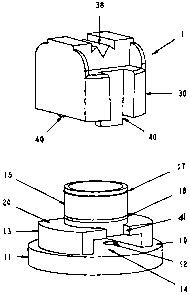
The inlet part 10 generally has a circular cross-
sectional shape having reduced stepped outer diameters as
shown particularly clearly in the side views Figures 1B,
1C and 1E. Figure 1C is a cross-section on lines I-I of
Figure 1A.
The base portion 11 of the inlet part 10 has the
greatest external diameter and has two apertures or
through holes 12 which define first inlets for a first
fluid. The through holes or first fluid inlets 12 pass
through the base portion 11 in a direction parallel to
the central longitudinal axis X-X of the inlet part 10.
The first fluid inlets 12 are symmetrically placed either
side of the central longitudinal axis X-X of the inlet
part 10 and so are positioned at an equal spacing on
opposite sides of the central longitudinal axis X-X. The
first fluid inlets 12 define flow paths A for the first
fluid in a direction parallel to the central longitudinal
axis X-X of the inlet part 10.
A second or intermediate portion 13 of reduced
external diameter is adjacent the base portion 10.
WO 99/17886 PCT/GB98/02974
-7-
Opposite sections of the wall defining the second or
intermediate portion 13 are relieved or absent so as to
provide opposed second inlets 14 for a second fluid to
enter through the second fluid inlets 14 into the hollow
centre 16 of the inlet part 10 in a direction B transverse
to the first fluid flow paths A. As can be seen from the
drawings, the second fluid inlets 14 open onto the first
fluid flow paths A and are thus crossed by flow of the
first fluid through the first fluid inlets 12. The second
fluid inlets 14 are at a position which is rotated through
90 around the longitudinal axis X-X relative to the first
fluid inlets 12. In the embodiment shown, the second fluid
inlets 14 are open to atmosphere.
The intermediate portion 13 of the inlet part 10 leads
onto a final portion 15 of reduced external diameter. This
final portion 15 defines therein a hollow cylindrical
volume 16 which will be discussed further below. The end
portion 15 of the inlet part 10 has a first external
annular bead 17 and a second external annular bead 18.
In this example, the intermediate portion 13 of the
inlet part 10 has four locating wedge-shape recesses 19
facing in a direction parallel to the longitudinal axis X-X
on the stepped surface 20 which connects the intermediate
portion 13 externally to the final portion 15.
Within the inlet part 10, at a position just
downstream of the second fluid inlets 14 and corresponding
to the junction between the intermediate portion 13 and
final portion 15 of the inlet part 10, is an intermediate
wall 21. This intermediate wall 21 has two circular
apertures 22 which are coaxial with and of slightly larger
diameter than the first fluid inlets 12.
The outlet part 30 of the spray nozzle 1 has a first
circular wall 31 which defines a mixing chamber 32 in the
CA 02307024 2000-04-05
WO 99/17886 PCT/GB98/02974
-8-
form of a cylindrical central volume 32. The circular wall
31 is sized to fit over the narrow portion 15 of the inlet
part 10 and has an internal annular recess 33. The outlet
part 30 has wedge-shape teeth 34 which correspond to and
are received in the wedge-shape recesses 19 of the inlet
part 10 to fix the relative orientation of the two parts
10,30 in the assembled spray nozzle 1.
As can be seen particularly clearly in Figures 2C,
which is a cross-sectional view on II-II of Figure 2A, and
in Figure 3B and 3E, which are cross-sectional views on
IV-IV and III-III of Figure 3A respectively, the central
volume 32 of the outlet part 30 terminates in a wall 35
which is opposite the first fluid inlets 12 in the
assembled spray nozzle 1. A through hole 36 which provides
an outlet from the central volume 32 is provided centrally
of the wall 35. The longitudinal extent of the outlet 36
is defined by a short cylindrical wall 37 running parallel
to the central longitudinal axis of the spray nozzle 1.
The short wall 37 has a wedge-shape recess 38 which flares
outwardly away from the outlet 36 to define a fan spray tip
as is well known in the art of spray nozzles. It will be
appreciated that the portion of the wall 37 surrounding the
outlet 36 can be provided with different shapes in order to
provide spray patterns of different shapes, such as cones
for example.
In use, the spray nozzle 1 is formed by assembling the
inlet and outlet parts 10,30 with the wall of the final
portion 15 of the inlet part 10 being received in the
central volume 32 of the outlet part 30. The second bead
18 snaps into the annular recess 33 and the first bead 17
provides a seal for the junction of the inlet and outlet
parts 10,30. The intermediate wall 21 of the inlet part 10
provides a pre-chamber 39 upstream of the mixing chamber
32. The assembled spray nozzle 1 can then be fitted to an
CA 02307024 2000-04-05
WO 99/17886 PCT/GB98/02974
-9-
agricultural boom by means of a conventional spray cap (not
shown) for example.
A first fluid, which may be a liquid such as a
solution of a pesticide or fertiliser for example, is
supplied under pressure to the first fluid inlets 12 so
that the first fluid flows in the direction indicated by
arrows A. The flow of the first fluid transversely past
the laterally disposed second fluid inlets 14 draws air in
through the second fluid inlets 14 into the pre-chamber 39
and the air is entrained with the first fluid. On passing
through the apertures 22 of the intermediate wall 21 into
the mixing chamber 32 provided by the volume 32 defined in
the outlet part 30, the first fluid strikes the opposed
wall 35 of the inlet part 30. It will be appreciated that
because the first fluid inlets 12 are offset relative to
the outlet 36, there is very little tendency for the first
fluid to pass straight out of the outlet 36. The
intermediate wall 21 tends to prevent the fluid in the
mixing chamber 32 passing back to and out of the second
fluid inlets 14.
After striking the wall 35 opposite the first fluid
inlets 12, the first fluid having entrained air atomises to
produce air-filled droplets on being forced out of the
mixing chamber 32 by the action of further incoming first
fluid entering the mixing chamber 32 through the first
fluid inlets 12 and apertures 22 of the intermediate wall
21. It will be appreciated that this is achieved without
requiring a long mixing chamber, in contrast to the prior
art spray nozzles of this type. The effective mixing
chamber of the present invention is provided by the
relatively short volume 32 of the second part 30.
A second example of a spray nozzle 1 in accordance
with the present invention is shown in Figures 5A and 5E.
The second example is similar to the first example
CA 02307024 2000-04-05
WO 99/17886 PCT/GB98/02974
-10-
described above and those parts which are the same have the
same reference numerals and will not be further described.
The second example of the spray nozzle 1 differs in
the way relative orientation of the two parts 10,30 is
achieved. In the second example of the spray nozzle 1, the
wedge-shape recesses 19 and wedge-shape teeth 34 of the
first example are replaced by a pair of opposed lugs 40 on
the second part 30 which project rearwards of the second
part to engage with corresponding opposed recesses 41
provided in the stepped surface 20 which connects the
intermediate portion 13 externally to the final portion 15
of the first part 10.
It has been found that the spray nozzle of the present
invention can operate at a pressure of only 3 bar
(approximately 300 kPa) which is much less than the 7 bar
(approximately 700 kPa) required of some prior art spray
nozzles of this type as discussed above. A pressure of 3
bar (approximately 300 kPa) is more typical of the
pressures used in conventional spraying equipment and
therefore the spray nozzle 1 of the present invention is
much more convenient for the user. The spray components
which incorporate the spray nozzle 1 are much less likely
to suffer damage, for example to seals, due to the supply
pressure of the first fluid.
It has also been found that the manufacturing
tolerances required of the spray nozzle 1 of the present
invention are much less stringent than those similar spray
nozzles of the prior art. For example, in the " TurboDrop"
spray nozzle mentioned above, it is necessary to balance
carefully the inlet orifice size compared to the outlet
orifice size to within very fine tolerances in order to
prevent flooding and liquid outflow through the air inlet.
In the present invention, the requirements on manufacturing
are much less stringent. The present invention allows the
CA 02307024 2000-04-05
. , == ==
, = .= ' = = ' R = = = =
. ' ~ t = ' = = = = =
. l = = . l t =110 = #=
. 1 ~ 1 = .. = = =
' n = i ~ = = = .l = = = ~ =
- ~ ~ -
outlet orifice size to be varied relatively freely, which
allows much greater freedom in manufacture which in turn
enables the ultimate droplet size to be varied simply by
providing different outlet parts 30 having different sizes
for the outlet 36. Different droplet sizes have different
dispersion characteristics and therefore the present
invention allows the user to obtain the required dispersion
characteristic more easily. In some circumstances, a small
droplet size is preferred whereas in other circumstances a
larger droplet size is preferred. At present, the reason
for the less stringent requirements on manufacturing
tolerances is not clear but it is believed to be related to
the non-alignment of the inlets and outlets in the spray
nozzle 1 of the present invention.
Moreover, the size of the apertures 22 of the
intermediate wall 21 can be adjusted to provide some degree
of control over the amount of air which is drawn in through
the second fluid inlets 14.
.K
The inlet and outlet parts 10,30 can be made of any
suitable materials, including plastics such as acetal.
An embodiment of the present invention has been
described with particular reference to the examples
illustrated. However, it will be appreciated that
variations and modifications may be made to the examples
described within the scope of the appended claims. For
example, more than two first fluid inlets may be provided,
there preferably being a corresponding number of apertures
in the intermediate wall. More than two second fluid
inlets may be provided.
CA 02307024 2000-04-05
AMENDED SHEET