Note : Les descriptions sont présentées dans la langue officielle dans laquelle elles ont été soumises.
CA 02307282 2005-O1-11
1
MICROPHONE UNIT
The present invention relates to a microphone unit for use with a portable two-
way
radio transceiver, for enabling oral communication via the radio transceiver,
said
microphone unit including a locating device for enabling said radio
transceiver to
transmit a signal containing position locating information.
In particular, but not exclusively, the invention relates to an alarm device
which, when
utilised in conjunction with a separate radio transceiver, provides that
transceiverwith
features which did not previously exist. These additional features enable the
location
of the user of that transceiver to be determined automatically or manually,
independently of or as a result of the activation of an alarm, either directly
or
indirectly. This location information may be reported to the user of the hand
held
radio, other system users or a central controller. The added device will
therefore
provide the transceiver with a number of very useful features which may not
have
been originally incorporated within the original product at a very economic
cost.
Prior art devices which exist are described by patent No. GB 2 051 4448
(Ericsson),
patent No. GB 2 223 8698 (Tunstall) and patent publication No. GB 2 223 380A
(Shorrock Ltd). Ericsson discloses a system including a receiver unit and a
transmitter unit, which when enabled transmits a location code and an
identification
code. The system also includes a number of strategically placed low power
transmitter devices which due to their location and low power are able to be
related
to a specific area within a building.
These location transmitters would typically be placed near each door within a
building, each would have a unique identity and a range of typically 5 metres.
When
the portable device is within range of the location transmitter it will
receive and store
the location information. In the event that the alarm transmitter is
activated, the
transmitter sends its own unique identification togetherwith the stored
identity of the
last received location transmitter.
CA 02307282 2000-04-14
2
A central receiver can then process this information and with a reasonable
degree
of certainty determine the location of the person who activated the alarm.
Tunstall suggests a number of improvements to the Ericsson art, such
improvements
include the ability of the portable transmitter device to receive and store
information
from a plurality of location transmitters together with additional coding to
enable a
more accurate location fix to be determined, particularly if the system is
required to
operate within a building having more than one floor. A further improvement
includes
the ability of the local transmitter to initiate the portable alarm
transmitter
automatically by means of a modified location identity code.
Shorrock discloses technology which is very similar to Ericsson, however in
this
instance the location identifying units are interrogated to initiate the
emission of the
location information. An alternative embodiment makes use of well known bar
code
reading technology to determine the location of the individual.
All of the described prior art comprises a self contained alarm transmitter
with
integral locating device receiver I interrogator which can send an alarm
signal
together with the location of an individual in distress. Additional product
exists within
the market (hereinafter also referred to as prior art) which utilises the same
technology, however the hand held alarm unit also includes a microphone and
speaker arrangement with a receiver so that the unit can also be used for two
way
speech.
Since such products effectively comprise a two way personal radio with the
locating
technology combined within the one unit they tend to be very expensive when
compared with standard two way radio transceivers.
A major disadvantage with the prior art is that any organisation wishing to
provide
their staff with an alarm system which utilises this type of location
reporting
technology must purchase this implementation of the technology even though
they
may already have an existing system utilising portable two way personal radio
equipment. The lack of compatibility between the two systems is clearly
undesirable.
AMENDED SiiEEf
CA 02307282 2000-04-14
' , " 1 ' ; . : ' - ,
. , , ' ~ , , ,
" . ~ , . . , . ,
3
Furthermore, the prior art alarm technology disclosed generally uses low power
radio
transmitters because the radio regulations stipulate certain frequencies must
be used
for such alarm equipment and the authorities only permit low power
transmitters to
be used on such frequencies. This results in a significant amount of system
infrastructure being required in the event that a large site such as a
shopping centre,
large industrial facility or a prison is in need of protection.
Patent No. GB 2 247 761 A (Davis) discloses an alarm interface which is
applied to
a modified PCN (personal communications network) handportable. Davis suggests
that the potential location of the handportable can be determined by virtue of
the cell
being used within a cellular radio network. This approach has two major
disadvantages. The first being that the handportable needs to be modified.
Modification can be expensive (if even possible), more importantly radio
transmission
equipment requires radio regulatory type approval testing, and such regulatory
approval is invalidated upon modification of the approved product unless it is
re-
submitted for type testing. This is a very expensive process for hand portable
radios
and cellular radio equipment in particular. This option is clearly impractical
for users
of existing systems.
A second disadvantage is that it is only possible to identify location within
the general
coverage area of a cell. In a city typical cell coverage might be two
kilometres in
diameter which results in a totally inadequate positional resolution to be of
any real
use in an emergency.
It is an object of the present invention to provide a locating system that
mitigates at
least some of the afore-mentioned disadvantages.
According to the present invention there is provided a microphone unit for use
with
a portable two-way radio transceiver, for enabling oral communication via the
radio
transceiver, said microphone unit including a locating device for enabling
said radio
transceiverto transmit a signal containing position locating information, said
locating
device comprising a sensor for sensing a signal containing position locating
information, a memory for storing position locating information obtained from
said
signal, a communications device for communicating with said radio transceiver,
a
At~c~C~~ ~t~i=ET
CA 02307282 2000-04-14
4
control device for controlling said radio transceiver via said communications
device
and an activating means for activating said locating device, the arrangement
being
such that when the locating device is activated, said control device causes
said radio
transceiver to transmit a locating signal containing the position locating
information
stored in said memory.
The invention provides a microphone unit that can be connected to a
conventional
handportable radio transceiver, which enables the transceiver to transmit a
locating
signal containing position locating information. The location of the
transceiver from
which the locating signal was sent can thus be easily determined, allowing
help to
be sent quickly. Because the locating device is connected to an existing
handportable radio, a separate radio transmitter is not required and the
system is
thus very economical and users of the system are not required to cant'
additional
items of equipment. Radio type approval is also not required and relatively
high
power radio transmitters can be used, thus minimising the necessary
infrastructure.
The microphone unit may be used as a replacement for a conventional
microphonelloudspeaker unit.
Advantageously, the arrangement is such that when the locating device is
activated,
the control device causes said radio transceiver to transmit an alarm signal.
The
alarm signal may be transmitted simultaneously with the signal containing
position
locating information or separately therefrom. For example, the alarm signal
may be
transmitted first and the signal containing position locating information may
be
transmitted later, when demanded by the receiver of the alarm signal.
The sensor may be adapted to receive a signal containing position locating
information from a local transmitter. The sensor may be adapted to receive an
infrared signal, an ultrasound signal, an inductive signal, an electrostatic
signal or an
electromagnetic signal, for example a HF, UHF or VHF radio signal.
Alternatively, the sensor may be adapted to receive a plurality of signals
from remote
transmitters and to derive position locating information from those signals.
For
example, the position locating information may be derived from GPS signals or
by
means of interferometry.
~,w~l'L~~~ '~'~'~~J
W 1
CA 02307282 2000-04-14
', ,
The activating means may comprise a switch provided on the locating device, a
remote switch having means for transmitting an activation signal to the
locating
device, means for sensing unauthorised removal of the locating device, means
for
sensing excessive movement, lack of movement andlortilting of the locating
device,
5 means for sensing an activating signal transmitted to the locating device
from a
remote transmitter, either directly or via the radio transceiver, or any
combination of
these.
The locating device may be arranged to cause the radio transceiver to transmit
audio
activity automatically in the event of said locating device being activated,
and may
include means for recording audio activity taking place prior to activation.
The locating device may include means for storing an identification signal
identifying
said locating device, the arrangement being such that when the locating device
is
activated, the communications device causes the radio transceiver to transmit
a
locating signal containing said identification signal.
According to a further aspect of the present invention there is provided a
locating
system including a microphone unit as described above and a plurality of
transmitters, each transmitter being arranged to transmit a signal containing
position
locating information. The system may also include a central station for
receiving
locating signals andlor alarm signals. Alternatively or in addition, each
locating
device may be arranged to receive locating andlor alarm signals transmitted by
other
locating devices.
A preferred embodiment of the invention provides a device which can, when
connected to the existing two way personal radio, provide that two way radio
with,
as a minimum, all of the features of the prior art. Furthermore, because the
existing
transmitter and receiver within the two way radio are used, the technology
required
and hence the cost of the features is significantly reduced. Because there is
no need
to modify the existing equipment the issue of invalidating product type
approval is
avoided.
~e:'~ r;= _.
_..
CA 02307282 2000-04-14
6
A further advantage is that the power of the transmitters used in two way
personal
radio equipment is generally much higher, since the regulations permit this.
Large
sites such as shopping areas are therefore easily protected at very reasonable
cost.
Other methods of identifying the location of an individual which rely upon
some form
of processing within the device held by the individual include the well known
Global
Positioning System (GPS), and more recently interferometry techniques have
been
introduced. One technique, known as Cursor, is disclosed by Duffett-Smith and
Woan and has a variant called High Precision (HP) Cursor. These and any future
location technologies are readily incorporated with this new invention.
The present invention therefore provides a significant improvement in the
scope of
application of the existing prior art and other methods of location
identification.
Many individuals who are responsible for the security of a building or similar
facility,
or who work alone, carry two way personal radios to enable them to contact
their
I v:'.~-~ S'_~~....,
CA 02307282 2000-04-14
WO 99/21149 PCT/GB98/b2830
7
control centre or another party in the event that they require assistance or
need to
simply provide periodical communication to confirm their location and good
health.
A disadvantage with this technique is that the location reporting is very much
dependent upon the skill of the individual to know where they are. The
technique
also relies upon the individual being able to report this information,
something they
may not be able to do in the event they are incapacitated or being threatened
by
another individual.
The prior art technology can be (and in some cases has been) incorporated
within
the two way personal radio but this almost always results in some kind of
performance compromise. In addition, because this means of implementation is
complicated and relatively difficult to produce such systems are generally
very
expensive when compared with standard two way personal radios.
A further problem is that such location based two way radios are generally not
compatible with any existing two way radio system infrastructure which may be
in
place. In addition, in the event that a more effective location technology is
developed, it is not easy to upgrade the system as required: the entire system
has
to be replaced.
The present invention provides a very cost effective solution for these
problems
which also enables existing radio system to be upgraded very simply and cost
effectively. The concept of the invention can easily be applied to other
communication devices such as cellular radios and mobile radios installed
within
vehicles.
Virtually all types of personal radio available include a facility to connect
an optional
remote lapel microphone I loudspeaker unit isometimes referred to as an
accessory
connector). Such lapel microphone/loudspeaker units also include a switch to
activate the transmitter when the user wishes to speak.
This external lapel microphone / loudspeaker unit enables the user to keep
their
portable radio on their hip, waist or covertly hidden. A further benefit is
that such
CA 02307282 2000-04-14
WO 99/21149 PCT/GB98/02830
8
an option provides protection for the user's head from the electromagnetic
signal
generated by the radio transmitter aerial, a subject of some concern in recent
times.
The connection style and format for these lapel microphone / loudspeaker units
is
usually specific to the manufacturer, but common for each version of radio.
The
connections provided are usually as a minimum:
signal wires for the lapel loudspeaker,
signal wires for the lapel microphone, and
signal wires for the press to talk or transmit switch
An embodiment of the present invention provides a special version of the
optional
lapel microphone / loudspeaker unit (hereinafter referred to as the "lapel
unit"),
which includes circuitry that has the ability to determine the location of the
lapel
unit and enable the user to send voluntary or involuntary alarms.
In the event that the version of personal radio for which the lapel unit was
designed
did not provide any electrical power at the lapel unit connecting point then
an
integral power supply (such as a batteryf would also be included.
Inclusion of a microcontroller and modem technology, the principle of which is
well
known, would enable the central control system to communicate with the lapel
unit
(or vice versa) either automatically or as a result of manual intervention on
the part
of the person using the lapel unit.
The exact nature of the location technology incorporated within the lapel unit
would
depend upon the needs of the customer. Typical situations in which the
invention
may be used include:
An individual who works within a building and has to patrol the various
locations within that building on a regular basis.
An individual who has to patrol an area outside a building or a mixture of
outside and within a building or buildings
CA 02307282 2000-04-14
WO 99/21149 PCTIGB98/02830
9
An individual who has to work alone in wide area open spaces, such as a
farmer.
An individual who has to work in a situation represented by any combination
of the above.
Different technology works better in different situations. Ericsson, Tunstall
and
Shorrock describe technology which works very well within buildings. The
preferred
method described utilises electromagnetic I inductive coupling at typically
150KHz.
This is because this technology has the ability to penetrate clothes which may
cover the alarm transmitter worn by the person being protected.
A disadvantage with this method, which is described by the Tunstall document,
is
that the signal is capable of penetrating walls, floors and ceilings. The use
of
infrared is not recommend because it is relatively poor at penetrating
clothing.
An advantage with the lapel unit is that such units are worn externally in
order for
the user to be able to hear any message which may be sent via the speaker
unit.
Since the lapel unit is not covered, infrared can therefore be used as one
method
of internal location identification with a high degree of success. Localised
infrared
transmitting beacons can then be deployed to identify the required areas.
Ultrasound based location beacons could also be used for the same reasons.
The use of inductive coupling for outside applications is not very effective,
principally because the range of these location transmitters is generally very
limited
at typically five metres. A much better alternative would be to use higher
frequency
VHF or UHF low power transmitters, the preferred operating frequency being in
the
170MHz to 900MHz range. These devices have a range of typically 50 to 100
metres and can be easily adjusted to provide a range to suit the location
concerned.
A compatible receiver would be fitted within the lapel unit.
The low power UHF I VHF location beacons can easily be installed in external
locations such as the periphery of a building, the propagation of the signal
being
controlled in such a manner that the signal does not penetrate the building
and
CA 02307282 2000-04-14
WO 99/21149 PCT/GB98I02830
la
confuse the system. An advantage with the low power VHF / UHF location beacons
is that they are very efficient and do not require much power. This would
enable the
location transmitter to be powered by battery for a significant period of
time,
typically one year or more.
The location beacon could also incorporate a low battery alarm which could be
relayed to the control system to advise when the battery requires replacing.
This
again results in very cost effective installation because wiring to provide
power to
the location transmitter is not required. In instances where the ambient light
was
known to be dependable solar power could be used to eliminate the need to
change
batteries.
For larger areas such as open fields the lapel unit could incorporate a GPS
receiver.
At the present time GPS receivers require a relatively high amount of power,
as
technology advances however this will not continue to be a significant issue
and
the incorporation of GPS technology with a lapel unit would be practical and
cost
effective.
Until such time as the GPS unit is sufficiently small enough and power
requirements
are sufficiently low enough for such integration the GPS unit could be carried
in a
separate unit which can by means of using the location receive data path
transmit
the GPS location data to the lapel unit for re-transmission by the personal
radio.
This would be particularly useful in a vehicle where the GPS module would be
separate and the location data passed to the lapel unit whilst this was at
rest on the
dashboard. In such instances location data transfer could be either by low
power
radio or infrared, for example.
An alternative would be to incorporate a receiver within the lapel unit to
receive the
signals from the HP Cursor technology, an alternative to GPS. The resulting
data
could then be transferred to a central computer to enable the position of the
individual to be determined. At present the HP Cursor technology provides
reliable
positional accuracy of typically 1 metre.
As the HP Cursor technology improves it will no doubt be possible to achieve
CA 02307282 2000-04-14
WO 99/21149 PCT/GB98/02830
11
greater positional resolution thereby avoiding the need to use internal
location
beacons. The system software would however need to determine the general route
of an individual in order to identify which side of a wall a person may be,
for
example. Alternatively, a small number of fixed beacons could be used to
assist in
the identification of floors, these beacons also assisting in the dynamic
calibration
of HP Cursor since their fixed location would be a constant.
As and when alternative location determining technology which requires some
form
of sensor at the portable equipment in order for the location to be determined
is
developed, the appropriate processing circuitry could be incorporated within
the
lapel unit to enable existing personal radio equipment to benefit from such
advances
in technology without modification.
In a similar manner, the lapel unit can incorporate any combination of the
described
location technology in order to provide the most effective solution.
The capability of the invention to receive and process large area based
location
technology also permits a further application of the invention for the purpose
of
determining the location of vehicles. Vehicles which utilise two way radio
systems
can also suffer from the previously described problems associated with
providing
such radio equipment with location based technology.
In this instance a separate GPS based location determining module could
transfer
the location data to the microphone unit for transmission to a central
computer by
means of the two way radio within the vehicle. Because of the very short range
within the vehicle, infrared would be the preferred method to transfer
location data
from the GPS receiver to the microphone unit.
Once again it can be seen the invention permits very cost effective upgrade of
existing radio installations to enable valuable additional facilities to be
provided with
ease.
Once the required location technology has been implemented, it is very easy to
include additional features such as a panic button which the user can press
when
CA 02307282 2000-04-14
WO 99/21149 PCT/GB98/02830
12
assistance is required in the event of an emergency. Further features would
include
a facility to detect the forced removal of tfie lapel unit from the wearer,
and a
mechanism to detect that the wearer has stopped moving, has fallen over, or is
running. The system could also include a facility to check the correct
functioning
of the entire system on a periodical basis.
A particular problem which exists for sensitive situations such as prison
officers is
that the very act of being seen to activate the panic switch can provoke
attack. If
the version of lapel unit with a VHF I UHF receiver is used (as when detecting
VHF
I UHF location beacons) then the user could be provided with a miniature panic
transmitter which could be disguised as a key fob and kept in the pocket or as
a
piece of jewellery such as a ring worn on the finger.
The covert activation of such a low power transmitter would be detected by the
lapel unit as a special alarm code and would therefore command the portable
transmitter to send the appropriate alarm signal to the control room.
Another useful feature in sensitive situations would be the ability to record
the
audio sounds which took place in the time prior to the alarm being raised.
Such
microchip recording technology is well known, and could be incorporated within
the
lapel unit with the ability for the central controller to control the replay
of the
recorded audio. The sensitivity of the microphone could be controlled to
enable any
audio within the general area of the lapel unit to be transmitted back to the
control
room.
Once the alarm and location information has been received at the central
equipment
it can then be processed as required. This processing may be by action of a
human
operator, or automatically by means of a computer system which having
processed
the alarm and location information could arrange for the appropriate pre
recorded
alarm and location messages to be broadcasted to other individuals capable of
rendering assistance. Should these other individuals also have the lapel unit
with
location technology the system could advise which individuals were most
appropriately located to render assistance soonest.
CA 02307282 2000-04-14
WO 99/21149 PCT/GB98/02830
13
These and other objects of the present invention will become readily apparent
upon
further review of the following specification and drawings.
An embodiment of the present invention will now be described, by way of
example,
with reference to the accompanying drawings, in which:
Figure 1 is a sketch of a hand held personal radio with the lapel unit,
Figure 2 is a sketch of a personal radio with the lapel unit in conjunction
with
location devices and the central control system,
Figure 3 is a block diagram of the system based upon HP Cursor,
Figure 4 is a block diagram of a location transmitter, and
Figure 5 is a block diagram of the lapel unit.
A preferred embodiment of the present invention is detailed in figure 1 where
lapel
unit 101 is connected by means of an accessory connector 103 to a conventional
handportable radio unit 102. The lapel unit 101 comprises an infrared
detection
window 104 to determine location by reception of signals from location
transmitters, a microphone / speaker unit 105, a transmit button 107, a panic
button 106 for use when in distress and a clip 109 which is attached to the
user
such that when the lapel unit is removed alarm pin 108 is pulled activating a
snatch
alarm.
For covert activation of the panic alarm a small discrete hand held
transmitter 110
can be operated without the user having to touch the lapel unit or the hand
portable
radio. Hand held transmitter 1 10 could be adapted and incorporated within
other
items resulting in an alarm being detected when the wearer of the system
entered
an area within which the transmitter was located.
When the location of the user needs to be determined over a large area, GPS or
interferometry techniques would be used. In this instance wide area location
CA 02307282 2005-O1-11
14
determining sensor 111 could either be incorporated as an integral element of
the
lapel unit or provided as a separate belt worn unit. In this instance the
location data
would be transferred to the lapel unit by means of a modified location beacon
transmission.
Figure 2 demonstrates a typical use of the invention where a number of
preferably
infrared, but optionally ultrasonic, inductive or electrostatic based location
devices
201 - 205 would be placed within the building whilst a number of preferably
VHF /
UHF but optionally inductive, ultrasonic or electrostatic based devices 206 -
209
would be placed externally to the building. The combined handportable
transceiver
I lapel unit 210 would then detect each location beacon 201-209 as the wearer
passed each beacon and so enable the location to be determined. When
commanded to do so either automatically or by action of the wearer the
combined
handportable transceiver / lapel unit 210 would communicate its location to
central
control unit 211. The general concept of such a system for location
identification is
detailed by Ericsson in GB 2 051 4448.
Figure 3 describes an system utilising the HP Cursor technology. The location
technology is relatively new and is therefore described herein to provide an
appreciation of its application within this new invention.
A minimum of three fixed transmitters 301, 302 and 303 are required. Indeed
these
transmitters can be existing public broadcast transmitters if desired, however
there
are disadvantages to this as described by Duffett-Smith and Woan. The
preferred
operating frequency of these transmitters is in the region of 2 MHz, each
transmitter
having a different frequency with in a band of typically 10 KHz.
A fixed receiver 304 is used to enable comparisons in the characteristics of
the
received signals from 301,302 and 303 with that of the received signal from
lapel unit
305. The preferred characteristic to be measured with HP Cursor is the phase
difference of each signal. A system processor 306 is used to analyse the
signals
received from fixed receiver 304 and mobile receiver 305 in order to determine
the
location of mobile receiver lapel unit combination 305. Note that processor
306
CA 02307282 2000-04-14
WO 99121149 PCT/GB98/02830
could in fact be located within the lapel unit 305, at the fixed receiver 304
or any
intermediate location. A preferred option would be with fixed receiver 304.
This
would reduce the cost of lapel unit 305 and that of the entire system since
processor 306 could clearly calculate data for a plurality of lapel units.
5
The location transmitter described in figure 4 comprises an encoding device
401
which generates data to enable the specific location of the location
transmitter to
be identified, driver unit 402 which would convert the code signal into one
suitable
to drive either infrared output 403, induction output 404, electrostatic
output 405,
10 HFNHF/UHF output 406 or ultrasound output 407 as desired depending upon the
preferred location transmitter technology.
Power unit 408 provides all location transmitter modules with operating
voltage and
can be powered by battery, solar energy, mains or any combination of the
three.
15 Power unit 408 can also incorporate a monitor to modify the transmission
code of
encoding device 401 so that the central monitor can be advised of the power
status
of the location transmitter. In a similar manner a sensor could be
incorporated to
indicate unauthorised tampering with the location transmitter.
In the event that the location transmitter is to used as a source for phase
measurement as an element of the HP Cursor system the encoding device 401
would not be necessary, since this technology only requires a carrier signal
from the
fixed transmitters. Occasional identification coding could however be used as
a
means of monitoring the correct function of the transmitter.
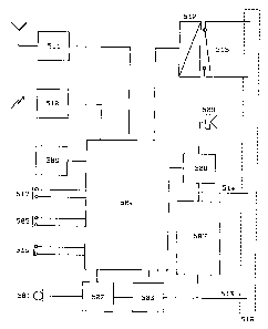
The lapel unit is described in greater detail in figure 5 and comprises a
number of
elements. The circuitry within the lapel unit needs to be interfaced with the
handportable radio for receive audio I data, transmit audio I data and
transmitter
control. The data is interfaced by means of modem 507, receive audio wires 514
and transmit audio wires 513, and transmit / receive control is achieved by
transmit
enable relay 512 and transmit wires 515. A connector 518 which would be of a
type suitable to interface with the desired transceiver would be fitted to the
end of
the lapel unit wires to facilitate connection to the transceiver.
CA 02307282 2000-04-14
WO 99/21149 PCT/GB98/02830
16
Under normal circumstances the handportable will be in receive mode and the
contacts of transmit relay 512 open. Any received information will be sent via
the
lapel unit connector 518 to receive path wires 514 to modem 507 and speaker
amplifier 508. Data received by modem 507 is processed by microcontroller 504.
If the data message indicates that speech is available for the lapel unit then
microcontroller 504 will turn on speaker amplifier 508 and route the receive
audio
to speaker 509. If an audio bleep alarm is required to alert the user the
microcontroller 504 can produce this and activate the speaker 509 using
amplifier
508.
Should the user wish to speak to the control centre then closing push to talk
switch
505 will instruct the microcontroller 504 to close the contacts of push to
talk relay
512 sending a transmit signal to the lapel unit connector via transmit
function wires
515. If desired, the lapel unit could automatically send lapel unit
identification and
location data by means of modem 507 and transmit audio wires 513 each time the
press to talk button 505 is activated. When the user speaks speech is detected
by
microphone 501 and amplified by microphone amplifier 502 before connection to
the handportable by transmit audio signal 513.
Speech recording chip 503 is activated if required to record audio detected by
microphone 501 on a continuous basis. In this instance microphone sensitivity
is
controlled by microcontroller 504 so that any important sounds (such as in a
struggle prior to an attack) are recorded. Upon receipt of the appropriate
command
from the central controller the microcontroller 504 will play back any
recorded
sounds and transmit these via the connected handportable to the controller for
analysis.
Infrared receiver 510 is for internal building use and sends demodulated
infrared
data to microcontroller 504 for analysis and storage. Depending upon exact
programme instructions held within microcontroller 504 the location data can
either
be stored yr transmitted immediately (and automatically) by activation of
transmit
relay 512 and use of modem 507. A significant benefit of a two way system is
that
the microcontroller 504 can communicate with the control system to determine
that
a good radio path exists prior to sending the location and identification
data.
CA 02307282 2000-04-14
WO 99/21149 PCT/GB9$/02830
17
Furthermore, once this data has been sent the central control system can
confirm
that the data was received without any errors. In situations where the use of
infrared is undesirable, inductive or electrostatic techniques can be used for
in-
building location transmitters providing due regard is given to problems
relating to
penetration of walls, floors and ceilings as has been mentioned before.
UHF I VHF receiver 511 is for reception of signals from low power UHF I VHF
location transmitters which may be placed in outside areas. Alternatively, the
receiver 511 can be used to receive and process data from a co-located GPS
receiver module, or indeed may be replaced by a GPS receiver module. Received
data is again processed by microcontroller 504 as previously described for the
infrared receiver 510. Receiver 51 1 can also be used to receive special alarm
codes
from local beacons or a covert attack transmitter held by the lapel unit
wearer or
perhaps an associated party.
Sensor 506 detects either lack of movement, too much movement (running) or a
horizontal position (individual collapsed), depending upon the nature of the
sensor.
The sensor activity is processed by microcontroller 504 which would typically
warn
the user by means of a bleep via amplifier 508 and speaker 509 before
transmitting
an alarm and location information. This would enable the wearer of the lapel
unit
to cancel what might be a false alarm due to a temporary change in posture in
the
event of a tilt sensor being used, for example. In the event that suitable
power was
not available from the handportable radio via connector 518 then a local
battery
power supply would be provided with low battery alarm function to warn the
user
accordingly.
Normally closed switch 516 is used to detect unauthorised removal of the lapel
unit
from the wearer and send an appropriate emergency alarm to the central
control.
In a similar way attack switch 5 9 7 would send an attack alarm signal to the
central
control room if activated by the lapel unit wearer. In all cases location
information,
identification information, and live and recorded audio could also be
transmitted.
There may be some instances where the user would not wish to wear a lapel unit
but carry the handportable radio or wear the handportable radio at waist level
by
CA 02307282 2000-04-14
WO 99/21149 PCT/GB9$102830
1$
means of a clip or belt. In this instance the "lapel unit" would be fashioned
in such
a manner that it could be physically placed alongside the handportable radio
whilst
still being connected by means of the external microphone / loudspeaker or
accessory connector.
Clearly any of the preferred location determining technologies could be
replaced by
or complemented with alternative technology such as Global Positioning System
or
interferometry (HP Cursor) based location technology, or any future technique
for
location determination which may be developed. In a similar manner the lapel
unit
could readily incorporate more than one type of positioning technology to
satisfy
the overall requirement for location identification, e.g. infrared for within
a building,
and HP Cursor far outside the building.
According to a preferred embodiment of the invention there is provided a
device
'! 5 comprising a means of transferring audio signals to or from an
independent radio
configured with a transmitter and a receiver with a means of determining the
location of the device such that the location of the independent radio can be
determined, the location information being provided as a result of
electromagnetically coupled positioning signals, the analysis of which enable
the
position of the device to be determined.
The electromagnetically coupled location information may be provided by means
of
individual location beacons providing a signal which uniquely identifies the
location
concerned, or individual Earth based transmitters, the subsequent analysis of
which
enables the location to be determined, or individual orbital satellites, the
subsequent
analysis of which enables the location to be determined.
Advantageously, an alarm can be initiated as a result of action by the user of
the
device, or as a result of lack of action by the user of the device.
Advantageously, transmission can be initiated as a result of the receipt of
the
electromagnetically coupled location information or data contained within the
electromagnetically coupled location information, or as a result of failure to
receive
the electromagnetically coupled location information.
CA 02307282 2000-04-14
WO 99121149 PCT/GB98/02830
19
Advantageously, an alarm can be initiated as a result of action by a person
other
than the user of the device, or the receipt of an electromagnetically coupled
signal
initiated by another alarm transmitter.
The transmitters may be powered by self contained power sources, optionally
with
the assistance of solar energy.
Advantageously, the audio activity taking place prior to activation can be
recorded.
Advantageously, the device is worn on the body separately to the transceiver
and
is connected to the transceiver by means of electromagnetic connection.
Alternatively, the device is co-located with the associated transceiver and is
connected to the transceiver by means of an electromagnetic connection.
The invention also preferably provides a system comprising at least one
location
transmitter and a location determining device that can be connected to an
existing
radio transceiver in such a manner that the regulatory type approval of that
radio
transceiver is not impaired, the device being capable of maintaining the
speech
communication with the radio transceiver whilst also providing the capability
to
send an alarm and determine the location of the radio transceiver by receiving
and
decoding a signal from the location transmitter and reporting the alarm and
location
information to a central controller. Alarm conditions can be provided with
location
information either by means of action of the user, lack of action of the user
or by
automatic initiation of the system. The device can also incorporate other
location
based technology such as the Global Position System or interferometry for
large
area location determination. The device can also receive modified
transmissions to
initiate covert alarm conditions.